Robust quantum gates and a bus architecture for quantum computing with rare-earth-ion doped crystals.
Abstract
We present a composite pulse controlled phase gate which together with a bus architecture improves the feasibility of a recent quantum computing proposal based on rare-earth-ion doped crystals. Our proposed gate operation is tolerant to variations between ions of coupling strengths, pulse lengths, and frequency shifts, and it achieves worst case fidelities above with relative variations in coupling strength as high as and frequency shifts up to several percent of the resonant Rabi frequency of the laser used to implement the gate. We outline an experiment to demonstrate the creation and detection of maximally entangled states in the system.
pacs:
03.67.-a, 33.25.+k, 82.56.JnIntroduction
The Rare Earth Quantum Computer (REQC) recently proposed by Kröll and coworkers is a solid state ensemble quantum computer based on laser-addressed rare earth ions embedded in cryogenically cooled inorganic crystals Ohlsson et al. (2002); Nilsson et al. (2002). Internally, the system consists of a macroscopic number of independent instances of the same quantum computer. The qubits, represented by ground state hyperfine levels in the rare earth ions, are divided into channels according to the inhomogeneous frequency shifts of an optical transition in the ions. Every instance of the quantum computer has one representative from each active channel, and the instances are operated in parallel by addressing the channels with resonant optical radiation.
The inhomogeneous shift of the ions in a given channel will not be quite identical, and there will in general be fluctuations in their coupling to an applied coherent field. Also, the static dipole coupling used to mediate multi qubit gate operations will differ between instances. As a consequence, we must use gate operations that are stable with respect to variations in these parameters which, as we will demonstrate in this paper, may be achieved by using composite pulses and phase compensating operations.
One of the exciting features of REQC is that the size and coupling topology of the quantum computer is not defined by the crystal, but rather chosen in an initialization stage at each start-up of the system. The choice of architecture determines the number of instances available in a given crystal, and thus ultimately the scaling properties of the system. We propose to choose a bus-based architecture, as this will both allow for a higher number of instances and simplify the gate implementation as compared to the originally proposed architecture.
We conclude the paper with a proposal for an experimental demonstration of creation and detection of maximally entangled states in REQC systems.
I Quantum computing with rare earth ions
Rare earth ions embedded in cryogenic crystals have a number of features making them suitable for quantum information processing Longdell and Sellars (2002):
-
•
Ground state hyperfine levels with a lifetime of hours and decoherence times up to several . We will use three such states, labeled , , and , to implement quantum registers and for parking unwanted ions.
-
•
Optical transitions with homogeneous line widths on the order of are inhomogeneously broadened to several , allowing us to address a large number of independent channels.
-
•
The crystal-embedded ions have large static dipole moments with interaction energies up to several . This interaction is ideal for implementing gate operations of the dipole blockade type.
In the remainder of this section we will briefly introduce the basic ideas of REQC, as originally described in Ref. Ohlsson et al. (2002).
I.1 Dynamical architecture selection
The architecture of the REQC system is selected at start-up by an initialization procedure. The desired end-point of this process is a large number of independent instances of the chosen quantum computer, each instance being a group of ions with one representative from each active channel and couplings between the ions as required by the chosen architecture.
The initialization proceeds in two steps: channel preparation and identification of quantum computer instances. In both of these steps unwanted ions are deactivated by transferring them to off-resonant, metastable states.
Channel preparation.
A channel refers to a large number of ions distributed throughout the crystal, all having the same inhomogeneous shift and coupling strength within the inhomogeneously broadened optical transition used to access the ions. The channel preparation aims to deactivate all dopant ions close to resonance with a given channel and to transfer all members of the channel itself to their state.
This can be achieved by means of spectral hole burning techniques, and widths of the final channel structure as low as have been obtained experimentally for materials similar to those considered for use in REQC Longdell and Sellars (2002).
Instance identification.
After a successful initialization, each ion will only be interacting with ions from other channels, allowing us to ignore “excitation hopping” transitions Lukin and Hemmer (2000), as these will not be energy conserving. As a consequence we can model the dipole coupling as simple couplings between the excited states:
| (1) |
where the sum is over all pairs of ions. To be precise about the objectives of the instance identification process, we will consider ions and to be coupled if exceeds a threshold determined by the chosen implementation of the gate operation.
The goal of the instance identification procedure is to transfer ions, which are in an active channel but not members of a valid instance, to their auxiliary state . One way to achieve this is to go through the following procedure for each pair, , of channels required to be coupled:
By applying a -pulse to ions in channel we transfer the population to the state, thus shifting the excited state energy of all ions coupled to a channel ion. By means of a frequency sweep or a comb of rotations, all channel ions which are shifted less than are now transfered to their excited state , after which the channel ions are returned to . We now wait for the excited channel ions to decay, which will transfer part of the ions to the inactive state.
By repeated application of this pulse sequence, we can deactivate an arbitrarily high fraction of the channel ions which are not coupled to a channel ion. After this has been achieved, we repeat the process with the roles of channel and interchanged, and afterwards proceed to apply the same procedure to all other edges of the coupling graph to finally arrive at the desired initialized REQC system.
I.2 Gate operation
In general, the coupling strengths, , will differ between instances, requiring us to use gate operations that do not depend on the precise magnitude of the coupling strength.
One gate operation with this quality is the controlled phase shift based on the dipole blockade effect Jaksch et al. (2000). Assuming all ions not participating in the operation to be in their qubit states, and , and thus decoupled from the operation, we can implement a controlled phase shift in its simplest form by the following pulse sequence:
| (2) |
with representing the effect of a resonant pulse of area and phase applied on the transition of ions in channel .
For two coupled ions and , residing in channels and respectively, the effect of performing the pulse sequence (2) would be the following: If ion is initially in the state, the pulse transfers the ion to the excited state and thus shifts the pulse out of resonance, causing the system to return to the initial state after the last pulse. If, on the other hand, ion is initially in the state, it is not transferred to and the pulse is resonant and causes a phase shift on the state. The effect of the full gate operation on the qubit space is consequently a phase shift on the state: .
II High fidelity gate operations
Gate operations for the REQC system face a number of challenges due to the fact that they operate simultaneously on a number of not quite identical instances of a quantum computer: Due to the finite channel width, ion will in general be detuned by a small amount from the central channel frequency. Furthermore, the experienced Rabi frequency, , will differ slightly from the average Rabi frequency due to laser field inhomogeneities and local variations in dipole moments.
In this section we will show that by taking advantage of the fact that and are constant in time for each ion, we can design pulse sequences that perform almost the same operation on each instance.
II.1 Composite rotations
The pulse is driven by a Hamiltonian with signifying the Pauli-matrices in the basis and , where is a unit vector in the plane with azimuthal angle .
To apply the pulse we engage the field for a period , so that an ideal reference ion, , with and will be rotated by an angle around as desired. In general, however, the ions will react differently to the pulse due to their different detunings and coupling strengths.
The problem of taking all the ions through the same evolution when they react differently to the pulses has been studied in great detail in the magnetic resonance community Levitt (1986). Inspired by the discussion in Ref. Cummins et al. (2002) we have used the BB1 pulse sequence to replace a single pulse with the following sequence of pulses:
| (3) |
For our reference ion, , the unitary evolution caused by the composite pulse is seen to be exactly identical to the evolution caused by . The use of five pulses for this simple task is justified, however, if we instead consider the evolution of a general ion subject to the Hamiltonian
| (4) |
In this case we find that with the optimal value, , is almost constant over a large range of values of and , while changes quite rapidly.
II.2 Robust gate operation
For the two-level Rabi problem there is a global phase factor depending on the detuning which plays no observable role. In our three-level system, however, this phase will lead to a dephasing between the qubit level coupled to and the other qubit level. To compensate this, we must symmetrize the desired pulse sequence in a suitable way, to allow both levels to pick up the same, unknown, phase contributions.
In the case of the controlled phase shift (2), we have arrived at the following symmetrized version:
| (5) |
For the reference ion the pulse sequence is seen to be equivalent to , which is exactly the basic controlled phase shift operation (2), but we expect it to perform better for a general ion.
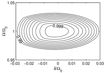
Implementing all the pulses of by composite BB1 pulses (3), we do indeed obtain a very robust implementation of the controlled phase shift as illustrated in Fig. 1. To asses the gate performance we have compared the effect of the gate to the desired gate operation, , in terms of the worst case fidelity, defined as the minimal overlap between the actual outcome of the pulse sequence and the desired outcome of the gate operation:
| (6) |
Since we know that the starting point of the gate operation will be a superposition of the ground hyperfine states, we have not minimized the expression (6) over the full Hilbert space, but rather restricted to the qubit space. Note that this modification ensures that any population in the excited state after the gate operation is counted as a loss of fidelity as it should be. The computation of the fidelity is discussed in more detail in the appendix.
As we see from Fig. 1 the pulse sequence obtains high fidelities over a much larger parameter space than the simple gate operation described by Eq. (2). This is highly desirable, as the minimal fidelity among the included instances determine the scale-up needed to perform error correction Steane (2002). Not too surprisingly, the sensitivity to variations in is improved the most, as this is the type of error best dealt with by the BB1 pulse sequence. For realistic parameters of the REQC system, a reduced sensitivity to variation would be more useful; whether this can be achieved by means of composite pulses is a point of further study.
| (a) | (b) |
|---|---|
 |
 |
III The bus architecture
As the architecture of an REQC system can be chosen at will, the question remains of which architecture to choose.
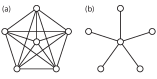
The fully interconnected “cluster” architecture suggested in the original REQC proposal of course has the minimal topological distance between qubits. On the other hand, a star topology with one central qubit coupled to the remaining qubits, as illustrated in Fig. 2, would reduce the number of required couplings from to , thus increasing the number of available instances in a given crystal, while still maintaining a topological distance of only .
Since the outer qubits in the star topology are not directly coupled, two-qubit gates between those must be mediated by the central qubit acting as a bus. To be specific, a bus-mediated controlled not gate can be constructed as
| (7) |
with the vertical lines signifying controlled phase shifts.
In addition to the better scaling properties of the bus architecture, its main advantage is that the bus qubit is a participant of all multi-qubit gates. This fact can be used to ease or improve the implementation of such gates: As an example, four times as many pulses are needed on channel as on channel with the proposed implementation of the controlled phase shift (5). If channel is chosen as the bus channel, a dedicated laser system can speed up the application of these pulses as compared to a tunable laser system able to address any channel.
IV Preparation and detection of maximally entangled states
To demonstrate the viability of the REQC concept, and in particular the bus architecture, we propose to perform an experimental preparation and detection of a maximally entangled state.
We will use an REQC system with star topology: one central qubit coupled to outer qubits. Starting with all qubits in their state, we apply a composite pulse Hadamard operation to the central qubit followed by controlled not operations on all the outer qubits controlled by the central qubit, thus transferring the system to the maximally entangled state
| (8) |
which corresponds to a superposition of the total pseudospin pointing straight up and straight down.
The following algorithm for detecting a population of the cat state is very similar to the method used by the group of D. Wineland to detect a maximally entangled state of four ions in a linear Paul trap Sackett et al. (2000): By rotating the state through an angle around the -axis we accumulate different phases on the pseudospin components: . An additional rotation by around the -axis now yields a state with an expected parity, , given by
the detection of the dependency thus signifying that the maximally entangled state has been populated Bollinger et al. (1996).
In a single-instance quantum computing system, such as the ion trap setup used in Ref. Sackett et al. (2000), we could measure the expectation value of the parity as a statistical average over many repetitions of the procedure described above: after each run we could simply measure the state of each qubit, and subsequently compute the parity. Since measurements in the REQC system yields an ensemble average, this approach would not be applicable here: we cannot find the expectation value of the parity from the ensemble averages of the single qubit parities, , which are as inspection shows.
Instead we let the bus qubit acquire the parity unitarily: by sequentially applying controlled not operations from each outer qubit to the central qubit we make the central qubit end up in the state in the case of odd parity and in the state in the case of even parity. After this, the ensemble average of the bus qubit population yields the expectation value of the parity.
As this section illustrates, readout from an ensemble quantum computer is conceptually somewhat more complicated than readout from a single quantum computer. It is worth noting, however, that unlike many other ensemble quantum computing proposals, REQC instances all start in the same pure state: if we successfully employ error correction during a computation all instances will end up in the same pure state, allowing us to read out the ensemble averages with high signal to noise ratio. Perhaps surprisingly, the readout can almost always be performed by tricks similar to those employed to detect the maximally entangled state: Ensemble quantum computing is almost as powerful as general quantum computing. In particular, all problems which may be expressed in terms of the hidden subgroup problem (such as Shor’s factoring algorithm) can be solved using an ensemble quantum computer Nielsen and Chuang (2000).
V Conclusions and Outlook
In conclusion, we have shown that, in the absence of decay and decoherence, it is possible to implement robust high-fidelity gates for the REQC system. Specifically, the phase compensated controlled phase gate based on composite pulses (5), achieves worst case gate fidelities above , even with the coupling strength varying up to between instances and channel widths of several percent of the Rabi frequency of the field used to manipulate the system. Furthermore, we have pointed out that using a bus based architecture will simplify implementation by allowing the use of an asymmetric laser setup.
The number of instances of a bus based REQC system scales as where is the number of qubits per instance and is the probability of a random ion being coupled to a member of a given channel. In the regime currently being investigated experimentally, is several orders of magnitude less than . The value of is affected by and channel width, which is why we have to use robust gates rather than narrow channels and high threshold coupling strengths. Higher values of could be obtained by increasing the ion density, which would, however, cause a decrease in coherence times. By using structured doping techniques it might be possible to obtain a higher effective without this adverse effect. Another approach to obtaining higher effective would be to use multiple channels for each qubit by guaranteeing each instance to have exactly one member ion from a group of channels assigned to each qubit.
The instance identification protocol described in Sec. I could be made much more efficient: Since the system starts in a pure state (all ions in the channels in their state), and also ends in a pure state (all instance members in their state, and all other ions from the initial channel populations in their state), the selection could theoretically be performed unitarily.
*
Appendix A Fidelity of unitary operations
We wish to compare unitary operators and , by determining how closely resembles the identity on the Hilbert space . This can be expressed in terms of the worst case fidelity:
| (9) |
The fidelity can be computed as follows: is unitary and can consequently be formally diagonalized with eigenvalues , so that . Introducing the maximal eigenvalue phase distance , the fidelity over is given as
| (10) |
To see this, we expand the state vector on the eigenbasis of : . The fidelity then takes the form
| (11) |
with the minimum taken over all non-negative , so that .
Eq. (11) allows us to interpret the fidelity geometrically in the complex plane, as the set of points form a convex polygon with vertices in the eigenvalues on the unit circle. The fidelity corresponds to the square of the minimal distance from to this polygon. If the polygon is constrained to one half-plane, this will be . If the polygon is not restricted to one half-plane, it will cover the origin, and the fidelity will be .
Note that this method relies on the minimization being performed on the whole Hilbert space. If this is not the case the method is not applicable, and in Sec. II.2 where the minimization is carried out over a subspace of the full Hilbert space, we have resorted to a numerical search.
Acknowledgements.
We thank S. Kröll for stimulating discussions and comments on the manuscript. This research was funded by project REQC of the IST-FET programme of the EC.References
- Ohlsson et al. (2002) N. Ohlsson, R. K. Mohan, and S. Kröll, Opt. Comm. 201, 71 (2002).
- Nilsson et al. (2002) M. Nilsson, L. Rippe, N. Ohlsson, T. Christiansson, and S. Kröll, Physica Scripta T102, 178 (2002).
- Longdell and Sellars (2002) J. J. Longdell and M. J. Sellars (2002), eprint quant-ph/0208182.
- Lukin and Hemmer (2000) M. D. Lukin and P. R. Hemmer, Phys. Rev. Lett. 84, 2818 (2000).
- Jaksch et al. (2000) D. Jaksch, J. I. Cirac, P. Zoller, S. L. Rolston, R. Côté, and M. D. Lukin, Phys. Rev. Lett. 85, 2208 (2000).
- Levitt (1986) M. H. Levitt, Prog. Nucl. Magn. Reson. Spectrosc. 18, 61 (1986).
- Cummins et al. (2002) H. Cummins, G. Llewellyn, and J. Jones (2002), eprint quant-ph/0208092.
- Steane (2002) A. M. Steane (2002), eprint quant-ph/0207119.
- Sackett et al. (2000) C. A. Sackett, D. Kielpinski, B. E. King, C. Langer, V. Meyer, C. J. Myatt, M. Rowe, Q. A. Turchette, W. M. Itano, D. J. Wineland, et al., Nature 404, 256 (2000).
- Bollinger et al. (1996) J. J. Bollinger, W. M. Itano, D. J. Wineland, and D. J. Heinzen, Phys. Rev. A 54, R4649 (1996).
- Nielsen and Chuang (2000) M. A. Nielsen and I. L. Chuang, Quantum Computation and Quantum Information (Cambridge University Press, 2000).