Thermally induced spin flips above an atom chip
Abstract
We describe an experiment in which Bose-Einstein condensates and cold atom clouds are held by a microscopic magnetic trap near a room temperature metal wire 500 m in diameter. The ensemble of atoms breaks into fragments when it is brought close to the ceramic-coated aluminum surface of the wire, showing that fragmentation is not peculiar to copper surfaces. The lifetime for atoms to remain in the microtrap is measured over a range of distances down to m from the surface of the metal. We observe the loss of atoms from the microtrap due to spin flips. These are induced by radio-frequency thermal fluctuations of the magnetic field near the surface, as predicted but not previously observed.
pacs:
03.75.Fi, 03.75.Be, 39.20.+q, 34.50.DyThe ability to control cold atom clouds in microscopic magnetic traps weinstein95 ; vuletic98 ; fortagh98 and waveguides mueller99 ; dekker00 ; key00 has created the new field of miniaturized atom optics hindsreview99 ; folmanreview02 . With the use of microstructured surfaces (atom chips) it becomes possible to control cold atoms on the m length scale and to anticipate the construction of integrated atom interferometers hinds01 ; haensel01 ; andersson02 . Ultimately there is the possibility of controlling the quantum coherences within arrays of individual atoms for use in quantum information processing calarco00 ; horak02 . For these kinds of applications it is important to avoid fluctuating or inhomogeneous perturbations, which tend to destroy the quantum coherences.
Clouds within 100 m of a current-carrying wire and cooled below a few K have recently revealed three surface-related decoherence effects. First, the clouds break into fragments along the length of the wire as a result of a corrugated trapping potential fortagh02 ; leanhardt02 . The corrugations are caused by a small spatially alternating magnetic field parallel to the wire kraft02 , which is presumably due to a small transverse component of the current. The second effect is heating of the cloud haensel01 ; fortagh02 due to audiofrequency technical noise in the currents that form the microtrap, which cause it to shake. Finally, trapped atoms are lost haensel01 ; fortagh02 through spin flips induced by radio frequency technical noise in the wire currents. Some of these effects have recently been elucidated by Leanhardt et al. through a comparison of magnetic and optical traps near a surface leanhardt02a .
In addition to these essentially technical decoherence effects, there is a more fundamental limitation associated with the thermal fluctuations of the magnetic field. When the cold atoms are far from any surfaces in their room-temperature environment, they interact with the blackbody radiation field. This has very little power at the resonance frequencies of the atoms, making the thermalization times exceedingly long and the decoherence effects correspondingly small. However, atoms trapped some tens of m above a metal interact with the thermally fluctuating near field of the surface, whose spectrum is very different from the blackbody spectrum. Recent calculations henkel99 have shown that spin flips induced by this near field can cause atoms to be ejected from a magnetic trap in less than a second. In this letter we present measurements of this fundamental effect, which, in the presence of technical losses, has not previously been accessible fortagh02 ; leanhardt02a .
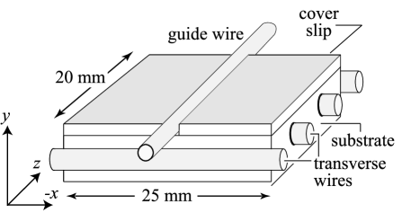
A diagram of the atom chip used to form our microtrap is shown in figure 1. The main wire is a 500 m diameter guide wire along the z-direction. It consists of a central core of copper with m radius, a m thick aluminum layer and a m thick ceramic sheath. This wire is glued by high-vacuum epoxy (Bylapox 7285) into the m-deep channel formed by a glass substrate and two glass cover slips. Below the guide wire there are four transverse wires, m in diameter. The cover slips are coated with 60 nm of gold so that they reflect 780 nm light. In order to make a Bose-Einstein condensate in the microtrap we first collect 87Rb atoms using a magneto-optical trap whose beams are reflected from the gold surface. This MOT collects atoms at a height of 4 mm above the surface and cools them to K. The MOT is pulled down to a height of 1.3 mm by passing a current of 3.2 A through the guide wire and adding a uniform magnetic field of 6 G along the x-direction. This compresses the cloud into a cylindrical shape and increases the phase space density of the atoms to jones02 .
The light and the anti-Helmholtz coils of the MOT are then switched off and the atoms are optically pumped into the state. We collect of these atoms in the magnetic guide formed by the guide wire (8 A along z), and the transverse bias field (10 G along x). Axial confinement is provided by the inner transverse wires (15 A each along -x ), and the outer transverse wires (15 A each along x ). The field at the center of this trap is partly cancelled by an axial bias field (G along z). Next, the trap is adiabatically compressed over 0.5 s by increasing and to G and G respectively, and reducing the guide current to A. This brings the trap to a distance of 225 m from the wire and raises the radial and axial trap frequencies to 840 Hz and 26 Hz. The elastic collision rate is now s-1, which is high enough for forced rf evaporative cooling to be efficient. We sweep the rf frequency logarithmically over 12.5 s from 13 MHz to a final frequency near 600 kHz. This cools the cloud down to well below the 380 nK critical temperature for Bose-Einstein condensation and produces up to atoms in the condensate jones02 .
We find that the number of atoms in the microtrap decays exceedingly slowly with time. We cannot leave the trap on long enough to measure the decay precisely because the vacuum feedthroughs that carry the trap currents overheat, causing a sudden increase of pressure after s. However, the lifetime is well in excess of 100 s. For many of our measurements we stop the evaporation after 6 s at a temperature in the range of K. These thermal clouds also have lifetimes well over 100 s.
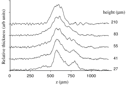
To bring the atoms closer to the surface, we smoothly reduce the current flowing in the guide wire during the last s of evaporation. The arrival of the atoms at the desired height coincides with the end of the evaporation ramp. The cloud is then viewed on a ccd camera using absorption imaging with the probe beam propagating along the x-direction. At distances above m from the surface the axial profile of the cloud (i.e. along the z-direction) is Gaussian, as shown in figure 2. However, as the cloud approaches the surface of the wire, it breaks into fragments, similar to those observed by other groups close to copper wire fortagh02 ; leanhardt02 . At a height of m, the potential wells responsible for the fragmentation shown in figure 2 are K deep and are due to a magnetic field parallel to the wire kraft02 that alternates between mG. Relative to the expected field of the wire this anomalous part is . The depth of these wells increases strongly as the cloud approaches the aluminum surface, even though it is still almost m away from the copper. This suggests that fragmentation is not peculiar to copper but applies equally to currents flowing in aluminum. Compared with references fortagh02 ; leanhardt02 , the current density in our wire is much lower, making it unlikely that the fragmentation is a result of current instability at high density, as has been suggested kraft02 . It remains an open question whether this phenomenon is due to some fundamental physics, such as arrangement of the spins in the conduction electrons fortagh02 ; kraft02 , or simply to imperfections in the geometry of the wire.
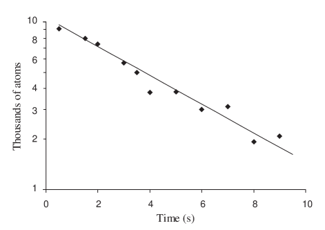
Figure 3 shows the total number of atoms in the (fragmented) microtrap versus time, measured at a height of 29(4) m above the aluminum surface of the wire. A small number of atoms is used in order to avoid the unnecessary complication of 3-body loss from the trap. This curve yields a lifetime of 5.1(0.3) s - very much shorter than the lifetime far from the wire. The increased loss rate is due to spin flip transitions driven by thermal fluctuations of the magnetic field close to the wire. The resonant frequency for this spin flip transition is , where is the Bohr magneton, is Planck’s constant, and is the magnetic field at the center of the trap, where the cold atoms reside. This field is produced by the combination of the transverse wires and the axial bias field , and it is controlled by adjusting .
Since the evaporative cooling uses these same spin flip transitions, we are able to determine the transition frequency by making several evaporations with different values of the final rf frequency. The final temperature, as measured by the mean square length of the thermal cloud, is linearly related to this final frequency. Extrapolation to zero cloud length yields the spin flip frequency of atoms at the center of the trap. The measurements shown in figure 3 were taken with MHz, corresponding to a field of G.
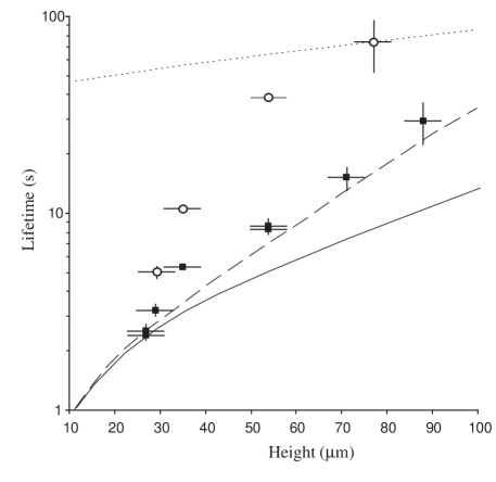
Figure 4 shows the lifetimes measured by similar decay curves at a variety of distances from the wire. There are two series of measurements using two different values of the spin-flip frequency: MHz (circles), and kHz (squares). The contribution of the transverse wires to varies slightly with height, but we have measured this and have compensated for for it by adjusting so as to maintain constant . In each series, the lifetime for atoms to remain in the trap exhibits a strong dependence on the distance from the surface, decreasing by an order of magnitude as the distance is reduced from m to m. We note that the radial trap frequency is by contrast almost constant over this height range (Hz for the larger and Hz for the smaller) because it is inversely proportional to the distance from the center of the wire. At a given height, atoms with a lower spin flip frequency have a shorter lifetime. The factor of three in produces a factor of in lifetime far from the surface. This ratio decreases closer to the surface, reaching at a distance of m.
The solid (dashed) curve in figure 4 shows the expected thermal spin-flip lifetime for rubidium atoms in the state above a thick plane slab of aluminum note1 with kHz (MHz). We have calculated these curves following Henkel et al. henkel99 , whose equation (35) gives the spin flip rate for a spin- atom. For our case, the rate-limiting transition is , which has a smaller matrix element by a factor of . Neglecting an insignificant height-independent part, is proportional to , where is the height above the surface and is the skin depth of the aluminum at the frequency of the spin flip transition. The skin depth sets a natural length scale of m (m) for kHz (MHz). Close to the surface (), and there is no dependence on because . By contrast, when , the lifetime is sensitive to and varies as . There are some points of striking similarity between our data taken above the cylindrical wire and this theory for a thick aluminum slab. First, the lifetimes we observe above the aluminum wire are slightly longer than those predicted above a plane aluminum slab. This is what one would expect, since the wire may be viewed as a slab with some of its more distant parts removed. Second, the lifetime above the wire increases a little more rapidly than the corresponding lifetime above a slab. This is a natural consequence of the additional length scale introduced by the m radius of the wire. Third, the variation with height in the ratio of lifetimes for the two different values of is echoed in the predicted behavior above a slab. We interpret these similarities as confirmation that the loss we observe is indeed due to spin flips induced by thermal fluctuations of the magnetic field above the wire.
This result has been achieved after taking considerable care to control technical noise in the currents being carried by the wires. In the bandwidth Hz - kHz, our current regulation circuits have rms noise below A, corresponding to a part per million of the dc current. At present, however, the reference voltages that control and the guide wire current are provided by waveform generators whose outputs do not have this level of stability. They increase the total noise current at audio frequencies by a factor of . We observe a heating rate in the range K/s that is thought to be the consequence of this. To look for rf technical noise close to the spin flip frequency we initially used the antenna that drives the evaporative cooling as a receiver to search for stray fields. A spectrum analyzer revealed some very weak rf signals that were removed after paying attention to ground loops and shielding. The atoms themselves then proved to be much more sensitive spectrum analyzers. With the atoms at m above the wire, a scan of revealed a resonant dip in the lifetime at approximately MHz. This was found to be from a parasitic oscillation in the optical shutter drivers that appeared while the shutters were closed. Once it was removed, no other rf radiation could be detected. If there were any residual rf current in the guide wire, the resulting field would vary as , giving a lifetime proportional to , as verified by leanhardt02a . This power law is indicated by the dotted line in figure 4, arbitrarily placed to pass through one of our data points. Clearly the height dependence we observe is much stronger than that. Spin flips induced by rf pickup cause a loss rate proportional to the rf power at the spin flip frequency . This leads to a constant ratio of lifetimes, not the height-dependent ratio that we observe.
For the short-range points presented in figure 4 we checked that the lifetime did not change when the size of the cloud was increased by raising the temperature to . We are therefore confident that the lifetimes presented here are not influenced at all by atoms hitting the surface, despite its close proximity. Presumably the BEC provides reliable spin flip data at shorter distances than the m presented here because it has a smaller radius than thermal cloud, typically m. However, we do not present any shorter range data here because we have no way other than changing the cloud size to distinguish surface loss from spin flip loss.
Atom chips aim to control quantum superposition and entanglement in neutral atoms. From this point of view, it is very undesirable that thermal fluctuations relax the atomic spins over a few seconds at a distance of m from the surface. This problem can be reduced if the metallic parts of the chip surface are restricted to being thin films. Many atom chips are made by covering a substrate with a m thick metal layer, which is then patterned lithographically. Since the fields radiated by thermal current fluctuations must propagate through the conductor to reach the atoms, we can consider that the current fluctuations of interest in a thick slab are localized within a skin depth of the surface, i.e. in a layer m thick. Hence, metal layers that are m thick generate times less noise power at these frequencies and produces a correspondingly lower spin flip loss rate. Recently we have used a different apparatus to hold rubidium atoms in a magnetic trap m away from a nm-thick gold film. We find that the thin gold film does indeed produce a much lower spin flip rate retter02 than we see here at a distance of m from the wire. Leanhardt et al., leanhardt02a have also observed long lifetimes at m from a m copper film.
Even so, the coupling between the atoms and the substrate poses an important technical difficulty for atom chips if the atoms are to approach the surface much more closely than m. One method could be to cool the chip to suppress the thermal fluctuations, and to use superconducting wire to avoid dissipating heat. An alternative is to avoid current-carrying wires altogether on the surface of the chip by using permanent magnets to produce the required microscopic structures. Videotape provides a simple way of making structures down to m in size hindsreview99 . In our laboratory we have loaded atoms into microtraps formed above sinusoidally magnetized videotape, where they can readily be cooled by evaporation and manipulated by externally applied magnetic fields retter02 ; retter03 . In order to reach an even smaller length scale, we are now exploring the use of magneto-optical films for making magnetic traps. These are metallic, but can be as thin as nm and still produce traps several mK deep a few m away from the surface.
We are indebted to Alan Butler for expert technical assistance. We also acknowledge valuable discussions with Gabriel Barton and Jozsef Fortagh. This work was supported by the EPSRC and PPARC research councils of the UK and by the ACQUIRE and FASTNET networks of the European Union.
References
- (1) J. D. Weinstein and K. G. Libbrecht, Phys. Rev. A 52, 4004, (1995).
- (2) V. Vuletic, T. Fischer, M. Praeger, T. W. Hänsch and C. Zimmermann, Phys. Rev. Lett. 80, 1634, (1998).
- (3) J. Fortagh, A. Grossmann, C. Zimmerman and T. W. Hänsch, Phys. Rev. Lett. 81, 5310, (1998).
- (4) D. Müller and D. Z. Anderson and R.J. Grow and P. D. D. Schwindt and E. A. Cornell, Phys. Rev. Lett. 83, 5194, (1999).
- (5) N. H. Dekker et al., Phys. Rev. Lett. 84, 1124, (2000).
- (6) M. Key et al., Phys. Rev. Lett. 87, 230401, (2000).
- (7) E. A. Hinds and I. G. Hughes, J. Phys. D. 32, R119, (1999).
- (8) R. Folman and P. Krüger and C. Henkel and J. Schmiedmayer, Adv. Atom. Mol. Opt. Phys 48, 263, (2002).
- (9) E. A. Hinds and C. J. Vale and M. G. Boshier, Phys. Rev. Lett. 86, 1426, (2001).
- (10) W. Hänsel and J. Reichel and P. Hommelhoff and T. W. Hänsch, Phys. Rev. A 64, 063607, (2001).
- (11) E. Andersson et al., Phys. Rev. Lett. 88, 100401, (2002).
- (12) T. Calarco et al., Phys. Rev. A. 61, 022304, (2000).
- (13) P. Horak et al., quant-ph/0210090, (2002).
- (14) J. Fortagh and H. Ott and S. Kraft and A. Gunther and C. Zimmerman, Phys. Rev. A 66, 041604(R), (2002).
- (15) A. E. Leanhardt et al., Phys. Rev. Lett. 89, 040401, (2002).
- (16) S. Kraft et al., J. Phys. B 35, 469, (2002).
- (17) A. E. Leanhardt et al., cond-mat/0211345, (2002).
- (18) C. Henkel and S. Pötting and M. Wilkens”, Appl. Phys. B 69, 379, (1999).
- (19) M. Jones, D.Phil Thesis, Sussex University,(2002).
- (20) The corresponding curves for copper are almost the same because the two metals have very similar resistivities: m for Al and m for Cu.
- (21) J. Retter, D.Phil Thesis, Sussex University, (2002).
- (22) J. Retter et al., to be published, (2003).