Decoherence control in microwave cavities
Abstract
We present a scheme able to protect the quantum states of a cavity mode against the decohering effects of photon loss. The scheme preserves quantum states with a definite parity, and improves previous proposals for decoherence control in cavities. It is implemented by sending single atoms, one by one, through the cavity. The atomic state gets first correlated to the photon number parity. The wrong parity results in an atom in the upper state. The atom in this state is then used to inject a photon in the mode via adiabatic transfer, correcting the field parity. By solving numerically the exact master equation of the system, we show that the protection of simple quantum states could be experimentally demonstrated using presently available experimental apparatus.
pacs:
03.65.Yz, 03.67.-a, 42.50.Dv, 42.50.ArI Introduction
In recent years, considerable effort has been devoted to designing strategies able to counteract the undesired effects of the coupling with an external environment. Notable examples are quantum error correction codes qecc and error avoiding codes eac , both based on encoding the state to be protected into carefully selected subspaces of the joint Hilbert space of the system and a number of ancillary systems. The main limitation for the efficient implementation of these encoding strategies for combating decoherence is the large amount of extra resources required steane . Correcting all possible one-qubit errors requires at least five qubits zurprl . This number rapidly increases if fault tolerant error correction is also considered. For this reason, other alternative approaches which do not require ancillary resources have been pursued and developed in parallel with encoding strategies. These decoherence control schemes may be divided into two main categories: open-loop viola ; ban ; noi ; agarwal ; berman ; termico , and closed-loop (or quantum feedback) strategies closed ; mabuchi ; protect ; jmr .
In open loop techniques (also called dynamical decoupling schemes), the system is subject to an external, suitably tailored, time-dependent driving. The external control Hamiltonian is chosen on the basis of a limited, a priori, knowledge of the system-environment dynamics, in order to realize an effective dynamical decoupling of the system from the environment. The main idea behind these open loop schemes originates in refocusing techniques in NMR spectroscopy waugh , but they have been recently transposed in many different contexts, such as the inhibition of the decay of an unstable atomic state agarwal , the suppression of magnetic state decoherence berman and the reduction of heating effects in linear ion traps termico . The main drawback of open loop decoupling procedures is that the timing constraints are particularly stringent. In fact, the decoupling interaction has to be turned on and off at extremely short time scales, even faster than typical environmental timescale viola ; noi ; termico . An approach to quantum state protection related to decoupling schemes is represented by reservoir engineering schemes poyatos ; lutk ; david , in which an external driving is used to create an effective reservoir for the system. In such a way, the state to be protected becomes a stationary state of the modified dynamics. Examples have been proposed for the center-of-mass motion of trapped ions poyatos ; david and for atomic internal states lutk .
It is interesting to notice that quantum error correction codes, error avoiding codes and decoupling schemes can be described in a unified framework based on the representations of the algebra of errors (the algebra generated by the set of system operators describing the effects of the environment) zana2 ; viola4 . In the error-algebra framework, quantum information is protected using symmetry. In the case of decoherence-free subspaces the symmetry naturally exists in the interaction with the environment. In the case of decoupling techniques, symmetry is induced by the added driving Hamiltonian. Finally, in quantum error correction codes, symmetry exists implicitly within the larger Hilbert space of the system and ancillae zana2 .
Closed loop techniques represented the first attempt to control decoherence closed ; mabuchi . In this case, the system to be protected is subject to appropriate measurements, and the classical information obtained from this measurement is used for real-time correction of the system dynamics. This technique shares therefore some similarities with quantum error correction, which also checks which error has taken place and eventually corrects it. However, the main limiting aspect of feedback schemes is the need of a measurement, which is always inevitably prone to errors and finite detection efficiency. For this reason, recent attempts have tried to improve these closed-loop schemes by avoiding the explicit measurement step, resorting to what may be called “fully quantum feedback” schemes, in which sensors, controller, and actuators are themselves quantum systems and interact coherently with the system to be controlled lloyd . In this case, the entire feedback loop is coherent and is not limited by measurement inefficiencies. In fact, some of us have already proposed a scheme of this kind jmr . It improved an existing closed-loop scheme for decoherence control protect , by replacing the measurement step (an atomic detection) with the coherent interaction with a quantum controller, represented by a high-Q cavity. The quantum coherent interaction allows an automatic correction of the dynamics, without needing an explicit measurement, similar to what happens in quantum error correction codes.
In this paper we proceed further along this direction by introducing a significant simplification of the “automatic” scheme of jmr . As in jmr , the present scheme is designed to protect an arbitrary quantum state of a microwave cavity mode with a given parity against the decohering effects of photon loss. However, in the present proposal, the whole feedback loop is realized by a single atom crossing the cavity. It “measures” the parity of the field in the first part of its interaction with the cavity. The atom then performs, when needed, the state correction in the second part of the interaction time. For this reason, this scheme is another example of a fully quantum feedback loop lloyd , which employs very limited resources, namely a single atom playing the roles of sensor, controller and actuator. In the scheme of Ref. jmr instead, a first atom is the sensor, a second high- cavity is the controller. A second atom is used as the actuator. The proposed strategy shares also some analogies with quantum error correction codes. The error to be corrected is the loss of one photon, which drives the state out of a parity eigenspace. With this respect, the two-level atom implementing the scheme plays the role of the error syndrome, because its state denotes the eventual presence of an error, that is, of a wrong parity.
The simplifications brought by the present scheme are relevant since they make the present proposal much easier to implement than that of jmr , because it does not need a second high- cavity and the use of a second atomic source. An easy implementation is an important asset. In spite of very many theoretical proposals for decoherence control, there has been only very few experimental demonstrations. A simple example of decoherence-free subspace immune from magnetic field noise has been demonstrated with two trapped ions in kielp , while error correction codes for single qubit errors has been demonstrated only in NMR quantum information processors nmrqecc . Outside the usual application in NMR refocusing techniques, dynamical decoupling schemes have been implemented only in Ref. bergl , where a proof-of-principle demonstration for a photon polarization qubit with artificially added decoherence has been realized (see also Ref. fortu for a recent demonstration of encoded decoupling schemes in NMR systems). A simple demonstration of fully quantum feedback has been given in the case of a three-nuclear spin system in lloyd2 , but no closed-loop decoherence control scheme has been demonstrated yet. The eventual implementation of the present proposal is important also because it would represent the first demonstration of the control of an intrinsic and unavoidable decoherence source, photon loss, instead of the control of an added noise.
The paper is organized as follows: In Section II, the cavity QED model under study is described, and the quantum state protection scheme is presented in detail. In Section III, the performance of the proposed scheme is studied by solving numerically the dynamical evolution of the system. Different examples of initial quantum states of the radiation mode to protect will be considered. Section IV is for concluding remarks.
II The state protection scheme
The general purpose of decoherence control schemes is to protect a given subspace of a system Hilbert space, and quantum coherent evolutions within it. The conditions under which these noiseless subsystems exist, and universal quantum computation within them is possible have been already illustrated in the recent literature, especially in the case of qubits viola ; zana2 ; viola4 ; vkl ; lidar . However, the experimental realization of these general schemes is difficult in many physical situations. This is particularly true in infinite dimensional systems as radiation modes, which are of fundamental importance for any quantum communication scheme and for which only few specific (and difficult to implement) quantum error correction schemes have been proposed cvqecc . Here, we shall focus on the case of a radiation mode confined in a cavity. The first examples of quantum gates and quantum state manipulations have been demonstrated in this context disp ; turchette ; cat ; noncl ; varcoe ; mani . Moreover, cavity modes could represent the nodes of a quantum network of multiple atom-cavity systems linked by optical interconnects pell .
In electromagnetic cavities, decoherence is mainly of dissipative origin and it is associated with the photon losses due to diffraction and to the transmission and absorption of the mirrors. In the general case where the reservoir of the continuum of electromagnetic modes is at thermal equilibrium at temperature , the dynamics is well described by the master equation (in the frame rotating at the mode frequency ) milwal
| (1) |
where is the field density matrix and the annihilation operator of the cavity mode, the cavity decay rate and is the equilibrium thermal photon number. The cavity mode is affected by two kinds of errors, photon loss (with rate ) and thermal photon creation (with rate ). However, in many cases, one has . Photon loss is then by far the predominant source of decoherence.
In protect , a closed-loop scheme for protecting a generic state of a cavity mode has been proposed, based on the simple idea of giving back the photon as soon as it is lost. In the case where the sensor is represented by a single-photon photodetector with quantum efficiency continuously monitoring the cavity, the dynamics in the presence of feedback is described by the master equation (in the case ) protect
| (2) |
In the case of perfect detection () cavity damping is therefore replaced by an unconventional phase-diffusion process. In the ideal case, the only well-preserved states are the Fock states. However, since the phase diffusion process is very slow, the resulting quantum state protection is still significant for other states protect .
In the case of microwave cavities, there are no efficient single photon detectors besides atoms crossing the cavity mode. The photon counting can be replaced in this case by a field parity measurementprotect ; engl ; brune96 ; lutt ; wign . This measurement can be efficiently performed by using a dispersive atom-field interaction revealed by a Ramsey interferometry set-up Ramsey . If these parity measurements are repeated at short time intervals, so that multiple photon losses between them are negligible, they reveal unambiguously the photon losses and replace a single-photon photodetector. This is precisely the stroboscopic measurement scheme proposed in protect for the cavity QED microwave experiments described in details in rmp . The price to pay when using parity measurements instead of photon counting is that only states with a given parity can be protected.
Ref. jmr improved this closed-loop decoherence control scheme by transforming it into one of the first examples of “fully quantum feedback loop”. In protect , the feedback loop involved a first atom probing the parity of the cavity mode. The final state of the first atom, correlated to the field parity, was measured by a state-selective atomic detector. Depending upon the result of this measurement, a dedicated electronics could send a second atom through the cavity. This atom would emit a photon in the mode, correcting the effect of photon loss and restoring the initial field parity. Therefore, in this case, both the sensor (first atom + detector) and the controller (the electronics) are essentially classical, while only the actuator (the second atom) is a quantum system. In jmr the detector and the controlling electronics are replaced by a second high- microwave cavity, resonantly interacting with the two atoms. This cavity becomes the controller and the feedback loop has become completely quantum. Here, we propose a further improvement of this protection scheme, making its experimental implementation easier. The present scheme is based again on the measurement of the cavity mode parity, but it involves only one atom, which, in passing through the cavity, first measures and then corrects the state of the mode when needed. The simplification of the design is evident, with a single atom realizing the whole loop, by playing all the roles of sensor, controller and actuator.
II.1 The physical system and the protection scheme in detail
The microwave cavity QED set-up which we have specifically considered for the implementation of the proposed decoherence control scheme is described in detail in rmp , in which either generation of non-classical states of the radiation cat ; noncl , and coherent quantum state manipulation mani have been already demonstrated.
A sketch of the set-up is shown in Fig. 1. Its central part is a superconducting cavity in a Fabry-Perot configuration, cooled down at about K. It sustains two Gaussian field modes with the same spatial structure and orthogonal linear polarizations. They are separated by a frequency interval kHz around GHz. The cavity modes can be driven by a tunable classical source . These two modes can interact in a controlled way with single, velocity-selected, atoms effusing from oven . The atoms are prepared one at a time in long-lived (lifetime ms), circular Rydberg states, (principal quantum number 51) and (principal quantum number 50), in box . The atoms then interact with the cavity, quasi resonant on the transition. The atom-field coupling is measured by the single-photon Rabi frequency, which is time-dependent because of the mode gaussian spatial structure. At time , the Rabi frequency writes , where mm is the mode waist, kHz rabi , and corresponds to the atom crossing the cavity axis. The detuning from the cavity mode resonance frequency, , can be changed in time in a controlled way using the Stark shift induced by a uniform electric field applied across the cavity mirrors. The two-level atom can be manipulated also through microwave pulses generated by the tunable source in a low- transverse mode. The final atomic state is recorded by the state-selective detector .
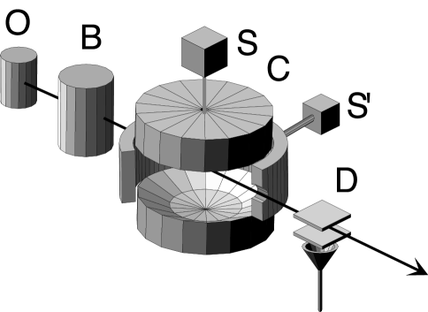
The whole protection process is realized by the atom during its transit through the cavity mode. The first part of the interaction time is used for the “measurement” of the cavity mode parity, while the second part is used for the possible state correction. A long interaction time is therefore needed, requiring atoms with a moderate velocity. We are considering here velocities around m/s, which are straightforwardly obtained in the experiments without need of atomic beam cooling wign . The feedback atoms, sent one by one, are initially prepared in the excited state . The feedback atoms are finally detected in the field ionization detector D. In a single experimental sequence, we might thus access the individual quantum trajectory of the cavity field, conditioned to the atomic detections. We are, however, interested here in an unconditional decoherence control scheme, able to preserve any quantum state with a given parity. For this reason, we assume that the information about the individual atomic state is finally discarded in the data analysis, and we thus consider only quantum averages of very many individual trajectories. Note that keeping the atomic state information and accessing to individual trajectories leads to a different, conditional, protection scheme which will be discussed elsewhere. The state of the system just before a generic atom enters the cavity is thus , where is the reduced state of the cavity mode. We consider only the cavity mode to protect, while the other quasi-resonant mode is simply a spectator mode, even though it has been taken into account in the numerical simulations described in the following Section.
The parity measurement wign is performed using a Ramsey interferometry scheme Ramsey , involving a dispersive interaction in which the transition is light-shifted by the cavity mode disp , sandwiched between two pulses mixing and before and after the dispersive interaction. The two pulses are generated by the source in a low- transverse mode in the cavity structure rmp . In order to minimize a spurious coupling of the Ramsey source with the superconducting cavity modes, the atomic transition is shifted far away from the cavity resonance by Stark effect at the time of the pulses (see Fig. 2 showing the spatial dependence of the atomic detuning within the cavity, providing a schematic description of the protection scheme). A proper pulse shape tailoring is used to decrease even further this spurious coupling wign .

The dispersive interaction between the atom and the cavity mode is obtained for sufficiently large atomic detuning, i.e., when , and for adiabatic variations of the parameters. The corresponding Hamiltonian in the frame rotating at the cavity mode frequency is then
| (3) |
The associated unitary evolution is given by
| (4) |
where and . As shown in protect ; jmr ; brune96 ; lutt , a conditional phase shift per photon equal to is needed for a parity measurement, which implies adjusting the detuning and the duration of the dispersive interaction in such a way that .
The first stage of the feedback loop, describing the parity measurement, is given therefore by the transformation
| (5) |
where . Using this fact, the state of the system after the step (c) of Fig. 2 can be rewritten as
| (6) |
It is evident that the measurement of the cavity mode parity is obtained if the phase is appropriately adjusted so that . Each atomic state is then unambiguously correlated with a parity eigenvalue. The phase can be adjusted to any desired value, by strongly detuning the atom from the cavity with a very short Stark shift pulse, which has a negligible effect on (step (d) of Fig. 2). In the second part of the interaction time, the atom is used to deliver a photon to the cavity when the “wrong” parity has been measured. The excited state has thus to be correlated with the wrong parity component. By choosing or , we can choose which kind of parity eigenstates of the cavity mode is protected against photon losses.
To be specific, we consider from now on the protection of odd cavity states. This implies choosing , so that is associated with even states. Finally, note that the overall phase space rotation of the cavity mode in Eq. (6) can be eliminated by simply adjusting the phase of the reference field in , so that the state of the system at the end of the measurement stage can be written as
| (7) |
where
| (8) | |||||
| (9) |
are the projectors onto the even and odd parity eigenspaces, respectively.
In the second part of its interaction time with the cavity, the atom corrects the cavity state component with the wrong parity, by transferring its excitation to it. As in jmr , this is done using adiabatic transfer. When the atomic detuning is adiabatically changed from a large positive to a large negative value, the system remains in the instantaneous dressed state (see jmr ), realizing therefore the transformation
| (10) |
The photon emission is thus independent of the cavity mode state, an essential feature for state-independent protection.
If the atom is in state , corresponding to a field measured to be in the “right” parity state, the opposite adiabatic transfer could take place, resulting in a spoiled parity. We have thus to get rid of the atom when it exits the parity measurement in state . This can be achieved by tuning the classical source on resonance with the transition ( is a lower circular Rydberg state with principal quantum number rmp ) and realizing a pulse . The atom is then “shelved” in state , which does not interact with the cavity mode. This prevents this unwanted transfer to occur.
The ideal adiabatic transfer can be formally described by the operator
| (11) |
so that the state of the atom-cavity mode system at the end of the atomic passage is
| (12) |
Therefore, in each cycle, the cavity mode is either projected into the correct (odd) parity eigenspace, or is corrected via adiabatic transfer when it has a wrong (even) parity. The two possibilities could be distinguished by detecting the exiting atoms respectively in or in , selecting in this way one of the quantum trajectories of the cavity mode conditional state. However, a fully quantum feedback has not to rely on the classical information provided by the atomic state detection, and it is necessarily unconditional. Therefore, we discard the information about the individual atomic state, and tracing over the atom, we get that a generic feedback cycle, i.e., a complete atomic passage, can be described by the following map for the cavity mode state
| (13) |
These are the unitary manipulations characterizing the feedback scheme. However, in practice, these manipulations act simultaneously with the decohering effect of the thermal environment described by the master equation (1), and which are responsible for the “errors” (single photon losses) that the scheme is designed to correct for. The resulting evolution is no more unitary and described by the simple map of Eq. (13). The photon losses “contaminate” the scheme, and the projections onto the parity eigenspaces will be no more exact.
III Numerical results
The performance of the proposed protection scheme under realistic conditions has been studied by solving numerically the master equation describing the dynamics of the whole system, composed by the two non-degenerate high- cavity modes and the two-level atom crossing them. We have included also the higher frequency mode (with frequency and annihilation operator ) even though we are not interested in its state. It is supposed to play only the role of a spectator in the process. However, in the apparatus described in rmp , its frequency is very close to the one of the useful mode. It could be a source of imperfections in the feedback scheme by producing uncontrolled phase shifts on the atom during the parity measurement.
We have considered the following master equation for the density operator of the whole system
| (14) |
where the superoperator has been defined in Eq. (1), and
| (15) | |||
is the total Hamiltonian of the system in the frame rotating at the frequency of the mode of interest. We assume that the atoms are sent one by one, with a spatial separation of mm. Since the cavity diameter is mm and the mode waist is mm, this guarantees that the atoms interact with the cavity mode one at a time, so that two-atoms effects are avoided. Each feedback cycle lasts exactly the time the atom takes to cross the cavity region of length mm around the cavity axis (see Fig. 2). Every cycle immediately follows the preceding one, starting with the atom entering the interaction region just when the preceding one has left it. The feedback atom is always initially prepared in state so that, at the beginning of each cycle, the state of the whole system is , where is the reduced state of the two modes at the end of the preceding cycle.
The master equation has been solved in a truncated Fock basis for both modes, using the parameter values of the experimental apparatus described in rmp (see the preceding Section). We have also assumed that both cavity modes are coupled to a thermal reservoir with mean photon number . This means that thermal excitation from the reservoir is not negligible. One might thus expect that the proposed state protection scheme, designed to correct for photon losses only, may not work properly in this case. We shall see that this is not the case because photon loss is still more than twice more probable than thermal excitation. This is enough for our feedback scheme to achieve a significant state protection.
As it has been already discussed in protect ; jmr , a crucial parameter is the ratio between the time duration of the feedback cycle (coinciding with the interaction time of the atom) and the relaxation time of the cavity mode . It is evident that this ratio has to be as small as possible. Fast atoms would be preferred. However, the feedback cycle is optimal at moderate velocities, since all the atomic manipulations have to fit within the cavity crossing time. Note that the dispersive step of the parity measurement critically depends on the interaction time. In order to fulfill the phase shift condition (), the faster the atom, the smaller the detuning . However, for small values of , the dispersive Hamiltonian [Eq. (3)] is no longer a good approximation of the total Hamiltonian of Eq. (15). The correlation between the atomic state and the cavity mode parity of Eq. (7) is thus imperfect. We have seen that the best protection results are obtained with atomic velocities within the range m/s. A clear example of quantum state protection in the case of an initial odd Schrödinger cat state, , with , is described in Fig. 3, where snapshots of the time-evolved Wigner function, both in the presence (top) and in the absence (bottom) of protection, are presented. Note that a proper experimental check of the feedback procedure would be to map out the cavity state Wigner function, using the technique demonstrated in wign .
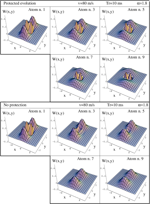
Atom refers to the first atom generating the cat state using the scheme already described in brune96 , and employed in the cat state experiment of Ref. cat . This means that, in order to be more realistic, we have always considered the protection of the effective quantum state generated by the scheme, and not of an initial, ideal, quantum state. In the peculiar case of the Schrödinger cat state of Fig. 3, the generation is obtained assuming the initial coherent state injected in the cavity by the source , and applying just the parity measurement described in the preceding Section. The odd cat state is generated by postselection, when the atom is detected in state brune96 . The elapsed time is measured (also in the case with no protection, where no atom is used) in terms of the number of crossing atoms : the time elapsed from the exit of the first atom generating the state out of the interaction region is , where mm. Fig. 3 refers to an atomic velocity m/s and a cavity mode relaxation time ms, which therefore corresponds to atomic passages. The comparison with the unprotected evolution indicates a good quantum state protection until the ninth atom, even though the decoherence time is in this case ms milwal2 , corresponding to three atomic passages. The detuning used in the dispersive stage (step (b) of Fig. 2) is kHz, while we have used a parabolic variation of the detuning around resonance for the adiabatic photon transfer (step (f) of Fig. 2) because it turned out to be the most effective one. Both the Ramsey pulses (steps (a) and (c)), and the pulse of step (e) from the source had a duration of s, with their intensity and frequency consistently tuned. The Stark shift pulse of step (d), needed to tune the phase shift so that , lasted s, with a detuning of about MHz.
A more quantitative description of the capabilities of the protection scheme is given by Fig. 4, where the time evolution of the fidelity and the parity for the odd cat state of Fig. 3 are shown at fixed atom velocity m/s, and two different values of the cavity mode relaxation time, ms. The stars connected by the dotted line refer to the protected evolution, while the diamonds linked by the full line refer to the evolution with no protection. The fidelity is appreciably improved when ms, and a small improvement can be seen even when ms. This is not surprising, because a single atomic passage lasts ms, which is equal to half relaxation time in this latter case. On the other hand, we can see that the proposed protection scheme is actually a very good parity preservation scheme. In fact, the parity of the initially generated state (atom n.1) is satisfactorily preserved in time, even in the case ms. In such a case, the initial state is far from being an ideal odd cat state because, due to photon losses, the projection onto the odd eigenspace of Eq. (9) is far from being effectively realized. With this respect, our scheme is not fault-tolerant, i.e., it does not work perfectly in the presence of losses. Not only the projections onto the parity eigenspaces, but also the adiabatic transfer in the correction stage is not perfect under realistic conditions. Its efficiency when ms is about , and it is due not only to photon losses, but also to the fact that the initial positive value of the detuning cannot be taken as large as required, because the atom would come close to resonance with the high frequency mode and transfer its excitation to it rather than to the mode to be protected.

The most recent experiments with the cavity QED apparatus described in rmp have been performed with a microwave mode with a relaxation time ms. We have however considered also longer relaxation times because there are realistic prospects to achieve somewhat longer cavity damping times soon. We have also investigated the performance of the scheme in the case of higher atomic velocities. Protection of the odd cat state remains essentially unchanged up to m/s, and clearly worsens for velocities larger than m/s. For such velocities the dispersive phase shift can be no more realized in a satisfactory way.
The scheme is suitable to protect any quantum coherent superposition with a given parity, and not only cat states. We have in fact also considered the case of an initially generated superposition of two Fock states, . The time evolution of the reduced cavity mode density matrix in the Fock basis, in the presence of the protection scheme, is compared with that with no protection in Fig. 5, considering, as in Fig. 3, ms and m/s. The other parameter values of the scheme are the same as those used in the cat state case of Fig. 3.
We have considered also in this case the protection of an initial state effectively generated within the apparatus by the first atom. The generation of the superposition state can be achieved in the following way. Initially the atom is injected in state with the cavity mode in the vacuum state (the thermal cavity field can be erased by sending through it a train of absorbing atoms rmp ). Then, a “photon pump” mechanism photpump can be used to transfer photons into the cavity mode. The atomic excitation is first transferred to the mode via a resonant atom-cavity interaction. The atom is then reset to the excited state (leaving the cavity undisturbed) by simultaneously Stark-shifting the atomic levels well out of resonance from the cavity mode, and applying a pulse on the transition . By repeating this sequence, one can generate an arbitary Fock state . In the specific case of the state , the generation sequence is: i) resonant pulse yielding ; ii) Stark-shift and classical pulse giving ; iii) classical pulse on the transition yielding ; iv) resonant interaction with the cavity, realizing the pulse while leaving the component untouched; v) Stark-shift and classical pulse giving ; vi) resonant interaction with the cavity mode giving ; vii) classical pulse on the transition yielding the state , and consequent atomic detection in state , generating the desired superposition . Note that in this case, the generation can be performed in a very short time and in our simulation, we have used a velocity m/s for the generating atom.
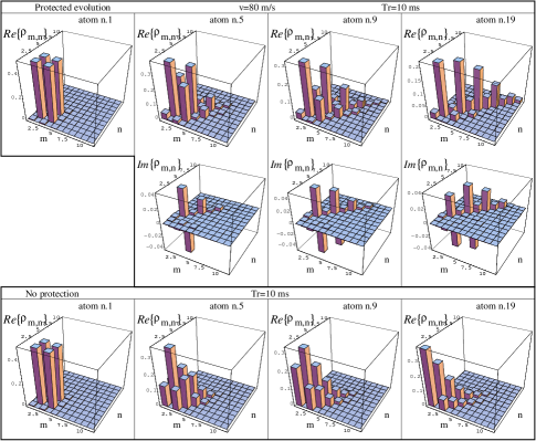
The density matrix of the protected state after atomic passages (see Fig. 5) clearly shows the effect of the feedback-induced “square-root of phase diffusion” discussed above. This phase diffusion manifests itself at long times, eventually driving the cavity mode into a stationary statistical mixture of Fock states, corresponding to a rotationally invariant Wigner function in phase space protect (see also the Wigner function of the protected state after atoms in Fig. 3, where the two Gaussian peaks start to be stretched by phase diffusion).
We have studied the time evolution of the fidelity and of the parity in this case, both in the presence (stars connected with a dotted line) and in the absence (diamonds connected by a full line) of quantum feedback (see Fig. 6). The comparison between the protected and the unprotected evolution gives results slightly better than those of the cat state (Fig. 4), because the state (especially its parity) is preserved for a longer time (up to 20 atoms when ms).

As we have seen in Section II, and it is discussed in protect ; jmr , this protection scheme is a stroboscopic version of the continuous photodetection feedback scheme described by the master equation (2). Therefore, we expect that Fock number states of the cavity mode are particularly well protected because they are unaffected by the feedback-induced phase-diffusion process. We have verified this fact in the case of the one photon Fock state and the results are shown in Fig. 7, where the time evolution of the fidelity and of the parity are shown. The first atom is very fast and generates the Fock state with a simple resonant interaction . Fig. 7 refers to a cavity relaxation time ms, and the appreciable improvement of the fidelity shows that one can demonstrate a significant protection of a Fock state using presently available experimental apparata. The state is easier to protect not only because is not affected by phase diffusion, but also because is less sensitive to the dispersive step (b) of the scheme. For this reason, we can use faster atoms and accordingly, smaller values of the detuning of step (b). In Fig. 7 we have used m/s (with kHz) and even m/s (with kHz).

Finally, it is also interesting to note that the proposed protection scheme could be even used for the generation of the Fock state. In fact, as seen in Section II, state protection is obtained by projecting and eventually restoring the component with the desired parity. If one starts from a thermal equilibrium state with a low mean photon number so that are very small for , the successive application of the protection scheme for odd states will filter out mainly the component which is obviously a stationary state of the feedback process protect .
The generation of the one photon Fock state starting from a thermal equilibrium state with initial cavity mean photon number is shown in Fig. 8, where, again, the time evolution of the fidelity and of the parity are shown (symbols are the same as those of Figs. 4, 6, and 7). In this case, there is no generation step and the first atom is used for feedback already. The plots referring to the case with no protection are obviously flat because the cavity mode is already at thermal equilibrium. As in Fig. 7, we have only considered the case with ms, and therefore the significant difference between the results with and without protection in Fig. 8 shows that Fock state filtering from an initial thermal distribution could be implemented using the available experimental apparatus. Note also that the states involved in the protection scheme are rotationally invariant in phase space, i.e., are diagonal mixtures in the Fock basis, which are less sensitive to the details of the dispersive step (b). Therefore, we have again used fast feedback atoms and consequently smaller values for the detuning of the dispersive step. We have used the same values of the single photon state of Fig. 7, m/s (with kHz), and m/s (with kHz).

IV Conclusions
We have presented a scheme for the protection of a generic quantum state of a cavity mode with a definite parity, against the decohering effects of photon losses. The scheme is a further improvement of the quantum feedback schemes described in protect ; jmr and is an example of a “fully quantum feedback” loop, where sensor, controller and actuator are all quantum system lloyd ; lloyd2 . In the present scheme, all these roles are played by a single atom crossing the cavity mode.
The scheme presents many analogies with quantum error correction codes, even though in our case, there is no explicit state encoding. In fact, the state to be corrected is already “encoded” within a parity eigenspace and the error (a single photon loss) maps this state into an orthogonal subspace, that is, that with opposite parity. Then one corrects the error only within this orthogonal subspace. In this respect, the atom plays the role of the “error syndrome” indicating the presence of the error. Finally the correction is automatically implemented only if needed, by means of a kind of C-NOT gate between the atom (control qubit) and the cavity mode (target qubit represented by the two parity eigenspaces).
We have studied the performance of the proposed feedback scheme in the case of the cavity QED set up described in rmp . We have numerically solved the exact master equation by choosing parameter values corresponding to those of rmp . The only simplification adopted is that we have assumed that the circular Rydberg atom are prepared one at a time with probability one in the set up. In other words, we have assumed a deterministic “atomic gun”. This condition is not verified by the present set up, where atomic pulses with a mean number of circular atoms per pulse are prepared. This fact would lower the efficiency of our scheme. However, this problem could be circumvented by detecting all the feedback atoms exiting the cavity and postselecting only the events with no missing feedback atom (accepting all possible atomic states).
We have considered well separated atoms ( mm) between two successive feedback cycle, just to be sure to avoid any two-atom effect. One could increase the efficiency of the protection scheme by taking closer feedback atoms. For example, if we took an atomic separation of mm, the effective feedback cycle time would be halved, and it could still be possible to keep two-atoms effects negligible.
The experimental implementation of the present scheme, especially in the simplest cases of a one photon Fock state (Figs. 7 and 8) or a superposition of Fock states (Figs. 5 and 6) is feasible with the presently available apparatus or with an apparatus with realistic improvements. Its demonstration would represent the first implementation of decoherence control schemes based on quantum feedback ideas, and also the first example of control of a very common, and almost unavoidable, source of decoherence such as photon loss.
V Acknowledgements
This work has been partially supported by the European Union through the IHP program “QUEST”.
References
- (1) P. W. Shor, Phys. Rev. A 52, 2493 (1995); A. M. Steane, Proc. R. Soc. London A 452, 2551 (1995); E. Knill and R. Laflamme, Phys. Rev. A 55, 900 (1997).
- (2) L. M. Duan and G. C. Guo, Phys. Rev. Lett. 79, 1953 (1997); P. Zanardi and M. Rasetti, Phys. Rev. Lett. 79, 3306 (1997); D. A. Lidar. I. L. Chuang, and K. B. Whaley, Phys. Rev. Lett. 81, 2594 (1998).
- (3) A. M. Steane, Nature (London) 399, 124 (1999).
- (4) R. Laflamme, C. Miquel, J.-P. Paz, and W. H. Zurek, Phys. Rev. Lett. 77, 198 (1996).
- (5) L. Viola and S. Lloyd, Phys. Rev. A 58, 2733 (1998); L. Viola, E. Knill, and S. Lloyd, Phys. Rev. Lett. 82, 2417 (1999); L. Viola, S. Lloyd, and E. Knill, Phys. Rev. Lett. 83, 4888 (1999); L. Viola and E. Knill, e-print quant-ph/0208056.
- (6) M. Ban, J. Mod. Opt. 45, 2513 (1998); L. M. Duan and G. C. Guo, Phys. Lett. A 261, 139 (1999).
- (7) D. Vitali and P. Tombesi, Phys. Rev. A 59, 4178 (1999).
- (8) G. S. Agarwal, Phys. Rev. A 61, 013809 (2000); G. S. Agarwal, M. O. Scully, and H. Walther, Phys. Rev. Lett. 86, 4271 (2001); Phys. Rev. A 63, 044101 (2001); J. Gea-Banacloche, J. Mod. Opt. 48, 927 (2001); A. G. Kofman and G. Kurizki, Phys. Rev. Lett. 87, 270405 (2001).
- (9) C. Search and P. R. Berman, Phys. Rev. Lett. 85, 2272 (2000); Phys. Rev. A 62, 053405 (2000).
- (10) D. Vitali and P. Tombesi, Phys. Rev. A 65, 012305 (2002).
- (11) P. Tombesi and D. Vitali, Phys. Rev. A 51, 4913 (1995); P. Goetsch, P. Tombesi and D. Vitali, Phys. Rev. A 54, 4519 (1996).
- (12) H. Mabuchi and P. Zoller, Phys. Rev. Lett, 76, 3108 (1996).
- (13) D. Vitali, P. Tombesi and G. J. Milburn, Phys. Rev. Lett. 79, 2442 (1997); Phys. Rev. A 57, 4930 (1998).
- (14) M. Fortunato, J. M. Raimond, P. Tombesi, and D. Vitali, Phys. Rev. A 60, 1687 (1999).
- (15) U. Haeberlen and J. S. Waugh, Phys. Rev. 175, 453 (1968).
- (16) J. F. Poyatos, J. I. Cirac and P. Zoller, Phys. Rev. Lett. 77, 4728 (1996).
- (17) N. Lütkenhaus, J. I. Cirac, and P. Zoller, Phys. Rev. A 57, 548 (1998).
- (18) A. R. R. Carvalho, P. Milman, R. L. de Matos Filho, and L. Davidovich, Phys. Rev. Lett. 86, 4988 (2001).
- (19) P. Zanardi, Phys. Rev. A 63, 012301 (2001); P. Zanardi, and S. Lloyd, e-print quant-ph/0208132.
- (20) L. Viola, E. Knill, and S. Lloyd, Phys. Rev. Lett. 85, 3520 (2000).
- (21) S. Lloyd, Phys. Rev. A 62, 022108 (2000).
- (22) D. Kielpinski et al., Science, 291, 1013 (2001).
- (23) D. G. Cory et al., Phys. Rev. Lett. 81, 2152 (1998); E. Knill, R. Laflamme, R. Martinez, and C. Negrevergne, Phys. Rev. Lett. 86, 5811 (2001).
- (24) A. J. Berglund, quant-ph/0010001.
- (25) L. Viola, E. M. Fortunato, M. A. Pravia, E. Knill, R. Laflamme, and D. G. Cory, Science 293, 2059 (2001).
- (26) R. J. Nelson, Y. Weinstein, D. Cory, and S. Lloyd, Phys. Rev. Lett. 85, 3045 (2000).
- (27) E. Knill, R. Laflamme, and L. Viola, Phys. Rev. Lett 84, 2525 (2000); L. Viola, E. Knill, and R. Laflamme, J. Phys. A 34, 7067 (2001).
- (28) D. Bacon, J. Kempe, D. A. Lidar, and K. B. Whaley, Phys. Rev. Lett. 85 1758 (2000); D. P. DiVincenzo et al., Nature (London) 408, 339 (2000); J. Kempe, D. Bacon, D. A. Lidar, and K. B. Whaley, Phys. Rev. A 63, 042307 (2001); L.-A. Wu and D. A. Lidar, Phys. Rev. Lett. 88, 207902 (2002); D. A. Lidar and L.-A. Wu, ibid., 017905 (2002).
- (29) S. L. Braunstein, Phys. Rev. Lett. 80, 4084 (1998); D. Gottesman, A. Kitaev, and J. Preskill, Phys. Rev. A 64, 012310 (2001).
- (30) M. Brune, P. Nussenzveig, F. Schmidt-Kaler, F. Bernardot, A. Maali, J. M. Raimond, and S. Haroche, Phys. Rev. Lett. 72, 3339 (1994).
- (31) Q. A. Turchette, C. J. Hood, W. Lange, H. Mabuchi and H. J. Kimble, Phys. Rev. Lett. 75, 4710 (1995).
- (32) M. Brune, E. Hagley, J. Dreyer, X. Maitre, A. Maali, C. Wunderlich, J. M. Raimond and S. Haroche, Phys. Rev. Lett. 77, 4887 (1996).
- (33) X. Maitre, E. Hagley, G. Nogues, C. Wunderlich, P. Goy, M. Brune, J. M. Raimond, and S. Haroche, Phys. Rev. Lett. 79, 769 (1997); P. Bertet, S. Osnaghi, P. Milman, A. Auffeves, P. Maioli, M. Brune, J. M. Raimond, and S. Haroche, Phys. Rev. Lett. 88, 143601 (2002).
- (34) B. T. H. Varcoe, S. Brattke, M. Weidinger, H. Walther, Nature 403, 743 (2000).
- (35) E. Hagley, X. Maitre, G. Nogues, C. Wunderlich, M. Brune, J. M. Raimond, and S. Haroche, Phys. Rev. Lett. 79, 1 (1997); G. Nogues, A. Rauschenbeutel, S. Osnaghi, M. Brune, J. M. Raimond, S. Haroche, Nature 400, 239 (1999); A. Rauschenbeutel, G. Nogues, S. Osnaghi, P. Bertet, M. Brune, J. M. Raimond, and S. Haroche, Phys. Rev. Lett. 83, 5166 (1999); Science 288, 2024 (2000); G. Nogues, A. Rauschenbeutel, S. Osnaghi, P. Bertet, M. Brune, J. M. Raimond, S. Haroche, L. G. Lutterbach, and L. Davidovich, Phys. Rev. A 62, 054101 (2000); A. Rauschenbeutel, P. Bertet, S. Osnaghi, G. Nogues, M. Brune, J. M. Raimond, and S. Haroche, Phys. Rev. A 64, 050301 (2001).
- (36) T. Pellizzari it et al., Phys. Rev. Lett. 75, 3788 (1995); J. I. Cirac, P. Zoller, H. J. Kimble, and H. Mabuchi, Phys. Rev. Lett. 78, 3221 (1997); S. J. Van Enk, J. I. Cirac, and P. Zoller , Phys. Rev. Lett. 78, 4293 (1997); Science 279, 205 (1998).
- (37) D. F. Walls and G. J. Milburn, Quantum Optics, (Springer, Berlin, 1994).
- (38) B.-G. Englert, N. Sterpi, and H. Walther, Opt. Commun. 100, 526 (1993).
- (39) L. Davidovich, M. Brune, J. M. Raimond and S. Haroche, Phys. Rev. A 53, 1295 (1996).
- (40) L. G. Lutterbach and L. Davidovich, Phys. Rev. Lett. 78, 2547 (1997); Optics Express 3, 147 (1998).
- (41) P. Bertet, A. Auffeves, P. Maioli, S. Osnaghi, T. Meunier, M. Brune, J. M. Raimond, and S. Haroche, Phys. Rev. Lett. 89, 200402 (2002).
- (42) N. F. Ramsey, Molecular Beams (Oxford University Press, New York, 1985).
- (43) J. M. Raimond, M. Brune, and S. Haroche, Rev. Mod. Phys. 73, 765 (2001).
- (44) S. Osnaghi, P. Bertet, A. Auffeves, P. Maioli, M. Brune, J. M. Raimond, and S. Haroche, Phys. Rev. Lett. 87, 037902 (2001).
- (45) D. F. Walls and G. J. Milburn, Phys. Rev. A 31, 2403 (1985).
- (46) P. Domokos, M. Brune, J. M. Raimond, and S. Haroche, Eur. Phys. J. D 1, 1 (1998).