Natural two-qubit gate for quantum computation using the interaction
Abstract
The two-qubit interaction Hamiltonian of a given physical implementation determines whether or not a two-qubit gate such as the CNOT gate can be realized easily. It can be shown that, e.g., with the interaction more than one two-qubit operation is required in order to realize CNOT. Here we propose a two-qubit gate for the interaction which combines CNOT with the SWAP operation. By using this gate quantum circuits can be implemented efficiently, even if only nearest-neighbor coupling between the qubits is available.
pacs:
03.67.LxI Introduction
It is well known that there are universal sets of quantum gates which are sufficient to perform any unitary operation on an arbitrary number of qubits. For example, it has been shown that arbitrary one-bit operations together with a non-trivial two-qubit gate provide such a set Brylinski and Brylinski (2002); Bremner et al. (2002). Clearly, in order to perform an arbitrary computation with three or more qubits the computer needs to be capable of performing two-qubit operations between arbitrary pairs of qubits.
One possible universal set of gates is the set of arbitrary one-bit operations (i.e. all unitary transformations of a single qubit) together with the two-bit controlled NOT gate (CNOT) Barenco et al. (1995). The CNOT operation is especially interesting since, to a certain extent, it can be treated as a “classical” gate originating from classical reversible computation. Gates of this type are important since there are schemes which can be transferred directly from classical reversible computation to quantum circuits. Thus the CNOT gate has become an ubiquitous reference in the design of quantum circuits. Correspondingly, the universality of a certain hardware setup is often demonstrated by providing ways how to obtain the CNOT gate (as well as arbitrary one-bit gates) by controlled manipulations of the system parameters.
Typically the formal solution for a computational task (e.g., a complex operation on several qubits, an error correction protocol etc.) is given in terms of a sequence of one-bit gates and CNOT operations. For practical reasons it is desirable to optimize these sequences according to certain criteria such as, e.g., the number of operations. On the one hand this helps to do as many computational steps as possible within a finite decoherence time, and on the other hand it renders the computation more stable with respect to computational errors.
The existence of a formal solution, however, does not mean that it can be implemented directly in a physical system. There are certain—rather general—hardware-related issues which have to be considered before. In quantum circuits for complex computational tasks it is assumed that two-qubit operations can be performed on any pair of qubits, i.e., that each qubit can be coupled with any other qubit. While for many practical implementations it is possible to couple each qubit to a few others it often appears difficult to realize a uniform (and tunable) coupling for any pair of qubits.
From a formal point of view, this is not a problem. Even if there is only nearest-neighbor coupling, two arbitrary qubits can be brought to interaction by consecutively swapping one of them with its nearest neighbor until the two considered qubits are next to each other. Then the two-bit operation is carried out and the swapping is reversed. However, from a practical point of view this workaround is rather unsatisfactory since it increases the number of operations and hence the length of the sequence considerably.
Apart from the “range of the interaction” there is another important issue related to the coupling. It depends on the microscopic coupling Hamiltonian whether or not it is easy to implement the CNOT gate (in particular, whether more than one “elementary” two-qubit gate is required to realize CNOT, see the discussion below). This seems to favor certain kinds of couplings with respect to others right from the start.
The aim of this work is to show that such hardware-related difficulties in practice may be overcome by adapting the design of the quantum circuits under consideration. While hardware properties seem to render the implementation more difficult we demonstrate that by combining just these properties an efficient implementation can be achieved. The paper is organized as follows. After introducing notations (Section II), we discuss possible interaction Hamiltonians for two qubits and the corresponding “elementary gates” (Section III). In Section IV we consider the properties of the so-called iSWAP gate in more detail. This gate appears to be a natural choice for the elementary two-qubit gate if the coupling is given by the interaction. Finally we present two examples how complex networks can be implemented efficiently for the case that only nearest-neighbor coupling is available (Section V).
II Definitions and general assumptions
To fix ideas, let us first introduce the notation which will be used throughout the paper.
Each line in a quantum circuit denotes a single qubit, the operations act on these lines from the left to the right. One-qubit gates are usually denoted by a single box with the name of the operation (i.e. the matrix ):
Special one-bit gates are the rotations about the axis
and the axis
These operations can be used to generate arbitrary one-bit operations;
we denote them by
![]() and
and
![]() .
The Hadamard
transformation can be built by using and rotations:
.
The Hadamard
transformation can be built by using and rotations:
The two-bit CNOT operation is denoted by the following symbol
Here we use the standard (computational) basis for qubits, where the basis states are ordered lexicographically, i.e., .
Finally, the SWAP gate exchanges the states of two qubits. It can be obtained by using the CNOT gate:
| (1) |
The Hamiltonian of a quantum computing device can be written as
where is the number of qubits, the first term describes the single-qubit parts and the Hamiltonians denote the interactions between the qubits. The sum is taken over all pairs of qubits which can be coupled at the hardware level. As we have mentioned before, one would like to have interaction terms for arbitrary pairs of qubits. However, often this will be difficult to realize. For example, in many of the proposed solid-state implementations nearest-neighbor coupling appears to be the standard choice (consider, e.g., electron spins in quantum dots coupled by tunnel junctions Loss and DiVincenzo (1998), excitonic qubits in quantum dots Biolatti et al. (2000), inductively coupled Josephson flux qubits Orlando et al. (1999), or Josephson charge qubits coupled by Josephson junctions Siewert et al. (2000)).
In the following we will assume that the qubits (on which arbitrary one-bit operations can be performed) are arranged in a chain or in a ring (i.e., a chain with periodic boundary conditions) with independently tunable nearest-neighbor interactions. The premise of only nearest-neighbor coupling appears to be weak enough to render the discussion sufficiently general.
III Interaction Hamiltonians for qubits
In this section we will illustrate that, depending on the available coupling term , it is more or less difficult to generate the CNOT operation. On the other hand, for each type of coupling there are two-qubit gates which can be implemented in a straightforward manner and which can be viewed as classical gates (up to one-bit operations).
Although other choices for the interaction part of the Hamiltonian are possible we will focus on three different types of couplings: Firstly, the interaction
which, e.g., can be realized for Josephson flux qubits Orlando et al. (1999) or for Josephson charge qubits coupled inductively Makhlin et al. (1999). Secondly, the or Heisenberg interaction
which basically appears in systems where spins are coupled by the exchange interaction, for example spins in quantum dots interacting via a tunnel junction Loss and DiVincenzo (1998), nuclear spins in phosphorus-doped silicon devices Kane (1998), or spin-resonance transistors Vrijen et al. (2000); and finally the interaction
This type of coupling has been proposed for quantum dot spins coupled by a cavity Imamoḡlu et al. (1999), for Josephson charge qubits coupled by Josephson junctions Siewert et al. (2000), and for nuclear spins interacting via a two-dimensional electron gas Mozyrsky et al. (2001).
For the -interaction, the CNOT operation is indeed the natural two-bit operation since
is equvialent to CNOT up to one-bit operations Makhlin (2000). As opposed to this, the Heisenberg interaction does not yield the CNOT operation directly, while
corresponds to the SWAP operation. Since SWAP cannot entangle two qubits one has to use alternative ways to produce CNOT, e.g., via the square root of SWAP (briefly denoted by ) which can be obtained by applying the Heisenberg Hamiltonian only for a time . Then CNOT can be generated Loss and DiVincenzo (1998) via
|
|
However, here has to be applied twice: the CNOT gate cannot be constructed by applying a -based gate only once Makhlin (2000). The converse is true for the construction of the SWAP operation using the interaction: while CNOT can be obtained in one step, SWAP requires two two-bit operations.
In Ref. Makhlin (2000) it was also shown that the interaction Hamiltonian can neither generate the CNOT operation nor the SWAP operation by applying an -based gate only once. Nevertheless it is sufficient to build a CNOT gate. An appropriate “elementary” two-bit gate is the iSWAP operation which is obtained by applying for a time :
It has been noted before that this gate is useful in order to generate more complex quantum operations Siewert and Fazio (2001); Kempe et al. (2001); Echternach et al. (2001).
By applying the iSWAP gate twice, the CNOT operation can be constructed
| (2) |
We mention that in complex circuits the length of this sequence can be reduced by noting that the “outer” one-bit operations partially cancel out with preceding or subsequent one-bit gates.
Of course, also the SWAP operation can be built with iSWAP gates – either by substituting Eq. (2) in Eq. (1), or by applying the following sequence (which is considerably shorter):
| (3) |
We mention that there exists also a proposal how to build the CNOT gate by using (see Ref. Imamoḡlu et al. (1999)).
The close relation between the three types of Hamiltonians and the corresponding two-bit operations has been demonstrated rigorously in Ref. Vidal et al. (2002).
IV A natural gate for the interaction
In the following we focus on the interaction. As we have seen it can be used to generate a two-qubit gate which (together with single-bit rotations) is sufficient for universal quantum computation. However, neither CNOT nor SWAP can be realized directly by using only the interaction part of the Hamiltonian, in contrast to the and the Heisenberg interaction. Now we are asking whether there exists a “natural” two-qubit operation similar to CNOT also for the -interaction, i.e. a gate which can be viewed as the quantum case of a classical reversible operation like the CNOT or the SWAP gate.
By analyzing the matrix of the iSWAP gate we see that it can be decomposed as
The second matrix represents the SWAP operation while the first matrix is equivalent to CNOT up to one-bit operations since
Thus it follows that the iSWAP gate is equivalent to a combination of CNOT and SWAP. The exact sequence is
For the sake of brevity, we introduce the name CNS (“CNOT+SWAP”) for the new gate.
Remarkably this combined gate requires only a single operation using the coupling Hamiltonian and can therefore be regarded as a natural gate in the sense explained above.
One is tempted to object that the combination of CNOT and SWAP makes the CNS gate difficult to handle. While this is true in principle, one may notice that in the case of qubit couplings only between nearest neighbors it is necessary to swap the qubit states anyhow (as we have discussed in Section I). Therefore one can try to exploit this feature by rearranging the circuit in such a way that CNOT and SWAP operations appear together and can be replaced by a CNS operation. Moreover, it should be mentioned that the CNS operation is considerably shorter than both the CNOT and the SWAP operation (realized with the coupling); so even with an overhead of two-bit operations compared to a “standard” circuit (which uses CNOT and SWAP) the rearrangement of the network may yield an advantage in terms of the operation time required for the whole sequence.
V Examples
In this section we discuss two examples in order to demonstrate that the CNS gate derived above is surprisingly powerful in efficiently implementing quantum circuits in systems with nearest-neighbor interactions. As a simple example we first discuss the Toffoli gate. In order to show that the method works for more complex networks as well, we then present an implementation of the five-bit error correction found by DiVincenzo and Shor DiVincenzo and Shor (1996).
V.1 The three-bit Toffoli gate
The three-bit Toffoli gate is the generalization of the CNOT gate with two control bits: it inverts the third bit if and only if the first two bits are in the state. It is of special interest since it is the elementary gate for classical reversible computation. For this reason it often appears in circuits for tasks that also can be solved by classical reversible computers, e.g. the modular exponentiation used in Shor’s factoring algorithm Vedral et al. (1996).
There are various proposals to implement the Toffoli gate. The shortest one using the CNOT gate as the only two-bit gate is given in Ref. DiVincenzo (1998) (which is a simplification of the version in Ref. Barenco et al. (1995)) and involves six CNOT gates (the one-bit gates are given in Appendix A):
| (4) |
We are considering systems with only nearest-neighbor interaction. As the Toffoli gate often appears as an element in a circuit with more than three qubits, interaction will be possible only between the qubit pairs 1-2 and 2-3, but not between qubits 1 and 3 (see Eq. (4)). Since in the circuit given above two of the CNOT gates are acting between qubits 1 and 3, one will have to swap one of the two qubits with qubit 2 in order to make qubits 1 and 3 nearest neighbors. This swapping has to be undone after the CNOT operation in order to bring the qubits back in the right order. Therefore one has to perform four SWAP operations in addition to the six CNOTs. The number of CNOT or iSWAP gates to build a SWAP gate is three. It turns out, however, that the CNOT operations between qubits and can be generated with only five (instead of seven) nearest-neighbor CNOTs. Thus one ends up with
-
•
CNOT gates or
-
•
iSWAP gates
required to obtain one Toffoli gate.
Now we rearrange the circuit to make use of the properties of the CNS gate. We have found the sequence
| (5) |
![[Uncaptioned image]](/html/quant-ph/0209035/assets/x24.png)
|
which replaces five CNOT operations by CNS operations and requires only a single additional SWAP operation (i.e., in addition to the sequence in Eq. (5)) to correct for the fact that the sequence does not exactly implement the Toffoli gate but rather exchanges the qubits 1 and 2 (as can be seen easily by retracing the three lines in the circuit above). For the separate SWAP three iSWAPs have to be done according to Eq. (3). Thus, one finds that the total number of iSWAP gates needed to implement the Toffoli gate in a chain of qubits is
-
•
iSWAP gates
compared to the iSWAP gates required for the “naive version” above.
Note that it is not necessarily a disadvantage to swap qubits 1 and 2 as in Eq. (5). Firstly, it can be regarded as a combination of the Toffoli gate and SWAP analogously to CNS. In fact, by replacing some of the CNOTs by CNS gates in the Toffoli network in Eq. (4) every possible permutation of the input bits can be achieved (amusingly, except the constant permutation), so one could try to exploit this in more complex circuits the same way as the fact that CNS is a combination of CNOT and SWAP.
Secondly, in quantum computing there are numerous circuits which first execute a sequence and then repeat the operations in the reverse order, e.g., to reset some ancilla qubits. In this case swapping of two qubits is often irrelevant (for examples of such circuits, see the network for the -bit Toffoli gate in Ref. Barenco et al. (1995) or the circuit of the quantum adder in Ref. Vedral et al. (1996)).
V.2 A five-bit error-correcting code
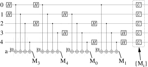
As a more advanced application where the use of CNS gates gives a considerable advantage over the simple “translation” of the network, we present an implementation of the five-bit error-correction network which was found by DiVincenzo and Shor DiVincenzo and Shor (1996). This network (see Fig. 1) can compensate arbitrary one-bit errors as long as they occur only in one of the encoding qubits at a time.
The protected qubit is encoded in five physical qubits 0 to 4 as a superposition of five-qubit states. The error correction network makes use of four ancilla bits which are initialized to before the network is applied. After carrying out the sequence of operations the ancillae are measured (in the standard basis).
While the implementation of this circuit appears rather hopeless if there is no direct interaction between the ancillae and each encoding qubit, we will show that the CNS gate makes a straightforward implementation of this network possible. To this end, we consider a setup of nine qubits (five qubits encoding the protected state plus four ancilla bits) arranged in a ring, i.e. we have nearest-neighbor couplings with periodic boundary conditions.
By properly rearranging the gates, we obtain the circuit shown in Fig. 2.
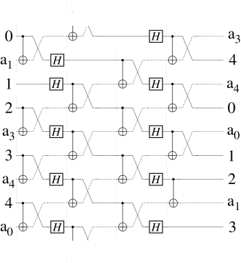
The labels 0 to 4 on the lines denote the five qubits of the error-correcting code and, correspondingly, a0, a1, a3 and a4 are the labels of the four ancilla bits for the s (see Fig. 1). After the application of the network the four ancillae have to be measured and the corresponding operations on the five bits to correct the error syndrome have to be applied. Then the ancillae have to be reset to the state. For the whole setup, only one separate CNOT is necessary, all other CNOT gates can be replaced by CNS gates. Separate SWAP operations are not required at all. One may notice that the two-bit operations in this network can be done in parallel which makes the execution of the whole sequence considerably faster 111 Formally a parallel execution looks feasible also if the network can be implemented with physical couplings between arbitrary pairs of bits, in particular between the ancillae and each encoding qubit. Note, however, that in such schemes there is typically only one channel which mediates the coupling between the various qubits Imamoḡlu et al. (1999); Makhlin et al. (1999). Consequently, simultaneous execution of several two-qubit operations would result in -qubit dynamics () which is to be excluded. Therefore, in certain cases application of nearest-neighbor coupling appears to be even more powerful than coupling between arbitrary pairs of qubits. .
The equivalence of the networks in Fig. 1 and Fig. 2 is explained in detail in Appendix B. Note that this implementation of the error-correcting code leaves the qubits in the original order, but rotates them by three bits. Therefore one has to keep track of the position of each bit. In any case, after three subsequent applications of the error correction scheme the encoding bits are back in their original order. As to the ancilla bits, their order is changed in a well-defined way. This has to be taken into account for the interpretation of the measurement outcome. After the measurement, the order of the ancillae is irrelevant since they are re-initialized to .
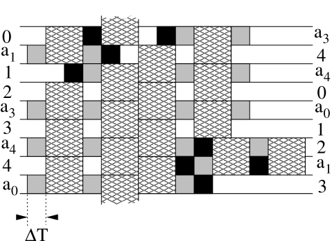
Until now, we have achieved an efficient implementation of the five-bit error-correction code using the CNS gate as an elementary building block. Let us conclude this discussion by studying the implementation closer to the hardware level. In order to realize the network in a setup of qubits with nearest-neighbor interaction, one can rewrite the circuit in Fig. 2 in terms of iSWAP operations. The sequence can be simplified considerably (see Appendix C). The result is illustrated in Fig. 3. If we assume that the energies in the one-bit and two-bit part of the Hamiltionan are of the order and , respectively, the total operation time of the sequence (without measurement, correction step and resetting the ancillae) is .
We mention that efficient solutions for similar tasks in error correction have been developed also in Refs. Braunstein and Smolin (1997); Burkard et al. (1999).
VI Conclusions
A considerable part of the research efforts in quantum computation is devoted either to the development of quantum circuits to formally solve a given computational task (one could call this sector ‘development of algorithms’), or to the practical implementation of specific algorithms for a given type of hardware. We have studied questions residing in the domain of problems between these two sectors. We have focused on aspects which are common to different types of hardware and which may affect the feasibility of the practical implementation of existing formal solutions.
In particular we have discussed two hardware-related problems which seem to render the physical implementation of quantum networks difficult: i) coupling between arbitrary pairs of qubits cannot be achieved for all hardware proposals; ii) depending on the implementation, certain two-qubit gates are more or less difficult to realize.
While at first glance these hardware properties seem to imply that hardware for quantum computation has to meet very specific demands that are hard to realize, our results indicate a much more optimistic conclusion. We have demonstrated that the interaction—which is neither capable of realizing a CNOT nor a SWAP gate directly—is surprisingly powerful in implementing certain quantum networks. This has been achieved by realizing that the CNS gate is a combination of the CNOT gate and the SWAP operation which can be obtained with a single two-qubit step.
Moreover, our examples illustrate that this gate overcomes the problems arising from the hardware property i) mentioned above in a natural way. The built-in SWAP makes an efficient implementation possible even if only nearest-neighbor interaction between the qubits is available. This approach may devise ways how to tackle this difficulty also for other types of two-qubit interactions. Interestingly, our solutions display the possibility of parallel execution of operations at the hardware level. Finally we mention that the same methods work equally well also for networks other than those presented in this article. Similar solutions can be found, e.g., for the Quantum Fourier Transform (see, e.g., Ref. Cleve et al. (1998)), for the quantum adder described in Ref. Draper (2000) (which is adding two quantum numbers), or for an adder which is adding one classical to one quantum number Beauregard (2002). This suggests the applicability of the ideas presented here for a wide range of quantum networks.
Acknowledgement
We are grateful to J. L. Dodd for pointing out to us Ref. Brylinski and Brylinski (2002).
Appendix A One-bit gates used for the Toffoli gate
The one-bit gates which were used for the three-bit Toffoli gate in Section V.1 are (up to normalization factors):
Appendix B Equivalence of the error correcting networks
We need to show that the two error correction circuits in Fig. 1 and Fig. 2 are equivalent, i.e., that they correspond to the same unitary. To this end we note that gates which have no bits in common commute trivially. Further, two subsequent CNOT operations commute if they act on the same target bit (in our case this means that they have the ancilla in common). Also two CNOT gates with the same control bit and different targets commute as long as the control bit is not modified by a single Hadamard operation between them.
Starting from these observations, the question whether the two error correcting networks are identical reduces to proving that the two marked blocks in
![[Uncaptioned image]](/html/quant-ph/0209035/assets/x28.png) |
(6) |
do commute.
This can be seen as follows. First, choose the Hadamard transformed basis for the ancillae (we will denote them by ). In this basis, the CNOT gates originally enclosed by Hadamard operations become CNOTs with control and target reversed, i.e., controlled operations. The other CNOT gates turn into controlled phase flips (i.e., controlled operations), analogously. Thus, the network in Eq. (6) corresponds to
| (7) |
In this representation, it becomes obvious that the two blocks indeed do commute: if at least one is zero, one of the two controlled operations on each qubit and is the identity, and the operations commute. On the other hand, if , exchanging and on one bit results in a global minus sign. Changing the order of the two blocks in Eq. (7) corresponds to two simultaneous changes of this kind and leaves the all-over result unchanged. Therefore, the networks in Fig. 1 and Fig. 2 are identical.
Appendix C Simplifications for circuits with iSWAP
In this appendix, we briefly describe the methods which can be used for the simplification of a network like the one presented for the five-bit error correction circuit in Section V.2. We will consider rotations about the and the -axis, and the iSWAP operation as the basic building blocks for the implementation. All other operations will be expressed in terms of these operations. Although the application of the ideas is rather straightforward it is difficult to provide formal recipes how to use them.
1. One-bit simplifications. First, rotations about the same axis can be collected, e.g.:
Clearly, rotations by an angle of can be dropped. Operation time can be saved by applying a rotation instead of a one.
A more sophisticated problem is the simplification of compound expressions of and -rotations. To this end, the following ways to express the Hadamard transformation are useful:
By choosing the appropriate way to represent the Hadamard transformations in the network (or by sometimes “artificially” creating one of these triples, for example by inserting a pair of operations whose product is unity) and replacing it by another one, considerable simplifications can be achieved. The applicability of these simplifications becomes particularly apparent if the single-bit operations are considered in the context of two-bit operations.
2. Two-bit simplifications. There is essentially only one way to simplify two-bit expressions for circuits containing iSWAP:
i.e., -rotations “commute” with iSWAP if simultaneosly the -rotation is flipped to the other qubit.
3. Ancilla simplifications. Finally, one can apply also one-bit simplifications to the ancilla bits which are possible due to the fact that we know the initial state of the ancilla and, moreover, the ancillae are measured in the basis at the end.
At the beginning of the error-correction sequence, the ancillae are set to . Therefore, -rotations immediately after the initialization can be omitted (since global phases are not important).
Further, let us assume the ancilla is in the state just before the measurement. As the measurement is performed in the basis, a rotation before the measurement would not affect the result. Therefore, also these rotation need not be considered.
References
- Brylinski and Brylinski (2002) J.-L. Brylinski and R. Brylinski, in Mathematics of Quantum Computation, edited by R. Brylinski and G. Chen (Chapman and Hall/CRC Press, 2002), eprint quant-ph/0108062.
- Bremner et al. (2002) M. J. Bremner, C. M. Dawson, J. L. Dodd, A. Gilchrist, A. W. Harrow, D. Mortimer, M. A. Nielsen, and T. J. Osborne, Phys. Rev. Lett. 89, 247902 (2002), eprint quant-ph/0207072.
- Barenco et al. (1995) A. Barenco, C. Bennett, R. Cleve, D. DiVincenzo, N. Margolus, P. Shor, T. Sleator, J. Smolin, and H. Weinfurter, Phys. Rev. A 52, 3457 (1995).
- Loss and DiVincenzo (1998) D. Loss and D. DiVincenzo, Phys. Rev. A 57, 120 (1998).
- Biolatti et al. (2000) E. Biolatti, R. Iotti, P. Zanardi, and F. Rossi, Phys. Rev. Lett. 85, 5647 (2000).
- Orlando et al. (1999) T. P. Orlando, J. E. Mooij, L. Tian, C. H. van der Wal, L. S. Levitov, S. Lloyd, and J. J. Mazo, Phys. Rev. B 60, 15398 (1999).
- Siewert et al. (2000) J. Siewert, R. Fazio, G. M. Palma, and E. Sciacca, J. Low. Temp. Phys. 118, 795 (2000).
- Makhlin et al. (1999) Y. Makhlin, G. Schön, and A. Shnirman, Nature 398, 305 (1999).
- Kane (1998) B. Kane, Nature 393, 133 (1998).
- Vrijen et al. (2000) R. Vrijen, E. Yablonovitch, K. Wang, H. W. Jiang, A. Balandin, V. Roychowdhury, T. Mor, and D. DiVincenzo, Phys. Rev. A 62, 012306 (2000).
- Imamoḡlu et al. (1999) A. Imamoḡlu, D. D. Awschalom, G. Burkard, D. P. DiVincenzo, D. Loss, M. Sherwin, and A. Small, Phys. Rev. Lett. 83, 4204 (1999).
- Mozyrsky et al. (2001) D. Mozyrsky, V. Privman, and M. Glasser, Phys. Rev. Lett. 86, 5112 (2001).
- Makhlin (2000) Y. Makhlin (2000), eprint quant-ph/0002045.
- Siewert and Fazio (2001) J. Siewert and R. Fazio, Phys. Rev. Lett. 87, 257905 (2001).
- Kempe et al. (2001) J. Kempe, D. Bacon, D. P. DiVincenzo, and K. Whaley, Quantum Inf. Comput. 1, 33 (2001), eprint quant-ph/0112013.
- Echternach et al. (2001) P. Echternach, C. P. Williams, S. C. Dultz, P. Delsing, S. Braunstein, and J. P. Dowling, Quantum Inf. Comput. 1, 143 (2001), eprint quant-ph/0112025.
- Vidal et al. (2002) G. Vidal, K. Hammerer, and J. I. Cirac, Phys. Rev. Lett. 88, 237902 (2002), eprint quant-ph/0112168.
- DiVincenzo and Shor (1996) D. DiVincenzo and P. Shor, Phys. Rev. Lett. 77, 3260 (1996).
- Vedral et al. (1996) V. Vedral, A. Barenco, and A. Ekert, Phys. Rev. A 54, 147 (1996).
- DiVincenzo (1998) D. DiVincenzo, Proc. R. Soc. London A 454, 261 (1998).
- Braunstein and Smolin (1997) S. L. Braunstein and J. A. Smolin, Phys. Rev. A 55, 945 (1997).
- Burkard et al. (1999) G. Burkard, D. Loss, D. P. DiVincenzo, and J. A. Smolin, Phys. Rev. B 60, 11404 (1999).
- Cleve et al. (1998) R. Cleve, A. Ekert, C. Macchiavello, and M. Mosca, Proc. R. Soc. London A 454, 339 (1998).
- Draper (2000) T. G. Draper (2000), eprint quant-ph/0008033.
- Beauregard (2002) S. Beauregard (2002), eprint quant-ph/0205095.