Quantum state conversion
by cross-Kerr interaction
Abstract
A generalized Mach–Zehnder-type interferometer equipped with cross-Kerr elements is proposed to convert -photon truncated single-mode quantum states into (+1)-mode single-photon states, which are suitable for further state manipulation by means of beam splitter arrays and ON/OFF-detections, and vice versa. Applications to the realization of unitary and non-unitary transformations, quantum state reconstruction, and quantum telemanipulation are studied.
PACS numbers: 03.65.Ta, 03.65.Ud, 03.65.Wj, 03.67.Hk, 03.67.Lx
1 Introduction
As a consequence of photon number conservation, the cross-Kerr interaction offers an ideal playground for quantum state engineering, and a number of applications have been studied, such as quantum non-demolition measurement, quantum state preparation and detection, quantum teleportation, and the implementation of quantum logic gates. The following examples reflect this variety of fields touched upon. A theoretical study of quantum non-demolition measurement of the photon number of two optical modes based on cross-Kerr couplers in combination with a Mach-Zehnder-interferometer is carried out in [1]. In [2], an experimental review with emphasis on back-action evading measurements on optical soliton pulses propagating in fibers is given. The preparation of Schrödinger cat-like states by employing the cross-Kerr interaction in conditional measurement is discussed in [3], including a study of the effect of damping. In [4], the use of a ring cavity equipped with a cross-Kerr element and an ON/OFF-detector with arbitrary efficiency is proposed to project a desired Fock state out of a coherent state, and in [5] a chain of such ring cavities is used to measure the photon number statistics of a signal. In [6], a realization of a Bell state measurement based on the cross-Kerr interaction is suggested and its application to teleporting the polarization state of a photon investigated. In [7], a fibre-optic non-linear Sagnac interferometer working as an optical switch is analysed and its application as an optical regenerator examined. The implementation of a quantum phase gate operating on two polarization qubits is considered in [8]. Entanglement purification generating maximally entangled states from Gaussian continuous entangled states by applying cross-Kerr interactions in conditional measurement is studied in [9].
Within classical optics, the cross-Kerr interaction is described as a third-order deviation from linearity of the polarization induced in a medium by an electric field, so that strong fields are expected to be required for its observation. In contrast, setups discussed within quantum optics and quantum information processing often operate with superpositions of low-excited Fock states. An enhancement of the “classical” nonlinearity is therefore required for its applicability in the domain of weak fields. Quantum effects such as electromagnetically induced transparency could offer a way to realize this enhancement [10]-[13]. An alternative are proposals entirely based on the nonlinearity hidden in the quantum measurement process [14].
In the present article we assume an interaction of the form with and show that it can be used, in combination with beam splitter arrays and ON/OFF-detectors, to convert -photon truncated single-mode quantum states into (+1)-mode single-photon states and vice versa. Such a converter offers novel possibilities of arbitrary single-mode quantum state engineering. As potential applications, we consider the realization of unitary and non-unitary operators, overlap measurements with orthogonal and non-orthogonal sets of states [15], and quantum telemanipulation. In general, it should be noted that finite dimensional quantum systems play an important role in the study of basic quantum state engineering and detection techniques [15]-[17].
An ON/OFF-detector is a photodetector able to distinguish between presence and absence of photons and may be realized by an avalanche-triggering photodiode. Since the total photon number of single-photon states is one, the detection of presence of photons can be done with any (non-zero) quantum detection efficiency. Placing emphasis on the main principle, we will however assume unit detection efficiency throughout the work.
The article is organized as follows. After introducing quantum state conversion in section 2, a proposal of its practical implementation is made in section 3. Application to quantum-state engineering is considered in section 4. Sections 5 and 6 are devoted to applications to quantum-state measurement and quantum telemanipulation respectively. Finally, a summary and some concluding remarks are given in section 7.
2 Quantum state conversion
Let be an arbitrary quantum state in a source Hilbert space and the operator that, as a result of a measurement with outcome , converts into a state in an isomorphic target Hilbert space according to
| (1) |
where
| (2) |
is the corresponding success probability, and the operators must resolve the identity in the source space, .
In what follows we restrict our attention to the source space spanned by the -photon single-mode states , where , and the target space spanned by the (+1)-mode single-photon states defined by . Isomorphic mapping can be realized if
| (3) |
Each state in and each operator acting on a state in can then be related to their counterparts and in , respectively, according to
| (4) |
| (5) |
and vice versa.
It is well known [18] that by combining U(2)-beam splitters to an array one can construct a 2(+1)-port which may be described by a transformation operator obeying
| (6) |
where the can form any U(+1)-group matrix. In , acts therefore as an arbitrary unitary operator
| (7) |
Moreover, measurement-assisted state preparation in only requires ON/OFF-detectors, which suggests that quantum-state engineering may be easier in than in . In order to subject a state in to a desired transformation, it could therefore be of advantage to convert it first into the corresponding state in , then to transform it there, and eventually the transformed state is converted back into a state in an isomorphic single-mode space .
3 Implementation of a quantum-state converter
3.1 Conditional operation
Let us combine two -port beam splitter arrays and to a -port Mach–Zehnder interferometer and place inside cross-Kerr couplers, which realize the transformations
| (8) |
as shown in figure 1.

The action of the whole device becomes
| (9) | |||||
where
| (10) |
describes a -port beam splitter array acting in as a unitary operator
| (11) |
The decomposition (11) reveals that the eigenvalues can be controlled by the strengths of the cross-Kerr interactions and the eigenbasis by the parameters of the beam splitter array . Thus can take the form of any unitary operator in . Let us choose
| (12) |
In this case, takes the form of
| (13) |
where . Note that the single-mode counterpart is the unitary Pegg–Barnett phase operator [19].
Next, let us specify in more detail the states of the modes and the measurements to be performed (figure 2).

In figure 2(a), each of the outgoing -modes of device is coupled to a -mode according to
| (14) |
by means of +1 separate beam splitters . From (14) it follows that
| (15) |
as is shown in the appendix. The incoming -modes of device are prepared in the state , while the incoming -modes are prepared in vacuum states. If the outgoing -modes are detected in vacuum states while the outgoing -mode of device is detected in a state , then the combined setup converts, according to (1), a -input state of the -mode into a -output state of the -modes, where the transformation operator can with (15) be written as
| (16) | |||||
We assume that none of the Fock expansion coefficients of disappears,
| (17) |
and choose
| (18) |
Note that the term has been introduced to obtain , thus ensuring the feasibility of the beam splitter transmittances needed. Applying (9) and (13), we see that (16) takes the form of (3),
| (19) |
and the joint probability (2) of detecting vacuum states as well as the state becomes
| (20) | |||||
In figure 2(b), the device runs backwards, i.e., the output ports are used as inputs, replacing detection of a given state with its preparation and vice versa. These changes are described by replacing (16) with its adjoint. That is, if the incoming -mode is prepared in the state and the incoming -modes are prepared in vacuum states, while the state is measured by detecting photon presence in the outgoing -channel, then a -input state of the -modes is converted, according to (1), into a -output state of the -mode, where the transformation operator now becomes
| (21) |
with the corresponding probability (2) of detecting photon presence in the outgoing -channel being again
| (22) | |||||
Let us now address the question of maximising the probabilities (20) and (22) by a suitable choice of . Because of , we have
| (23) |
where
| (24) |
is a Pegg–Barnett phase state. Comparing (23) with (20) and (22), we see that for the state (24), the maximal success probability is achieved. At the same time, (18) reduces to , so that the term in (16) depending on the beam splitters reads
| (25) |
and the ON/OFF-detectors D in figure 2(a) become redundant. Note that (25) acts in as a unitary operator .
3.2 Unconditional operation
Let us have a look at figure 2(a) and assume that a device DΦ is applied performing a phase measurement such that at each trial some Pegg–Barnett phase state (24) is detected in the outgoing -mode of device . Devices accomplishing detection (or preparation) of states may be constructed based on the proposals made in [20]-[25]. From (18) it follows that the action of the beam splitters reduces to (25) and the ON/OFF-detectors D can therefore be removed. The possibility of a post-measurement implementation of an operator defined by (25) according to the respective phase value measured allows us to achieve the desired state transformation irrespective of . In this way, each trail results in the desired state conversion. This can be described according to (1) if we use in place of (19) an effective transformation operator
| (26) |
which includes the effect of post-measurement adaption applied. Accordingly, the respective success probability (2) becomes .
Consider now figure 2(b) with the incoming -mode prepared in the phase state , so that (18) gives =1 and the beam splitters can be removed. Obviously, at each trial, one of the ON/OFF-detectors D clicks. The probability (22) of a click in channel and with it a successful state conversion becomes . In general however, an ON/OFF-detector in an arbitrary channel clicks, and instead of (21) we have
| (27) |
If , the ill-transformed output state may now be reconverted into its counterpart in [e.g. by feeding it back into the device using a mirror and running the setup as shown in figure 2(a)]. After subjecting it to a unitary transformation (implemented by a beam splitter array in the -channels), the original input state is reobtained. By feeding it again back into the setup figure 2(b) (e.g. by using another mirror in the -channels), we can start a new trial of state conversion. This procedure of bouncing the signal forward and backward is continued until eventually the ON/OFF-detector in channel clicks. The average number of trials needed until this happens is +1. In this way, each -input state of the -modes is sooner or later properly converted into its -counterpart of the -mode. This can again be described according to (1) if we use in place of (21) an effective transformation operator
| (28) |
which includes all the procedures applied. Again, the respective success probability (2) becomes . In summary, we see that the setups figure 2 allow in principle a reversible conversion between states in the single-mode space and their counterparts in the multi-mode space .
4 Application to quantum state engineering
4.1 Conditional operation
Let us now consider the problem of realizing an arbitrary unitary or non-unitary transformation of a single-mode state into another single-mode state according to (1). For this purpose, we combine the two state converters in figure 2 with two -port beam splitter arrays and and beam splitters , as shown in figure 3. Since detection of a state (24) is assumed in the right-hand converter, the action of the separate beam splitters (and ON/OFF-detectors) in figure 2(a) reduces to (25), and since preparation of the state (24) with is assumed in the left-hand converter, the separate beam splitters in figure 2(b) are left out.

The detection of photon presence in the outgoing -channel of the left-hand converter is equivalent to the detection of the state , so that, on measuring the state in the single-mode output channel of the right-hand converter and using the state as the single-mode input of the left-hand converter, the single-mode input state is related to the single-mode output state according to (1), where
| (29) | |||||
Here, we have set with
| (30) |
acting in as an operator
| (31) |
In the first line of (29), we can replace with
| (32) |
and introduce , which, together with (19) and (21), gives the second line of (29). The decomposition (31) reveals that the eigenbasis of can be controlled via the beam splitter array , while the eigenvalues can be varied by the transmittances of the +1 beam splitters in the dashed-line parentheses. In particular, by choosing the to be positive real, , with the extra condition , takes the form of any desired density-type operator. Assume now that there is the task of implementing the state transformation (1) associated with a given operator acting in . Its polar decomposition (the unitary operator is unique if has an inverse) can for be written as
| (33) |
where ) and
| (34) |
is the product of an SU(+1)- and a density-type operator. By identifying (34) with (32), we see that any desired state transformation (1) defined by a given operator can be implemented. here serves as normalized representant of the class of all operators differing by multiplication with a c-number factor but giving rise to the same state transformation (1).
The factor however alters the success probability (2). Since we are not restricted to the extra condition , we may therefore choose the in order to maximize this probability, i.e., the joint probability
| (35) | |||||
( ) of detecting photon presence in the outgoing -channel and measuring the state . We see that depends in general on the input state and may even identically vanish for certain inputs. (The case corresponding to for which this happens for all input states has been excluded.) Two types of state transformations are of special interest:
-
(i)
Unitary transformations.
They are obtained by choosing the values of the to be identical, , so that (32) reduces to , while the success probability (35) becomes independent of the input state, . Of particular interest is the case , allowing removal of the , thus simplifying the setup while the same time the success probability is maximized.
-
(ii)
Projective transformations.
They are obtained by choosing , so that (32) reduces to a positive operator, , and confining the allowed values of the to and some given , so that . Of particular interest is the case , leading in (29) to
(36) ( ). The output state then becomes independent of the input state , since in this case a projection onto the state is performed, and the success probability (35) reads
(37)
4.2 Unconditional operation
So far, attention has been limited to the event of detecting photon presence in the outgoing -channel of the left-hand converter as well as a detecting in the right-hand converter a phase parameter given by the beam splitter array . Alternatively, we may apply an depending on the respective value measured and, if photon presence has been detected in one of the -channels of the left-hand converter, apply the procedure described in section (3.2) to obtain unconditional convertion into . These additional procedures are taken into account by using in place of (29) an effective transformation operator
| (38) | |||||
and in place of (35) we obtain
| (39) | |||||
as the probability of detecting photon presence in one of the -channels of the left-hand converter. In particular, if the beam splitters in dashed parentheses in figure 3 are removed, , then at each trial, one of the ON/OFF-detectors D clicks, . In this way, any unitary transformation can be realized unconditionally.
5 Application to quantum-state measurement
5.1 Conditional operation
We now consider the scheme in figure 3 with the incoming -mode of the left-hand converter prepared in the vacuum state instead of . In the event of registering photon presence in the channel and detecting the state in the single-mode output channel of the right-hand converter, (29) is replaced with
| (40) | |||||
and the corresponding joint probability of registering photon presence in channel and the state in the right-hand converter is given by
| (41) | |||||
In this way, on recalling that may be defined by its action on the basis states , the overlaps of a state with the members of an arbitrary set of states , , can be measured.
Of special interest is again the case when for all (figure 3 without the beam splitters in the dashed parentheses), so that . The probability of detecting photon presence in the channel conditioned on the measurement of thus becomes
| (42) |
where follows from (20). In this way, the overlaps of the input state with states , , forming an orthonormal basis controlled by can be measured.
Measurements in two orthonormal bases are necessary to determine the expectation value of a given operator acting in . This is seen from its Cartesian decomposition into the Hermitian operators and . Inserting the spectral decomposition of and , we obtain
| (43) |
where the and are the eigenvalues and eigenstates of (=0) and (=1), respectively. An example is , for which so that is determined by measurements in the channels and alone, which are coupled by a symmetric beam splitter defined by . Repeating these measurements for different and allows us to reconstruct the input state from its matrix elements in the Fock basis.
The task of determining an unknown input state may also be accomplished experimentally, without a subsequent reconstruction from measured data. This is seen from (42). Under variation of , becomes extremal iff is an eigenstate of [26]. On the other hand, cannot be greater than the greatest eigenvalue of . We implement according to
| (44) |
as a chain of -port beam splitter arrays coupling the channels to each other, and start by tuning until the detector signal obtained in channel is maximal. [The term detector signal in a given channel is here used for the relative frequency of clicks obtained with the ON/OFF-detector in this channel given the detection of under repetition of the experiment which approximates the probability .] With regard to the operator obtained in this way, the eigenvalue equation
| (45) |
holds for =0. We now keep fixed and tune until the detector signal obtained in channel is maximal. With this new resulting tuned overall operator (44), the eigenvalue equation (45) holds for =0,1. This procedure is continued until all beam splitter arrays , , are tuned and (45) holds for all . With the resulting operator , we can now write the input state as
| (46) |
where the are the respective maximized detector signals obtained in channel . These are the eigenvalues of in descending order. Note that in this way, the input state has been diagonalized experimentally in the basis defined by the channels, because the multi-mode state entering the ON/OFF-detectors in figure 3 reads , where is the converted state leaving the multi-mode output port of the right-hand converter, i.e., exiting the array .
On the other hand, the cannot be smaller than the smallest eigenvalue of , so that, instead of maximizing, we may equally well successively minimize the detector signals . With these minimized detector signals and the operator resulting from this procedure, we can write the input state again in the form of (46), where the are now the eigenvalues of in ascending order. However, the maximizing procedure has the advantage that the maximized detector signal obtained after the first step gives us information about the purity of the input state . If for the maximal value holds, then the input is pure, , and if comes close to one we may stop the procedure after few steps if only approximate knowledge about is desired.
There is also the possibility of a quantum non-demolition measurement of pure and almost pure states. To see this, consider the situation as described by (36) and (37). After tuning such that the probability (37) has become maximal, (36) realizes a “purification” of the single-mode input state while the optimized probability (37) tells us the overlap (fidelity) between (the unknown) input state and the (known) output state .
5.2 Unconditional operation
Again, we may apply an depending on the respective value measured, instead of considering only such events in which some fixed phase value has been detected. In place of (41) we therefore now have
| (47) | |||||
In this way, the measurement time can be reduced by the factor +1.
6 Application to quantum telemanipulation
6.1 Conditional operation
Consider the setup figure 3. The initial state of the incoming -mode of the right-hand converter is destroyed, whereas an engineered state of the spatially separated outgoing -mode emerges at the left-hand converter. This switch from mode to mode is described in (29) by the operator , which represents an isomorphism between the single-mode spaces and . To operate the scheme it is not essential at which side the single-photon state is prepared and at which it is detected. This is illustrated in figure 4, in which the output ports of the optical components in figure 3 are used as input ports and vice versa. Moreover, is replaced with .
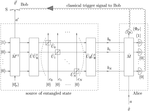
Instead of (29), we now have
| (48) | |||||
( ). Comparing (48) with (29), we see that the only change that must be made when going from figure 3 to figure 4 is replacing with its complex conjugate . However, the setup in figure 4 performs, in contrast to that in figure 3, the state engineering as a conditional teleportation. This is seen by distinguishing between Alice, Bob, and the entangled state source as shown in the figure. Bob operates an optical shutter S letting his signal prepared in the output state pass only if he has received a classical trigger bit from Alice confirming the detection of the states and in the respective output channels of her state converter. The beam splitter arrays and the left-hand converter in figure 4 can be regarded as forming the source of the entangled state with a multi-mode output to Alice and a single-mode output to Bob. Since Bob’s state can differ from Alice’s state by an arbitrarily chosen (unitary or non-unitary) transformation, the scheme combines teleportation and state engineering. In this sense, we may adopt the term “telemanipulation”. Clearly, when the source of the entangled state only consists of the left converter, so that , (48) reduces to the mode switch operator mentioned in the beginning, , and Bob’s state becomes a copy of Alice’s state.
In order to investigate the differences between the schemes figure 3 and figure 4 we now remove the device in both setups and consider the reduced single-mode states and which are obtained at the - and -output ports in that case. We start with figure 3. At the single-mode output of the right-hand converter we obtain
| (49) | |||||
and at the single-mode output of the left-hand converter ( )
| (50) | |||||
where and with given in (29). We see that both states depend on the input state . If we remove the components between the converters, so that , then (50) coincides with (49), . If in particular the input state is a mixture of Fock states, , we obtain additionally , so that (49) and (50) are two identical copies (“clones”) of the input state in this case.
We now turn to figure 4 which gives at the single-mode output of the right-hand converter ( )
| (51) | |||||
where and furthermore . We see that still depends on the input state. In particular, for , (51) turns into (49). On the other hand, the input can even pass the right converter without disturbance, , if is a projector onto the state , . However, in contrast to figure 3, the reduced state at the single-mode output of the left-hand converter,
| (52) | |||||
is now independent of the input state . Bob is left with “white noise” if Alice refuses to communicate with him.
6.2 Unconditional operation
Until now, we have assumed that Alice sends a classical trigger bit to Bob in case she has detected photon presence in channel as well as a given value of the phase defined by the construction of the entangled state source and Bob then opens the shutter S. Consider now an alternative situation in which, after detection of photon presence in some channel , Alice uses the classical channel to tell Bob the respective channel number and phase value measured. (48) is then generalized to
| (53) | |||||
where depends on the values and detected. On Bob’s side, the shutter S is replaced with state converters described in section (3.2). Bob uses these to convert his respective output state into its multi-mode counterpart, to which a unitary transformation is applied by means of a beam splitter array, and eventually the transformed state is converted back into its single-mode counterpart. In order to describe the transformation of Alice’s state into Bob’s modified state according to (1), we use in place of (53) an effective transformation operator
| (54) | |||||
which depends on and if . In particular, if the beam splitters in dashed parentheses in figure 4 are removed, , then at each trial, one of the ON/OFF-detectors D clicks, . A well known example is the unconditional teleportation, which is achieved by removing also the beam splitter array , so that (54) reduces to .
7 Conclusion
We have suggested a cross-Kerr interaction based device allowing conversion between single-mode states truncated at some photon number and (+1)-mode states whose total photon number is one. As possible applications with regard to single-mode states, we have considered the implementation of unitary and non-unitary transformations, overlap measurements with orthogonal and non-orthogonal sets of states, and telemanipulation.
Throughout the work we have distinguished between a conditional and an unconditional mode of operation. Whereas the unconditional mode is based on detection and preparation of Pegg–Barnett phase states, the conditional mode may apply arbitrary states with non-zero Fock expansion coefficients. For example, if the outgoing -mode of device in figure 2(a) passes a separate (highly transmittive) beam splitter, whose second input port is prepared in a (strong) coherent state, then detection of photon absence in the first output port of this beam splitter by means of an ON/OFF-detector approximates the detection of a truncated coherent state, since the incoming -mode of device is by definition prepared in a photon number truncated state. Within our work, attention has however been limited to Pegg–Barnett states (as well as lossless devices and perfect mode-matching), thus allowing a unified depiction of the principle.
Acknowledgement
This work has been supported by the Deutsche Forschungsgemeinschaft.
Appendix A Proof of (15)
References
- [1] Um C-I, Hong S-K, Kim I-H, Yeon K-H, Kim D-H and Zhang S 1998 J. Korean Phys. Soc. 32 474
- [2] Spälter S, van Loock P, Sizmann A and Leuchs G 1997 Appl. Phys. B 64 213
- [3] Vitali D, Tombesi P and Grangier P 1997 Appl. Phys. B 64 249
- [4] D’Ariano G M, Maccone L, Paris M G A and Sacchi M F 2000 Phys. Rev. A 61 053817
- [5] D’Ariano G M, Maccone L and Paris M G A 2000 Mod. Phys. Lett. B 14 15
- [6] Vitali D, Fortunato M and Tombesi P 2000 Phys. Rev. Lett. 85 445
- [7] D’Ariano G M and Kumar P 1998 IEEE Photonics Tech. Lett. 10 699
- [8] Glancy S, LoSecco J M and Tanner C E 2000 Preprint quant-ph/0009110
- [9] Duan L-M, Giedke G, Cirac J I and Zoller P 2000 Phys. Rev. Lett. 84 4002
- [10] Schmidt H and Imamoğlu A 1996 Opt. Lett. 21 1936
- [11] Schmidt H and Imamoğlu A 1998 Opt. Lett. 23 1007
- [12] Wang H, Goorskey D and Xiao M 2001 Phys. Rev. Lett. 87 073601
- [13] Opatrný T and Welsch D-G 2001 Phys. Rev. A 64 023805
- [14] Knill E, Laflamme R and Milburn G J 2001 Nature 409 46
- [15] Sun Y, Hillery M and Bergou J A 2001 Phys. Rev. A 64 022311
- [16] Leonhardt U 1995 Phys. Rev. Lett. 74 4101
- [17] Asplund R and Björk G 2001 Phys. Rev. A 64 012106
- [18] Reck M, Zeilinger A, Bernstein H J and Bertani P 1994 Phys. Rev. Lett. 73 58
- [19] Pegg D T and Barnett S M 1997 J. Mod. Opt. 44 225
- [20] Clausen J, Hansen H, Knöll L, Mlynek J and Welsch D-G 2001 Appl. Phys. B 72 43
- [21] Clausen J, Dakna M, Knöll L and Welsch D-G 2000 Opt. Comm. 179 189
- [22] Phillips L S, Barnett S M and Pegg D T 1998 Phys. Rev. A 58 3259
- [23] Pegg D T, Phillips L S and Barnett S M 1998 Phys. Rev. Lett. 81 1604
- [24] Pegg D T, Barnett S M and Phillips L S 1997 J. Mod. Opt. 44 2135
- [25] Barnett S M and Pegg D T 1996 Phys. Rev. Lett. 76 4148
- [26] Schubert M and Weber G 1993 Quantentheorie (Heidelberg: Spektrum Akad. Verlag) p 390