Wegelerstr. 8, D-53115 Bonn, Germany
11email: schrader@iap.uni-bonn.de
An optical conveyor belt for single neutral atoms
Abstract
Using optical dipole forces we have realized controlled transport of a single or any desired small number of neutral atoms over a distance of a centimeter with sub-micrometer precision. A standing wave dipole trap is loaded with a prescribed number of cesium atoms from a magneto-optical trap. Mutual detuning of the counter-propagating laser beams moves the interference pattern, allowing us to accelerate and stop the atoms at preselected points along the standing wave. The transportation efficiency is close to 100 %. This optical ”single-atom conveyor belt” represents a versatile tool for future experiments requiring deterministic delivery of a prescribed number of atoms on demand.
PACS: 32.80.Lg, 32.80.Pj, 42.50.Vk
Quantum engineering of microscopic systems requires manipulation of all degrees of freedom of isolated atomic particles. The most advanced experiments are implemented with trapped chains of ions Neuhauser 80 ; Blatt 99 ; Sackett 00 . Neutral atoms are more difficult to control because of the weaker interaction of induced electric or paramagnetic dipoles with inhomogeneous electromagnetic fields. Optical dipole traps Chu 86 could provide a level of control similar to ion traps, since they store neutral atoms in a nearly conservative potential with long coherence times Davidson 95 . The variety of different dipole traps allows for an individual design, depending on the specific experimental demands Grimm 00 .
Here we use a time-varying standing wave optical dipole trap to displace atoms by macroscopic distances on the order of a centimeter with sub-micrometer precision Kuhr 01 . A similar technique of moving optical lattices has been applied for the acceleration of large ensembles of atoms in Dahan 96 ; Wilkinson 96 . Time-dependent magnetic fields can also be used for controlled transport of clouds of neutral atoms as has been demonstrated with a micro-fabricated device Haensel 01 . Recently, techniques have been developed to load a dipole trap with single atoms only Frese 00 ; Schlosser 01 . In our case, we have combined controlled manipulation of the trapping potential with deterministic loading of a dipole trap with a prescribed small number of atoms Kuhr 01 . These atoms are then transported with high efficiency over macroscopic distances and observed by position-sensitive fluorescence detection in the dipole trap. Here we describe the transportation technique in detail. We also analyze the dependency of the measured transportation efficiency on both the transportation distance and the acceleration. This is followed by a brief discussion of possible applications and alternative approaches.
1 The standing-wave dipole trap
Our dipole trap (Fig.1) consists of two counter-propagating Gaussian laser beams with equal intensities and optical frequencies and producing a position- and time-dependent dipole potential
| (1) |
The optical wavelength is , is the beam radius with waist and the Rayleigh length , and is the mutual detuning of the laser beams. The laser beams have parallel linear polarization and thus produce a standing wave interference pattern. Changing the frequency difference moves the stationary (=0) standing wave along the -axis. This can be understood intuitively in a simple picture. Assume, the two beams are detuned by and , respectively. In a reference frame moving with velocity both beams are Doppler shifted by the same amount resulting in a stationary standing wave Wilkinson 96 . In the laboratory frame, this corresponds to a motion of the standing wave along the optical axis with velocity . In our experimental realization, as described below, it is more convenient to detune only one of the beams by while keeping the other one at constant frequency.
Both dipole trap laser beams are derived from a single Nd:YAG laser ( nm) which is far red detuned from the transitions of cesium ( nm, nm). Since the laser detuning is much larger than the atomic fine-structure splitting, the maximum potential depth is
| (2) |
Here, MHz is the natural linewidth of the cesium D2-line and mW/cm2 is the corresponding saturation intensity. The effective laser detuning is given for alkalis by Grimm 00 , where is the detuning from the Di-line. In our case . For a total power of 4 W and a beam waist of 30 m, the potential depth is 1.3 mK.
The maximum photon scattering rate is proportional to the potential depth
| (3) |
and amounts to 15 photons/s for our parameters. The spin relaxation rates, however, are two orders of magnitude smaller than . In previous experiments in a travelling dipole trap we measured spin relaxation times on the order of several seconds Frese 00 .
In a harmonic approximation an atom of mass (for a cesium atom kg) trapped in such a standing wave oscillates with frequencies kHz in axial and
kHz in radial directions. The rms size of the ground state wavefunction in the axial and radial directions is = 11 nm and nm, respectively. In our case, atoms at about Doppler temperature ( K) Alt 01b are localized in the axial direction to nm and in the radial direction to m.
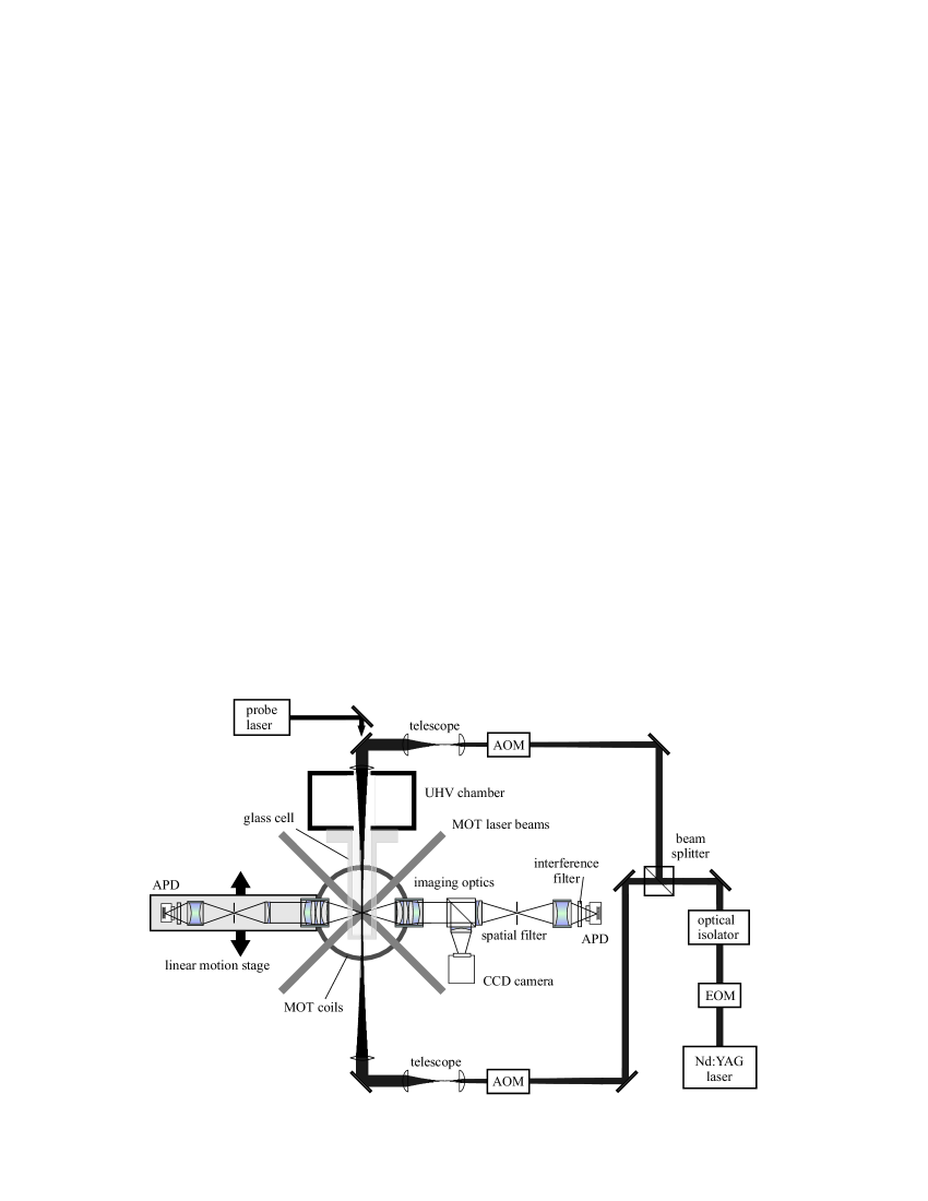
The experimental setup is shown in Fig. 1. Acousto-optical modulators (AOMs) control the frequencies of both laser beams that generate the dipole trap. They are driven by a digital dual-frequency synthesizer (by APE Berlin) with two phase-synchronized RF-outputs. Both AOMs are set up in double-pass configuration in order to avoid beam walk-off during a frequency sweep. To achieve optimal interference contrast of the standing wave, the optical path lengths of both laser beams are equalized. A coherence length of the Nd:YAG laser of cm ensures a fringe visibility close to 100 % within the desired displacement distance.
A standard six-beam magneto-optical trap (MOT) Raab 87 at the center of a UHV glass cell serves as our primary source of single cold atoms Frese 00 . Dissipative forces slow cesium atoms from the background vapor and cool them down to about Doppler temperature. The high magnetic field gradient of 400 Gauss/cm localizes the trapped atoms to a region of diameter 30 m which is much smaller than the 2 mm waist of the MOT lasers. It also provides a low loading rate of 2 atoms/min only which ensures that accidental loading events during the measurement procedure are negligible. We speed up the loading process by temporarily lowering the magnetic field gradient to 40 Gauss/cm. This results in a larger capture cross section which significantly increases the loading rate. After several 100 ms the field gradient is returned to its initial value, concentrating the trapped atoms at the center of the MOT. Varying the time during which the field gradient is low enables us to select a specific mean atom number. This procedure allows us to repeat the experiment with identical parameters in quick succession many hundreds of times. Since we record the initial number of atoms trapped in the MOT, we can evaluate the results for each atom number separately. By slightly increasing the cesium partial pressure in the vacuum chamber this system could easily deliver one atom within 100 ms.
The fluorescence light of the atoms is collected by a diffraction limited objective Alt 01 (NA=0.29) and projected onto an avalanche photodiode (APD, model SPCM-200 by EG&G) with a quantum efficiency of 50 at nm. This yields a photon count rate of per atom. Spatial filtering reduces the MOT laser stray light background to a count rate of , allowing us to determine the exact number of trapped atoms in real time, with a typical uncertainty of in 1 ms. Interference filters transmitting the fluorescence light at 852 nm attenuate the strong Nd:YAG laser stray light to 30 photons/s which is as low as the dark count rates of the APDs.
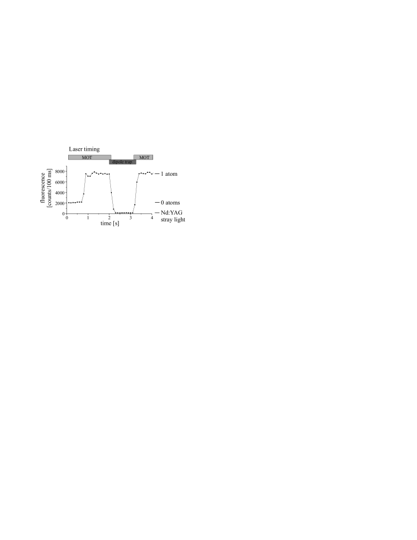
Transfer of atoms from the MOT into the optical dipole trap with a high efficiency is the backbone of the experiment. A prerequisite for efficient transfer is a thorough alignment of the dipole trap laser onto the MOT. As a sensitive alignment criterion we use the fact that the Nd:YAG laser shifts the atomic transition out of resonance, which lowers the fluorescence rate of the MOT. The dipole trap laser is therefore superposed with the MOT by minimizing the fluorescence rate of a single trapped atom Frese 00 . This is done for both dipole trap laser beams separately. Since the localization of the atom in the MOT is tighter than the foci of the two beams, this alignment also yields their optimal mutual superposition to provide the standing wave structure. To transfer cold atoms from the MOT into the dipole trap, both traps are simultaneously operated for several milliseconds before we switch off the MOT (Fig. 2). After storage in the dipole trap the atoms are transferred back into the MOT by the reverse procedure. In other experiments only a fraction of atoms stored in a MOT can be loaded into a dipole trap due to inelastic collisions, see Kuppens 00 and references therein. In our case, however, the small number of atoms together with the perfect superposition of the two small traps and intrinsic cooling during the transfer process Frese 00 warrant a transfer efficiency of nearly 100 .
The ability to transfer atoms between the two traps provides a simple procedure for measuring the lifetime of the atoms in the dipole trap. Background gas collisions limit this trap lifetime to about 25 s. Other heating mechanisms such as photon scattering (about 1.5 K/s in our case), intensity fluctuations and beam pointing instabilities of the trapping laser beams Gehm 98 are not observable in our experiment. However, fluctuations of the relative phase with an rms-value of roughly between the two RF-outputs of the frequency synthesizer are directly translated into position fluctuations of the dipole trap potential. This causes heating of the trapped atoms Alt 01b and limits the lifetime to 3 s, which is still several orders of magnitude longer than all experimentally relevant time scales.
2 Transportation efficiency
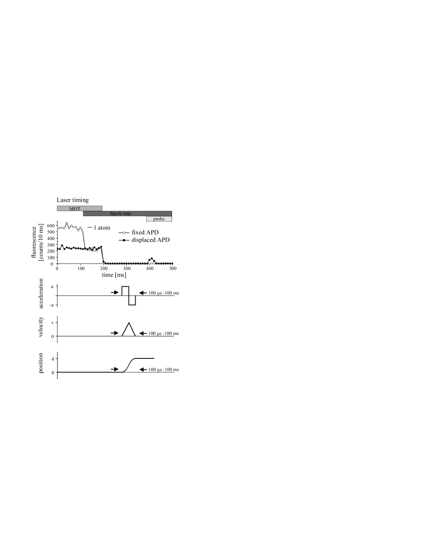
The conveyor belt accelerates a trapped atom and brings it to a stop at preselected points along the standing wave. For this purpose, we transfer one atom from the MOT into the dipole trap (Fig. 3) before the MOT lasers and magnetic field are switched off. To move the atom over the distance it is uniformly accelerated along the first half of and decelerated in the same manner along the second half.
To accomplish this, the digital frequency synthesizer linearly sweeps the frequency of one of the modulators in a phase-continuous way from to and back to (Fig. 3), while the other modulator remains at . Since the AOMs are set up in double pass configuration, the maximum relative detuning of the AOM frequencies is translated into an optical detuning of . These frequency sweeps accelerate and decelerate the standing wave structure achieving a maximum velocity of . The duration of the overall displacement procedure, , determines the required accelerations . The moving potential wells of the dipole trap thus carry the atom along the required distance . This distance can be controlled with sub-micrometer precision by heterodyning both frequencies of the AOM drivers. A counter monitors the number of cycles during a frequency sweep, which directly measures the transportation distance in multiples of .
To observe the atom at its new position, we use a second optical system identical to the one used for collecting fluorescence from the MOT (Fig. 1). Spatial filters limit the field of view to a radius of m, which is much smaller than the typical displacements. A linear motion stage moves both detector and imaging optics by the transportation distance. The fixed imaging optics permanently monitors the MOT region, both to verify the initial presence of a single atom in the MOT and to confirm its absence after displacement, see Fig. 3. At its destination, the transported atom is illuminated by a resonant probe laser ( transition of the D2 line) overlapped with a repumping laser (), providing cyclic optical excitation. Both probe and repumping laser are collimated and overlapped with the Nd:YAG laser and focused to a beam diameter of only 100 m in order to achieve a high intensity of at the position of the atoms without a measurable contribution to stray light. From a single atom we routinely collect 40 fluorescence photons within 40 ms with near zero background. This allows us to unambiguously detect the atom at its new position as long as mm, as will be shown below.
This detection scheme demonstrates the deterministic delivery of a single atom to a desired position. The measured probability to observe the transported atom as a function of the displacement is shown in Fig. 4 as empty circles. For small distances, the fraction of detected atoms is above 90 %. However, the position dependence of the trap depth limits this detection efficiency for larger displacements from the laser focus. The tight focusing of the trapping laser beams yields a Rayleigh length of only 3 mm. Due to the divergence of the beams, the local trap depth scales with the displacement from the focus as
| (4) |
During resonant excitation the atom is heated by scattering photons. The fluorescence signal lasts until the atom is evaporated out of the trap, which happens on average after scattering events. Here is the photon recoil energy with . As a consequence, we observe that the number of detected fluorescence photons per atom is proportional to . In this measurement we detect the presence of the atom if a fluorescence peak substantially exceeds (more than 5 photons) the stray light background (2 photons on average) of the Nd:YAG and the probe laser beams. Thus, at mm, the probe laser can evaporate the atom out of the dipole trap before enough fluorescence photons have been detected.
The actual transportation efficiency, however, is much higher than that shown by the resonant illumination detection. To demonstrate this, we use the MOT to detect the atom with 100 % efficiency. Without resonant illumination, the displaced atom is transported back to before we switch on the MOT lasers to reveal the presence or absence of the atom. The results of this measurement are shown in Fig. 4 as filled circles. Even for distances as large as 10 mm, the two-way transportation efficiency remains above 80 %. At a distance of 15 mm, however, the transportation efficiency drastically decreases to 16 .
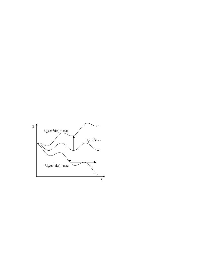
The atoms are lost at this distance because gravity reduces the effective potential depth. In our setup, the optical -axis of the dipole trap is oriented horizontally. Thus, the potential in vertical direction is the sum of the radial dipole trapping potential and the gravitational potential
| (5) |
where is the trap depth of a potential well, given in Eq. (4). The acceleration due to gravity tilts these Gaussian potential wells, which reduces the trap depth to , see Fig. 5. In contrast to the pure Lorentzian dipole potential , this effective potential disappears at mm. However, due to the initial energy of the atom, we lose the atom at even smaller distances. This interpretation is supported by an independent measurement Alt 01b in a stationary standing wave. We measured the survival probability of the atom after an adiabatic lowering of the trap depth by attempting to recapture it in the MOT. We observed that 80 of the atoms survive if the trap depth is reduced from to , which equals the effective potential depth at mm. However, a reduction to , which corresponds to a displacement to mm, yielded a survival probability of only 10 . This is in agreement with the measured transportation efficiency of 16 % at mm.
More complicated position manipulations than a simple displacement of an atom along the standing wave are possible. We implemented an ’atomic shuttle’ by transporting one atom by 1 mm and then reversing the direction of motion repeatedly. After swapping the atom back and forth times, it is directly detected using resonant illumination (Fig. 6). Each acceleration process causes heating of the atom as discussed below which results in a decreased detection efficiency. Heating processes are sufficiently small, such that a single atom bounces back and forth 30 times with a measured efficiency of 40 %.
3 Acceleration
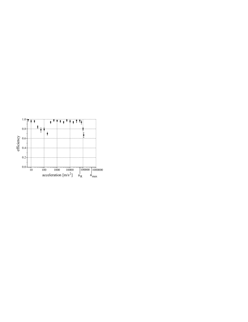
We have investigated the transportation efficiency as a function of the acceleration for a constant displacement of 1 mm using resonant illumination detection. Although the acceleration was varied over 4 orders of magnitude (Fig. 7), we found a nearly constant transportation efficiency of more than 90 % for m/s2. For larger accelerations, the efficiency rapidly decreases.
The potential in the accelerated frame is the sum of the periodic potential of the standing wave and the contribution of the accelerating force, . In the ideal case of an initially motionless atom, the acceleration could be adiabatically increased until the local minima of the standing wave disappear. The acceleration is thus fundamentally limited by the potential depth, m/s2.
However, there are two effects that experimentally limit the maximum acceleration to a lower value. The first is an additional heating effect due to abrupt changes of the acceleration. At the beginning of the transportation process the acceleration is instantly switched from 0 to and similarly from to after half the transportation distance (Fig. 3). The equilibrium position of the accelerated potential is shifted by the amount (Fig. 8). These sudden changes of the potential, which occur three times during a transportation process, either heat or cool the atom depending on the phase of its oscillation. The atom can increase its energy twice during the first two changes, as illustrated in Fig. 8 where the worst case of a maximal energy gain is shown. This leads to a non-zero probability to lose the atom for accelerations exceeding . The initial thermal energy of the atom, corresponding to in our case Alt 01b , reduces this value to . For accelerations below this heating effect can be neglected. The maximum energy gained due to abrupt jumps of the acceleration for is so that is only K. Changing the acceleration slowly enough would avoid this heating effect completely because the atom would then adiabatically follow the motion of the potential well.
The second fact that experimentally limits the maximum acceleration is the finite bandwidth of the AOMs. The highest acceleration achieved requires a mutual detuning of up to MHz of the counter-propagating laser beams. For these parameters, the AOM deflection efficiency decreases by 50 which results in a similar decrease of the dipole trap laser power and thus of the trap depth. Due to the combination of these two effects the transportation efficiency should decrease for accelerations exceeding m/s2. This is indeed what we observe. Note, however, that the accelerations realized here still exceed that of the maximum resonant light pressure force, m/s2. Here, is the photon momentum. This allows us to change the atomic velocity from zero to the maximum velocity of 10 m/s (limited by the AOM bandwidth) within 100 s.
The decrease of the transportation efficiency around 100 m/s2 is attributed to a modulation of the dipole trap potential caused by partial reflection of one of the laser beams on the glass cell. The reflected beam interferes with the standing wave which is thus phase and amplitude modulated. For appropriate detunings this effect causes either resonant or parametric heating of the atoms. This mechanism can be used to measure the oscillation frequency of the atoms in the trap and is currently under study Alt 01b . If required, the effect could be avoided by slightly changing the geometry of the setup or by selecting proper detunings of the two beams.
4 Conclusions and outlook
We have realized a deterministic source of cold atoms which delivers a prescribed number of single atoms to a desired spot. The precise control of the experimental parameters allows us to transport a single atom over the distance of 10 mm within 1 ms with an accuracy of . The absolute position of the atom is limited by the size of the MOT. The decrease in the efficiency at larger distances is accredited only to the effect of gravity. This indicates that larger displacements could be achieved by using higher laser power and different beam geometries. Moreover, additional cooling of the trapped atoms would further improve the performance of the atomic conveyor-belt.
Alternative approaches are possible to control the motion of the standing wave interference pattern. The first is to retro-reflect one of the trap laser beams by a mirror. Translating the mirror would result in a travelling wave. This mechanical solution would avoid the major heating effect due to the phase noise of the AOM drivers. Its disadvantages, however, are a worse overall stability and much lower possible accelerations and velocities. A second alternative is to use an EOM to phase-shift one of the laser beams. Here, an adiabatic shift from 0 to moves the interference pattern along with the trapped atom by . Then, the EOM rapidly switches the phase from back to 0 without the atom being able to follow. Repeating this procedure times transports the atom over the distance of . This approach would simplify the optical setup at the cost of placing demanding requirements on the EOM driver.
One of the most interesting applications of the optical conveyor-belt is the controlled positioning of two or more atoms in the fundamental mode of a high-finesse optical cavity. In current single-atom cavity-QED experiments Hood 00 ; Pinkse 00 atoms are released from a MOT and thus enter the cavity in a random way. Our device, however, could place a predetermined number of atoms into the cavity deterministically. This could provide the possibility to entangle neutral atoms via the exchange of optical photons Pellizzari 95 ; Beige 00 , a demanding task which, so far, has only been accomplished in the microwave domain Hagley 97 ; Rauschenbeutel 00 .
Acknowledgements.
We have received support from the Deutsche Forschungsgemeinschaft and the state of Nordrhein-Westfalen.References
- (1) W. Neuhauser, M. Hohenstatt, P.E. Toschek, H. Dehmelt: Phys. Rev. A 22, 1137 (1980)
- (2) C. Roos, T. Zeiger, H. Rhode, H.C. Nägerl, J. Eschner, D. Leibfried, F. Schmidt-Kaler, R. Blatt: Phys. Rev. Lett. 83, 4713 (1999)
- (3) C.A. Sackett, D. Kielpinski, B.E. King, C. Langer, V. Meyer, C.J. Myatt, M. Rowe, Q.A. Turchette, W.M. Itano, D.J. Wineland, C. Monroe: Nature 404, 256 (2000)
- (4) S. Chu, J.E. Bjorkholm, A. Ashkin, A. Cable: Phys. Rev. Lett. 57, 314 (1986)
- (5) N. Davidson, H. Jin Lee, C.S. Adams, M. Kasevich, S. Chu: Phys. Rev. Lett. 74, 1311 (1995)
- (6) R. Grimm, M. Weidemüller, Y.B. Ovchinnikov: Adv. At. Mol. Opt. Phys. 42, 95 (2000)
- (7) S. Kuhr, W. Alt, D. Schrader, M. Müller, V. Gomer, D. Meschede: Science XXX, YYYY (2001), Published online June 14 2001; 10.1126/science.1062725
- (8) M. Ben Dahan, E. Peik, J. Reichel, Y. Castin, C. Salomon: Phys. Rev. Lett. 76, 4508 (1996)
- (9) S.R. Wilkinson, C.F. Bharucha, K.W. Madison, Q. Niu, M.G. Raizen: Phys. Rev. Lett. 76, 4512 (1996)
- (10) W. Hänsel, J. Reichel, P. Hommelhoff, T.W. Hänsch: Phys. Rev. Lett. 86, 608 (2001)
- (11) D. Frese, B. Ueberholz, S. Kuhr, W. Alt, D. Schrader, V. Gomer, D. Meschede: Phys. Rev. Lett. 85, 3777 (2000)
- (12) N. Schlosser, G. Reymond, I. Protsenko, P. Grangier: Nature 411, 1024 (2001)
- (13) W. Alt, S. Kuhr, D. Schrader, M. Müller, V. Gomer, D. Meschede: in preparation
- (14) E.L. Raab, M. Prentiss, A. Cable, S. Chu, D.E. Pritchard: Phys. Rev. Lett. 59, 2631 (1987)
- (15) W. Alt: submitted to Rev. Sci. Instr. (2001)
- (16) S.J.M. Kuppens, K.L. Corwin, K.W. Miller, T.E. Chupp, C.E. Wieman: Phys. Rev. A 62, 013406 (2000)
- (17) M.E. Gehm, K.M. O’Hara, T.A. Savard, J.E. Thomas: Phys. Rev. A 58, 3914 (1998); T.A. Savard, K.M. O’Hara, J.E. Thomas: Phys. Rev. A 56, R1095 (1997)
- (18) C.J. Hood, T.W. Lynn, A.C. Doherty, A.S. Parkins, H.J. Kimble: Science 287, 1447 (2000)
- (19) P.W.H. Pinkse, T. Fischer, P. Maunz, G. Rempe: Nature 404, 365 (2000)
- (20) T. Pellizzari, S.A. Gardiner, J.I. Cirac, P. Zoller: Phys. Rev. Lett. 75, 3788 (1995)
- (21) A. Beige, D. Braun, B. Tregenna, P.L. Knight: Phys. Rev. Lett. 85, 1762 (2000)
- (22) E. Hagley, X. Maître, G. Nogues, C. Wunderlich, M. Brune, J.M. Raimond, S. Haroche: Phys. Rev. Lett. 79, 1 (1997)
- (23) A. Rauschenbeutel, G. Nogues, S. Osnaghi, P. Bertet, M. Brune, S. Haroche: Science 288, 2024 (2000)
Figures