Full mechanical characterization of a cold damped mirror
Abstract
We describe an experiment in which we have used a cold damping feedback
mechanism to reduce the thermal noise of a mirror around its mechanical
resonance frequency. The monitoring of the brownian motion of the mirror
allows to apply an additional viscous force without any thermal fluctuations
associated. This scheme has been experimentally implemented with the
radiation pressure of an intensity-modulated laser beam. Large noise
reductions, up to 30 dB, have been obtained. We have also checked the
mechanical response of the cold damped mirror, and monitored its transient
evolution between the cooled regime and the room temperature equilibrium. A
simple theoretical model allows to fully explain the experimental results. A
possible application to the active cooling of the violin modes in a
gravitational-wave interferometer is discussed.
PACS : 05.40.Jc, 04.80.Nn, 42.50.Lc
I Introduction
Thermal noise is a major limitation to many very sensitive optical measurements such as interferometric gravitational wave detection[1, 2]. The suspended mirrors of interferometric detectors have many degrees of freedom: pendulum modes of the suspension system (with resonance frequencies below the analysis band), violin modes of the suspension wires (with some resonances within the detection band), and mirrors’ internal acoustic modes (with resonance frequencies above the band)[3]. The thermal motion of each degree of freedom results from its excitation by a thermal random force, called the Langevin force. The fluctuation-dissipation theorem relates the spectrum of the Langevin force to the temperature and to the mechanical damping of the mode. Up to now, only passive methods such as the increase of mechanical quality factors[4] or cryogenic methods to lower the temperature[5] have been considered to lower the thermal noise and increase the sensitivity.
It has been recently proposed to use a feedback loop to reduce the thermal noise of a mirror in a high-finesse optical cavity [6]. A Fabry-Perot cavity is actually a very sensitive displacement sensor [7] and a feedback mechanism can be used to control the brownian motion of a mirror, for example via the radiation pressure of an intensity-modulated laser beam [8]. This approach allows to reduce the thermal noise both at the mechanical resonance frequencies of the mirror and at low frequency. At resonance, this cooling corresponds to a cold damping mechanism, the radiation pressure of the light applying a viscous force to the mirror without any additional thermal noise.
The purpose of this paper is to present a more detailed theoretical analysis of the experiment described in[8], focussing on the resonant case, and to present new experimental results on the mechanical response of the cold damped mirror and on the transient behavior of the system.
Section II is dedicated to a brief reminder of the fluctuation-dissipation theorem and its consequences on the thermal noise spectrum. Section III presents a detailed theoretical analysis of the cold damping process used in section IV to lower the effective temperature of the fundamental acoustic mode of a mirror. In section V we take into account the background thermal noise due to the other acoustic modes of the mirror to explain the discrepancy between experimental results and the simple monomode theory of section III.
We present in section VI the full mechanical characterization of the cold damped mirror. We have studied the mechanical response of the mirror to an external force, when the cooling is applied. The results show that the mechanical susceptibility is changed in agreement with a cold damping mechanism: the additional radiation pressure corresponds to a viscous force and there is no additional noise associated with this force, except the electronic noise of the feedback loop.
Finally, we present the transient evolution of the thermal noise when the cold damping is switched on or off (section VII). The results show that the relaxation time towards the cooled regime can be much shorter than the relaxation time towards the thermal equilibrium. These transient characteristics may be used to perform a cyclic cooling of the thermal noise associated with the violin modes of the mirrors in a gravitational-wave interferometer.
II Thermal noise and fluctuation-dissipation theorem
We present here some well known results on thermal noise and on the fluctuation-dissipation theorem, which will give some physical insight to the efficiency of the feedback scheme used to lower the temperature.
Each degree of freedom is equivalent to a harmonic oscillator, whose thermal motion is the consequence of the thermal energy and appears as the mechanical response of the oscillator to a Langevin force describing the coupling to a thermal bath. In the framework of linear response theory [9], the resulting motion can be described by its Fourier transform at frequency which is proportional to ,
| (1) |
where is the mechanical susceptibility of the mode,
| (2) |
with a mass , a resonance frequency , and a loss angle . In the following, we consider only the case of a viscous damping, e.g.:
| (3) |
where is the mechanical damping of the mode. It is well known that such a loss angle may not be appropriate to describe some degrees of freedom, such as internal acoustic modes of the mirrors[10]: is usually considered as independent of frequency over a large frequency range. However, as we are only interested in the spectral analysis of the motion at frequencies close to a mechanical resonance, for low loss oscillators (), both descriptions are equivalent. The former, leading to a simple physical interpretation, will be used throughout the paper.
The spectrum of the Langevin force is related by the fluctuation-dissipation theorem[9] to the mechanical susceptibility,
| (4) |
According to Eqs. (1) to (4), the noise spectrum of the displacement at temperature has a lorentzian shape,
| (5) | |||||
| (6) |
Performing the integration of (6) over frequency yields the thermal variance , which obeys the equipartition theorem,
| (7) |
If we see the thermal motion as a response to the Langevin force , it should be clear that increasing the damping would reduce the thermal variance. However the damping cancels from that expression, because it appears both in the mechanical susceptibility and in the spectrum of the Langevin force. Decreasing the damping however concentrates the thermal noise around the mechanical resonance frequency, and therefore lowers both the low frequency and high frequency thermal noises, which is the reason for the ongoing works on low loss materials for the substrates of the mirrors and the suspension wires [4].
The total noise spectrum, taking into account all the mechanical modes, is the sum of such lorentzian components. Near one of the mechanical resonances, the thermal noise is mainly ruled by the resonant component, with a background noise related to all other modes and approximately flat in frequency.
III Cold damping theory
The cooling mechanism is based on a measurement of the thermal noise of the mirror and on a feedback loop which applies a properly adjusted force on the mirror. We will see in section IV a practical implementation of such a mechanism. Let us only assume here that we are able to measure the position of the mirror, and to apply a viscous feedback force , proportional to the speed of the mirror,
| (8) |
where is a dimensionless parameter related to the gain of the feedback loop. In this section we assume that the mirror can be described as a single harmonic oscillator. The resulting motion is given by
| (9) |
where is the mechanical susceptibility (2) with a loss angle of the form (3), and is the Langevin force whose spectrum is given by the fluctuation-dissipation theorem (4). The motion can be written as
| (10) |
where is an effective mechanical susceptibility given by
| (11) |
The additional viscous force (8) has obviously increased the damping, but, unlike the case of passive damping, the Langevin force is not modified and still verifies the fluctuation-dissipation theorem (4): it is only related to the natural damping of the oscillator. We will see shortly that this so called cold damping mechanism[11, 12] allows to reduce the effective temperature of the system.
Equations (10) and (11) show that the mirror now responds to the Langevin force with the effective mechanical susceptibility . As the spectrum of is flat against frequency, the thermal noise spectrum in presence of feedback still has a lorentzian shape, of width ,
| (12) |
As the random force has not been increased, the variance of the motion is reduced. Performing the integration of (12) over the frequency yields
| (13) |
The cold damped oscillator of damping and at thermodynamical temperature is therefore equivalent to an oscillator with an effective damping
| (14) |
at an effective temperature
| (15) |
This can also be deduced from the spectrum of the Langevin force which can be written as
| (16) |
where both and have already been defined. The increase of the effective damping therefore decreases the effective temperature of the oscillator. The cold damped mirror is still at thermodynamical equilibrium but, unlike the case of passive damping, the temperature is reduced.
We can also define the amplitude noise reduction
| (17) |
Off resonance, goes to unity: as the mechanical susceptibility gets real, the change of its imaginary part does not contribute anymore to a modification of the spectrum . The amplitude noise reduction is maximum at resonance where it is equal to
| (18) |
We have shown in this section that measuring the position of an oscillator allows the realization of a feedback loop to apply an additional viscous force to the oscillator without any additional thermal fluctuations. Such a cold damping scheme allows to set the oscillator at thermal equilibrium at a lower temperature. This is the case only for a single harmonic oscillator. We will see in section V that there is no longer a thermodynamical equilibrium when one takes into account all the acoustic modes.
IV Observation of the cold damping
In this section, we present the experimental implementation of the feedback scheme presented in the previous section. The oscillator is the fundamental acoustic mode of a plano-convex resonator. We present the experimental results on the cooling at resonance, and the dependence of the effective damping and temperature with the gain of the feedback loop.
A Presentation of the oscillator and motion sensor
The oscillator used throughout the paper is the fundamental acoustic mode of a mirror coated on the plane side of a plano-convex resonator made of fused silica, whose thermal noise observation has been reported in[7]. The mirror has a thickness (at the center) of , a diameter of , and a curvature radius of the convex side of . With the value of sound velocity in silica, the value of the thickness yields a fundamental resonance a bit below

The mirror has been coated at the Institut de Physique Nucléaire de Lyon and is used as the end mirror of a single-port high-finesse optical cavity (figure 1). The coupling mirror is a Newport high-finesse SuperMirror, held at of the rear mirror. The light entering the cavity is provided by a titane-sapphire laser working at and frequency locked to an optical resonance of the high-finesse cavity. The light beam is also intensity-stabilized and spatially filtered by a mode cleaner.
The phase of the field reflected by the cavity is very sensitive to changes in the cavity length. It is monitored by a homodyne detection. The signal is superimposed to the quantum phase noise of the reflected beam. With our parameters (finesse of the cavity , wavelength of the light and incident power ), the quantum limited sensitivity is on the order of [7]. The quantum noise is therefore negligible and the phase of the reflected field reproduces the brownian motion of the mirror.
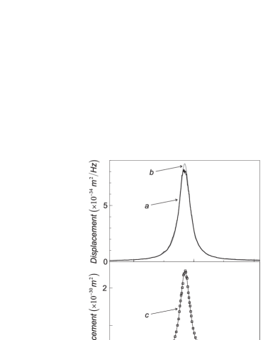
Curve (a) of figure 2 shows the phase noise spectrum of the reflected field for frequencies around the fundamental resonance frequency of the mirror. The noise is calibrated in displacements of the mirror and reflects the brownian motion of the mirror which is peaked around the resonance frequency. This experimental result allows to deduce the mechanical resonance frequency of the fundamental acoustic mode of the resonator:
| (19) |
The mechanical susceptibility has a lorentzian shape with a width
| (20) |
In other words, the mechanical quality factor has a value of which seems to be limited by clamping losses. The effective mass of the mode is deduced from the equipartition theorem,
| (21) |
B Implementation of the feedback loop
To apply a controlled force on the mirror, we use an auxiliary laser beam reflected from the back on the mirror (see figure 1). This beam is derived from the same laser source as the one used for motion sensing. The beam is intensity-modulated by an acousto-optic modulator so that a modulated radiation pressure is applied to the mirror:
| (22) |
where is the wave vector of the laser and is the intensity modulation, expressed as the number of photons per second. therefore appears as the momentum transferred to the mirror during the reflection of a single photon, multiplied by the number of reflections per second.
Driving the acousto-optic modulator with a monochromatic excitation then allows to characterize the dynamics of the mirror at that frequency. We scan the excitation frequency for values spanned around the resonance frequency in order to characterize the mechanical response of the mirror to an external force, as this has been done in[7]. The mechanical response shown in curve (2c) displays a resonance centered on the same frequency as the thermal noise, and with the same width. Moreover, the observed thermal noise spectrum is in excellent agreement with the spectrum deduced from this mechanical response and the fluctuation-dissipation theorem (curve 2b) [7]. This confirms that the observed thermal peak is related to the brownian motion of the fundamental acoustic mode of the plano-convex resonator at room temperature.
Note that the optical excitation is very efficient: with an approximately completely modulated auxiliary beam, one gets a displacement at resonance larger than the one associated with the thermal noise for a resolution bandwidth of the spectrum analyzer.
This setup can be used to implement the feedback loop discussed in section III. Indeed, the signal given by the homodyne detection is proportional to the displacement of the mirror:
| (23) |
where the factor depends on the analysis frequency through the filtering by the cavity. In the following, we will focus on the thermal noise spectrum on a band around the fundamental resonance frequency. This band is small compared to the bandwidth of the cavity (on the order of ), so that can be considered constant. Moreover, this band is small compared to the mechanical resonance frequency , so that can also be considered constant and the derivation necessary to obtain the force (8) from the displacement can be practically obtained by a dephasing of the homodyne signal. The feedback loop is therefore simply made of an amplifier with adjustable gain and phase, in order to drive the acousto-optic modulator with a signal in quadrature with the displacement .
The signal is also filtered by an electronic bandpass filter inserted in the loop in order to avoid the saturation of the feedback. Indeed, the homodyne signal also comprises resonances associated with higher order modes of the plano-convex resonator (at higher frequencies) and resonances of the input mirror (mainly at lower frequencies). Moreover, even for the fundamental acoustic mode considered here, the spectrum of the Langevin force is flat against frequency and may lead to the saturation of the loop.
As we are only interested in the spectrum around the mechanical resonance frequency, the filter is centered on this frequency. Its bandwidth is chosen large enough in order to limit its effect on the frequency band of around the resonance, and small enough in order to efficiently filter the low-frequency and high-frequency tails of the resonance. The results presented here have been obtained with a bandwidth, which fulfills both conditions. The influence of the filter can therefore be neglected in our theoretical model.
C Noise reduction at resonance
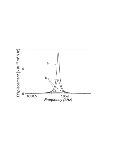
Figure 3 presents the thermal noise spectra obtained without feedback, and with feedback for increasing values of the gain of the loop [8]. The thermal noise at the mechanical resonance frequency is strongly reduced. Meanwhile, as predicted by our theoretical model, the width of the resonance is strongly increased. The effective temperature of the oscillator is related to the variance and thus to the area of the curve. The decrease of these areas thus corresponds to a cooling of the mirror. We will see in the following that large cooling factors can be obtained.
D Dependance of the cooling with the gain
In order to check our theoretical model, it is instructive to study the efficiency of the cooling mechanism with respect to the gain of the feedback loop. To measure the feedback gain, we detect the intensity of the auxiliary beam after its reflection on the mirror. According to Eq. (8), the ratio between the modulation spectrum of the intensity at frequency and the noise spectrum of the displacement leads to the gain , a multiplicative factor aside. Such a measurement takes into account any nonlinearity of the gain due to a possible saturation of the acousto-optic modulator.
Figure 4 shows the relative damping and the amplitude noise reduction at resonance experimentally observed. These parameters are derived from the experimental spectra by lorentzian fits. As expected from Eqs. (14) and (18), both have a linear dependence with the gain. The straight line in figure 4 is in excellent agreement with experimental data, and allows to normalize the gain , as this has been done in the figure. However, the cooling factor , derived from the area of the lorentzian fit, does not obey the linear dependence (15). The following section is dedicated to the explanation of this behavior.
V Influence of the background thermal noise
The purpose of this section is to derive a more sophisticated theory of our experiment, in order to explain the nonlinear dependence of the effective temperature with the gain of the loop. This dependence is due to the background thermal noise associated with other acoustic modes of the mirror or with the input mirror of the cavity.
A Dependence of the temperature with the gain
We can take this background noise into account in our theoretical model. Suppose we note the associated Fourier component, and its noise spectrum. As there is no acoustic resonance around the frequency band of interest, is supposed to be frequency independent. The noise is uncorrelated to the Langevin force of the fundamental mode, and the overall noise spectrum without feedback is the sum of the resonant and background components,
| (24) |
where is the noise spectrum of the fundamental mode (Eq. 6).
Moreover, as the feedback does not involve the input mirror, and as we have already seen that the efficiency of the loop strongly decreases off resonance, we can state that the background thermal noise is unaffected by the loop. We then have
| (25) |
where is the mechanical susceptibility of the fundamental acoustic mode and the radiation pressure is related to the overall displacement by Eq. (8). The resulting motion is
| (26) |
where is the effective susceptibility of the fundamental mode given by Eq. (11). As and are uncorrelated, the noise spectrum takes the simple form:
| (27) |
where is the lorentzian spectrum obtained when neglecting the background noise (Eq. 12), and is the amplitude noise reduction defined in Eq. (17). Combining Eqs. (17) and (27) leads to
| (28) |
The feedback loop still decreases the noise spectrum by a factor . In other words, the effect of the feedback is unchanged since it is still described by the mechanical susceptibilities and of the fundamental mode only, but the background noise in leads to a background noise evenly modified in . The noise spectrum (27) can also be written as
| (29) |
where is the ratio between the background noise spectrum and the resonant component at frequency of the thermal noise without feedback (Eq. 24). The overall noise spectrum stays lorentzian, the area of the lorentzian component being smaller when taking into account, with an unchanged background noise.
The width of the resonance is still equal to , and the overall amplitude noise reduction is unchanged and equal to as we have experimentally observed in figure 4.
The effective temperature of the fundamental acoustic mode, related to the area of the resonant component of the spectrum by the equipartition theorem, can be computed using Eq. (29):
| (30) |
The background thermal noise () thus decreases the effective temperature.
One can experimentally obtain the ratio using the lorentzian fit of the thermal noise spectrum observed without feedback (figure 2a). The experimental value is The solid curve in figure 4 is a fit of the experimental points using Eq. (30). The optimum value is , close to the expected value. The theoretical curve is in excellent agreement with the experimental points: taking the background thermal noise into account thus allows to explain the dependence of the effective temperature with the gain of the feedback loop.
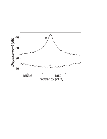
The effective temperature defined previously holds for the resonant mode, but as the background is unchanged by the feedback loop, one can say that all the other acoustic modes stay at room temperature . The mirror is thus no longer in a thermodynamical equilibrium. For sufficient large gains ( in our experiment), the feedback loop can dig a hole in the background noise, leading to a negative effective temperature for the resonant mode. Figure 5 shows the thermal noise spectrum experimentally observed for . This figure also shows that very significant noise reduction can be obtained: the noise power is reduced at resonance by a factor larger than .
B Background noise and thermal equilibrium
We have discussed in the previous section how the background thermal noise alters the cooling mechanism. We have used a phenomenological model, where the background thermal noise is described as an additional noise which is unaffected by the feedback loop. If we neglect the contribution of the coupling mirror to the background noise, it is possible to derive the same result more formally.
One can show that the motion of the mirror as seen by the intracavity light can be described by an effective mechanical susceptibility which takes into account all the acoustic modes and their spatial overlap with the laser beams [13]:
| (31) |
where is the mechanical susceptibility of the acoustic mode with spatial deformation along the axis of the cavity at every point of the surface, is the spatial profile of the intensity for the intracavity field and for the cooling beam (we assume that both beams have the same profile). here stands for the spatial overlap between two two-dimensional functions,
| (32) |
The thermal motion is then described by an effective Langevin force, which is a sum of the Langevin forces associated with each acoustic mode. One can show [13] that this Langevin force obeys the fluctuation-dissipation theorem with respect to , and the thermal noise spectrum is therefore given by
| (33) |
Around any resonance of the mirror, most of the dynamics is ruled by the resonant mode, and mostly displays the resonant behavior of this mode.
We can now compute the motion of the mirror with the feedback. The motion is as previously
| (34) |
where is the mechanical susceptibility of the cold damped mirror,
| (35) |
Using Eqs. (33) and (34), the displacement noise spectrum takes the form:
| (36) | |||||
| (37) |
As a first approximation, one can replace the effective susceptibility around the fundamental resonance of the mirror by its resonant component, and find the thermal noise spectrum in presence of feedback:
| (38) |
where has already been defined (see Eq. 17). As previously, we find that the overall thermal noise spectrum is reduced by a factor . The corrections involved by the off resonance terms in are negligible for our experimental conditions: the existence of all other acoustic modes leads to the presence of a background thermal noise in the noise spectra and , but the dynamics of the cooling mechanism is mainly described by the resonant component of
This model also allows to show that the mirror is no longer in thermodynamical equilibrium in presence of feedback. Indeed, this would require to be able to define an effective temperature obeying the fluctuation-dissipation theorem at every frequency :
| (39) |
Using Eqs. (35) and (39), one can show that this requires:
| (40) |
This condition can be fulfilled only if depends linearly of the frequency . This is the case if describes the mechanical response of a single harmonic viscously-damped oscillator, but it is no longer the case for a mechanical resonator with many acoustic modes.
VI Mechanical response of the cold damped mirror
The experimental results presented in section IV have shown that it is possible to reduce the observed thermal noise at resonance by a factor with the feedback loop. However the observed quantity is the dephasing of the reflected field, which drives the feedback loop. This error signal goes to zero as the gain of the loop is increased. In other words, the fact that the thermal noise is reduced does not prove that the feedback corresponds to a cold damping mechanism. To check if the residual brownian motion of the mirror is given by Eqs. (10) and (11) (or Eqs. 34 and 35 in presence of a background thermal noise), we can determine the cold damped mechanical susceptibility by measuring the mechanical response of the mirror to an external force. This, combined with the observation of the brownian motion, allows to check that the Langevin force is not altered by the feedback loop, and that the residual brownian motion is given by Eq. (10).
A Response to an external force
The motion of the mirror under the combined influence of the Langevin thermal force , the cold damping force , and the external force used to measure its mechanical susceptibility is
| (41) | |||||
| (42) |
where the effective mechanical susceptibility has been defined in Eq. (35). In presence of feedback, the mirror responds the same way to the Langevin force and to an external force. Checking the mechanical response, one must observe a widening and an amplitude decrease as the gain of the loop is increased.
B Experimental results
The cold damped mechanical susceptibility is measured by the same technique already used in [7]. We use a second auxiliary beam, which is intensity-modulated by an independent acousto-optic modulator controlled by a high-frequency oscillator. The two auxiliary beams are mixed by a polarizing beamsplitter before their reflexion on the mirror. The intensity of the second beam is , corresponding to a displacement at resonance with respect to the thermal noise level. It is lower than the one of the cooling beam (, ) in order not to alter the cooling mechanism.
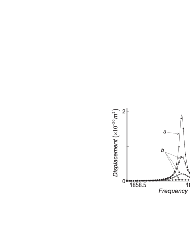
For each value of the gain of the loop, we measure the thermal noise spectrum, which is used to calibrate . We then proceed to a characterization of the response of the mirror to the external force in presence of feedback. The response is measured for values of the modulation frequency of the second auxiliary beam, spanned around the mechanical resonance. Figure 6 represents the modulation power measured for different values of the gain of the loop. Note the similarity between this figure and figure 3.
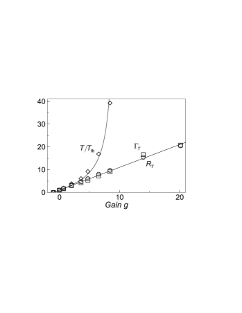
Each of the curves of figures 3 and 6 can be compared to a lorentzian fit, taking into account the presence of a background thermal noise. One gets the relative width of the thermal resonance, the relative width of the modulation resonance, the amplitude thermal noise reduction at resonance (defined in Eq. 18), and the amplitude modulation reduction at resonance obtained from the ratio between curves (b) and (a) of figure 6. Figure 7 represents the dependence of these parameters as a function of the gain of the loop ( is not displayed for because the width of the noise spectrum is then too large to be accurately measured with a acquisition bandwidth).
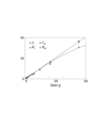
For , the experimental points are well aligned on a unity slope straight line. This confirms that the parameters obey the expected linear dependence. The susceptibility perfectly describes the mechanical behavior of the cold damped mirror. Moreover, the thermal noise spectrum, characterized by and , still obeys the fluctuation-dissipation theorem with the mechanical susceptibility . As stated in our theoretical model, the Langevin force is not altered by the cooling mechanism.
C Influence of the electronic noise of the loop
However, for sufficient large gains, the measured thermal noise reduction is lower than expected with our theoretical model. This is due to the electronic noise of the feedback loop. We can take this noise into account in our model. Suppose we note the electronic noise of the loop. The cold damping force then takes the form
| (43) |
and the resulting motion is
| (44) |
The response to an external force is not altered by the electronic noise, and it is still described by the effective susceptibility . However, the observed noise without any external force does depend on the electronic noise . As the electronic noise is uncorrelated to the Langevin force, and flat in frequency on the frequency band of interest, the thermal noise spectrum appears as the sum of the thermal noise in presence of feedback (see Eq. 38) and the electronic noise spectrum injected by the feedback loop,
| (45) |
The thermal noise spectrum therefore still has a lorentzian shape of width , as it is proportional to but its amplitude does depend on the electronic noise. The thermal noise at the mechanical resonance frequency is
| (46) |
The influence of the electronic noise therefore increases with the gain of the loop. The amplitude noise reduction at resonance is now
| (47) |
The electronic noise can be experimentally measured from the characteristics of the amplifier used in the loop, and one gets . The solid curve in figure 7 shows the expected dependence of with the gain, without any adjustable parameter. It is in excellent agreement with experimental data.
VII Transient regime
We have focussed up to now on the steady-state of the cold damped mirror. Some questions however arise. What is the timescale of the transition from the natural regime (at thermodynamical temperature ) to the cold damped regime (at effective temperature )? And when the cooling mechanism is switched off? It is well known that the quality factor (and therefore the damping ) can be measured through the decay time of a mechanical excitation abruptly switched off. Is it still true for the cold damped regime? In this section, we present the measurements of the timescale needed for the mirror to reach its equilibrium state, first when the cooling is applied or switched off abruptly, and then in the case of a mechanical excitation, both for the open-loop and the cold damped cases.
A Transition to and from a damped regime
Suppose we apply sharply the cooling mechanism at . For , the equation of motion is
| (48) |
where is the temporal evolution of the Langevin force. The last term of Eq. (48) represents the cold damping force. One has to solve this equation with initial conditions related to the previous thermodynamical equilibrium at temperature . The effect of the cooling mechanism can be monitored on the variance , which is directly related to the effective temperature by the equipartition theorem. We show in Appendix A that the time evolution of the variance is given by
| (49) |
where is the thermal variance without feedback. The temperature therefore decreases to its new equilibrium value with a time constant . In other words, the mirror evolves towards its damped regime with a mechanical response corresponding to its effective susceptibility in presence of feedback.
In the opposite case, when the cooling is abruptly switched off, the variance obeys (see Appendix A):
| (50) |
The variance goes back to its thermal equilibrium value with a time constant which is now related to the mechanical damping without feedback. The transient evolution to the cooled regime is then faster by a factor than the relaxation towards the thermal equilibrium.
To observe these transient regimes, the evolution of the variance is monitored with the spectrum analyzer, centered on the resonance frequency in the zero-span mode. A fast electronic switch is inserted in the loop in order to switch alternatively the loop on and off. We have checked that the transition time of the switch is negligible as compared to the mechanical time-scales.
The resolution bandwidth of the analyzer must be large enough in order to reduce the temporal filtering caused by the spectrum analyzer, but not too large compared to the width of the mechanical resonance, so that the background noise does not contribute too much to the observed signal. With a bandwidth of , both conditions are fulfilled, the time constant of the analyzer being on the order of .

Figure 8 shows the evolution of the variance. When the cooling is applied, the variance decreases with a time constant , and when it is switched off, the variance relaxes towards its equilibrium value with a time constant . The experimental data are well fitted by Eqs. (49) and (50), with time constants in reasonable agreement with the expected value: leads to a theoretical value . The gain of the loop is here , so that the ratio is also in reasonable agreement with its expected value of .
B Decay time for a mechanical excitation
This paragraph is dedicated to a direct measurement of the damping of the resonance, through a measurement of the decay time after a mechanical excitation, both with and without feedback. When a monochromatic force is abruptly applied to the mirror at , we show in Appendix B that the displacement spectrum (without feedback) becomes
| (51) |
when the thermal noise is neglected as compared to the effect of the modulation. If the monochromatic excitation is switched off at , then the displacement spectrum is (see Appendix B):
| (52) |
In presence of feedback, we have already seen that the cold damped mirror is equivalent to a mirror of intrinsic damping at temperature As the thermal noise is neglected, we get similar expressions for in presence of feedback, replacing by .
Figure 9 shows the observed spectra when the excitation is alternatively switched on and off, without feedback. The modulation power is measured as previously by the spectrum analyzer in zero-span mode with a resolution bandwidth of . The mechanical excitation is applied by the second auxiliary beam intensity-modulated at frequency (see section VI B) and switched on and off by the fast electronic switch. The experimental data are well fitted by Eqs. (51) and (52), with a time constant of , in excellent agreement with the one found in the previous paragraph.
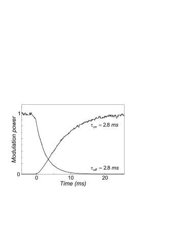
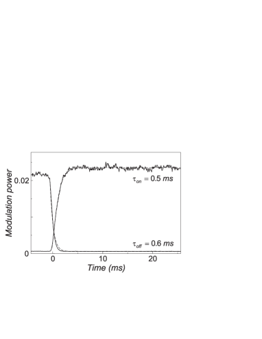
Figure 10 shows the same spectra for a cold damped mirror, with a gain . The two time constants deduced from the fits with Eqs. (51) and (52) are and , both of the same order of magnitude with the one found in the previous paragraph in the study of the relaxation towards the damped regime.
We have therefore shown that the relaxation times of the cold damping mechanism are the ones related to the mechanical response to an external force, with or without feedback.
VIII Conclusion
We have demonstrated that it is possible to actively reduce the thermal noise of a mirror with a feedback loop. The cold damping mechanism described in this paper has allowed us to obtain large noise reductions around the resonance frequency of the fundamental acoustic mode of the mirror, up to . A simple theoretical model, taking into account both the background thermal noise of the other acoustic modes of the mirror and the electronic noise of the loop, allows to explain quantitatively the experimental results. We have also studied the mechanical response of the cold damped mirror, and the transient regime of the cold damping.
We have in particular studied the mechanical response of the cooled mirror to an external force, and we have shown that the cooling mechanism indeed corresponds to a cold damping, where a viscous force is applied on the mirror without any additional thermal noise but the electronic noise of the feedback loop.
We have also studied the transient regime of the cold damping mechanism. We have related the relaxation times when the cooling is switched on or off to the mechanical decay times in response to an external force. Our results show that the cooled regime is much faster to establish than the thermal equilibrium once the feedback is switched off.
The cold damping might be used to perform a cyclic cooling of thermal peaks associated with mechanical resonances of the mirror. One can indeed cool a mechanical resonance during short periods of time, leaving the system unaffected during much longer periods. One then gets a non stationary thermal noise since it is quickly reduced during the beginning of the cycle and slowly increases the rest of the time. If the period of the cycle is properly chosen as compared to the relaxation time of the resonance, the noise will stay well below its thermal equilibrium value. Furthermore, the duration of the cooling phase can be very short if the gain of the feedback is large enough: the system is therefore free most of the time.
Such a cyclic cooling may be used to detect signals corresponding to single bursts of duration smaller than the period of the cycles. For example, one can envision to cool the violin modes in a gravitational-wave interferometer which have sharp resonances within the detection band. Quality factors of these modes are very large so that the period of the cyclic cooling can be made much longer that the expected duration of gravitational waves. For a large feedback gain, the most probable situation is then to detect a gravitational wave when the cooling is switched off. The gravitational wave still has the same effect on the interferometer, whereas the thermal noise is reduced: one then gets a gain in the signal to noise ratio.
Acknowledgements
We gratefully acknowledge Yassine Hadjar for his work on a previous stage of this experiment, Jean-Marie Mackowski for the optical coating of the mechanical resonator, and Jean-Michel Courty and Serge Reynaud for stimulating discussions.
Appendix A
In this appendix, we study the relaxation of the thermal variance between two equilibrium states. In the case where the cooling is applied at , one has to solve equation (48) with initial conditions corresponding to the thermal equilibrium at temperature . The Laplace transform of (48) takes the form
| (53) |
where and are respectively the Laplace transforms of the displacement and of the Langevin force . and are the initial conditions of the oscillator. This leads to
| (54) |
where is the Laplace transform of the effective susceptibility,
| (55) |
can be obtained from Eq. (54) by inverse Laplace transform. It appears as the sum of the response to the Langevin force (first term in Eq. 54) and the transient evolution from the initial conditions :
| (56) |
with
| (58) | |||||
| (59) |
where the temporal evolution of is obtained by inverse Laplace transform of (55):
| (60) |
As and the initial conditions are uncorrelated, the variances of and must be summed,
| (61) |
The Langevin force corresponds to a white noise, therefore its correlation function is
| (62) |
and the variance is equal to
| (63) |
In the limit of a large quality factor of the resonance (), this leads to
| (64) |
where is the variance at room temperature.
At , the mirror is in thermodynamical equilibrium at temperature , thus we get , and Combined with the expression of (Eq. 59), this leads to
| (65) |
The variance is finally equal to
| (66) |
One can derive in a similar way the result when the cooling is switched off at time , by taking in Eq. (48) and initial conditions corresponding to the cooled regime. One gets
| (67) |
Appendix B
This appendix is dedicated to the study of the transient response of the mirror when an external force is switched on or off. Suppose we apply at an external force to the mirror, without feedback. The displacement then obeys
| (68) |
If the response to the external force is much larger than the thermal noise, we can neglect the Langevin force and the initial conditions, which are related to the brownian motion of the mirror. One then gets
| (69) |
where is the same as in Eq. (60), except for the damping . For a monochromatic force , one gets
| (70) |
As , we have a slow increase of the amplitude of a monochromatic spectrum. In that limit, one can compute the temporal evolution of the displacement spectrum at resonance,
| (71) |
In the case where the monochromatic excitation is switched off at , one has to take into account the initial conditions which correspond to the forced regime of the oscillator. The Laplace transform of the displacement obeys
| (72) |
where:
| (74) | |||||
| (75) |
Using the results of Appendix A, one finds
| (76) | |||||
| (77) |
and the corresponding displacement spectrum is
| (78) |
REFERENCES
- [1] C. Bradaschia et al, Nucl. Instrum. Methods A 289, 518 (1990)
- [2] A. Abramovici et al, Science 256, 325 (1992)
- [3] P. Hello, Progress in Optics XXXVIII, ed. E. Wolf, 85 (North Holland, 1998)
- [4] S. Rowan et al, Phys. Lett. A 265, 5 (2000)
- [5] T. Uchimaya et al, Phys. Lett. A 242, 211 (1998)
- [6] S. Mancini, D. Vitali, P. Tombesi, Phys. Rev. Lett. 80, 688 (1998)
- [7] Y. Hadjar, P.F. Cohadon, C.G. Aminoff, M. Pinard, A. Heidmann, Europhys. Lett. 47, 545 (1999)
- [8] P.F. Cohadon, A. Heidmann, M. Pinard, Phys. Rev. Lett. 83, 3174 (1999)
- [9] L. Landau, E. Lifshitz, Course of Theoretical Physics: Statistical Physics (Pergamon, New York, 1958), chapt. 12
- [10] P.R. Saulson, Phys. Rev. D 42, 2437 (1990)
- [11] J.M.W. Milatz, J.J. Van Zolingen, Physica XIX, 181 (1953)
- [12] J.M.W. Milatz, J.J. Van Zolingen, B.B. Van Iperen, Physica XIX, 195 (1953)
- [13] M. Pinard, Y. Hadjar, A. Heidmann, Eur. Phys. J. D 7, 107 (1999)