Toward scalable quantum computation with cavity QED systems
Abstract
We propose a scheme for quantum computing using high-Q cavities in which the qubits are represented by single cavity modes restricted in the space spanned by the two lowest Fock states. We show that single qubit operations and universal multiple qubit gates can be implemented using atoms sequentially crossing the cavities.
pacs:
42.50.Lc, 03.65.-wI Introduction
In the last years, numerous physical systems have been proposed as possible candidates for the implementation of a quantum computer. The desirable conditions which have to be satisfied are a reliable and easy way to prepare and detect the quantum states of the qubits, the possibility to engineer highly entangled states, the scalability to large number of qubits and a very low decoherence rate [1]. Up to now, experimental implementations have involved linear ion traps [2], liquid state NMR [3], and cavity QED systems [4, 5]. In the ion trap case, only the controlled-not (C-NOT) gate between two internal states and the vibrational level of a single ion has been realized [6], and quantum gates involving two or more ions have not yet realized experimentally. A promising step in this direction is the very recent generation of an entangled state of four ions, even if only with fidelity [7]. The status of liquid-state NMR quantum computing is still debated [8], but the fact that the signal strength becomes exponentially small with the number of qubits makes this proposal certainly not scalable to more than about ten qubits. This explains why the research of new physical implementations of a quantum computer is so active (see [9] and references therein). Here, elaborating on the suggestions of Ref. [10], we propose to use the Fock’s states and of a high- cavity mode as the two logical states of a qubit. A quantum register of qubits is therefore a collection of identical cavities in which the state of an appropriately chosen cavity mode is within the space spanned by the vacuum and the one photon state. The register transformations are achieved sending off-resonant two-level atoms through the cavities and making them mutually interacting by means of suitable classical fields. With this respect, the present proposal is similar to that of Refs. [11, 12]; the important difference is that, in these papers, the logical qubits are represented by two circular Rydberg levels of the atoms. In our proposal, the role of atoms and cavity modes are exchanged. In this way, the present scheme becomes scalable in principle. In practice, its scalability can be limited by the spontaneous emission from the Rydberg levels or by other technical limitations, but the present proposal has the advantage that the needed technology is essentially already available to realize some proof-of-principle demonstrations of quantum computation with few qubits. In fact, in the present paper we shall specialize to the case of microwave cavities, for which a high level of quantum state control and engineering has been already experimentally shown [5, 13]. This is the reason why in our explicit calculations we shall consider microwave cavities operating in low-order modes with angular frequency in the GHz range, and Rydberg atoms for which high values of the coupling constant (of the order of ) are possible. It is clear however that, in principle, the method can be applied to optical cavities too, in which one can have a miniaturization of the scheme and therefore a faster operation.
Some preliminary results on the possibilities offered by the present cavity QED scheme have been shown in [14], where some implementations of the C-NOT gate between two cavity modes have been presented. In order to give a clear and exhaustive description, here we shall review the results of [14], which will be extended and generalized in the present paper.
The outline of the paper is as follows. In Sec. II we review the basic properties of the considered cavity QED system. In Sec. III we show how to implement the universal C-NOT gate between two cavities, while in Sec. IV we shall discuss a different scheme for the implementation of universal two-qubit gates, using an arrangement based on that adopted in the experiment of Ref. [13]. In Sec. V we show how single qubit operations can be realized, while Sec. VI is devoted to the implementation of useful many-qubit universal quantum gates as the Toffoli gate and the encoding and decoding network for quantum error correction schemes. Section VII is for concluding remarks, while the appendix shows the explicit implementation of the Deutsch problem [15, 16].
II The system
The interaction of a two-level atom quasi-resonant with a high-Q cavity mode is well described by the time dependent Hamiltonian [17]:
| (1) |
in which and are the annihilation operator and the angular frequency of the cavity mode respectively; and are the excited and lower circular Rydberg state and is their energy difference. Finally is the atom-field interaction Rabi frequency which is time dependent because of the atomic motion through the cavity. In particular for a Fabry-Pérot-type cavity, with Gaussian transverse beam profile, we can assume the following continuous variation
| (2) |
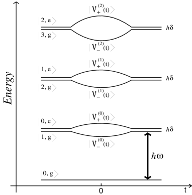
where is the atomic transit time, which depends of course on the inverse of the atomic velocity. For , i.e. when the atom is outside the cavity, the energy eigenvectors of the system are and , with the generic Fock state of the cavity mode. Apart for the ground state which remains unchanged, in the presence of the time-dependent interaction, these terms are coupled by photon emission or absorption, and the istantaneous energy eigenstates at fixed time are the dressed states
| (3) |
with eigenvalues
| (4) |
where is the atom-cavity detuning. Fig. 1 qualitatively shows the time dependence of the dressed levels of Eq. (4) in the case . Now, if the atom velocity is slow enough, and the system for is prepared in a generic energy eigenstate, then in its time evolution it will adiabatically follow this eigenstate, with negligible transitions toward other states [18]. The exact adiabatic condition can be obtained writing the Schrödinger equation in the basis of the vectors , and then neglecting terms coupling the dressed states. The resulting condition is
| (5) |
which, in the limit becomes equal to that given in Ref. [17]. The general adiabatic condition (5) shows in particular that adiabaticity can be obtained even when , provided that is sufficiently small. In the following we shall always work in this adiabatic regime.
III The C-NOT gate
Domokos et al. have shown in Ref. [12] that, using induced transitions between the dressed states, it is possible to implement a C-NOT gate in which a cavity containing at most one photon is the control qubit and the atom is the target qubit. This idea is the starting point for the implementation of the C-NOT between two cavities we propose here. Ref. [12] considers an atom entering adiabatically the cavity so that the joint atom-cavity state is
| (6) |
When the atom is just inside the cavity, a classical field of frequency equal to the energy difference between the dressed states (originating from ) and (originating from ) is switched on for a time interval , so that the following driving Hamiltonian is added to of Eq. (1)
| (7) |
where is the phase of the classical field and is the coupling costant, which depends on the dipole moment of the transition and on the intensity of . Appropriately choosing the value of , it is now possible to selectively couple with these dressed states, leaving the other components of the vector state essentially unperturbed. Moreover, with a suitable choice of the intensity , it is possible to apply a Rabi pulse between the two states. In this way, when the atom exits the cavity, the resulting state vector in the interaction picture, apart for some phase terms, is given by Eq. (6), but with and exchanged. In this way one has realized a C-NOT gate in which, when the cavity (the control qubit) has one photon, the atom undergoes a NOT operation, while when the cavity contains no photons, the atomic state remains unchanged. We shall refer to this gate as the C-NOT(cavity atom).
In a similar manner, we can build also a C-NOT gate in which the roles of atom and cavity are exchanged. Let us assume in fact to tune the frequency to the transition between the dressed state and the state , and apply again a pulse inside the cavity as before. Now, when the atom leaves the cavity, the terms and in the vector state of the system are mutually exchanged with respect to the initial condition Eq. (6). The and components are instead not affected by the interaction with the classical source . This means having realized a C-NOT gate in which, when the atom is in the ground state, the cavity states and flip, while nothing happens to the cavity state for the atom in the excited state. In analogy with the previous case, we refer to this new gate as C-NOT(atom cavity).
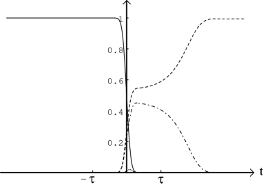
It is important to note that, differently from the C-NOT(cavity atom) case, in the C-NOT(atom cavity) gate the Rabi transition between the original states (i.e. and ) of the dressed states involved is forbidden by selection rules. Nevertheless, this coupling is realizable when the atom is in the cavity because the vector has also a component. However, since this dependence is mediated by a coefficient which decreases with (see Eq. (3)), we have to choose a not too small value of this parameter in order to have a significative coupling constant. In particular, in our calculations we have chosen . With such values for , it is also possible to have a sufficient frequency separation between the transitions we are interested in and all the other ones. Actually, it is sufficient to set the duration of the classical pulse of the order of to discriminate all the parasitic transitions and optimal results for the resulting quantum operation are achieved for kHz, , and with kHz, for the C-NOT(cavity atom), kHz, for the C-NOT(atom cavity). In Fig. 2 we show the time evolution of the dressed states populations for the C-NOT(atom cavity) for the above choice of parameter values.
For quantum information processing one needs to control not only the level populations, but also the relative phases. In general, during the adiabatic evolution, different dynamical phases for the different components of the vector state are generated. However, it is always possible to correct these phases by an appropriate choice of the field phase and eventually acting outside the cavity on the atom with suitable Stark electric fields.
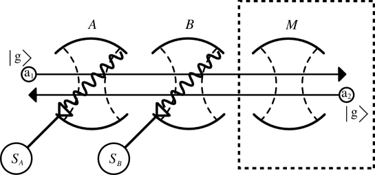
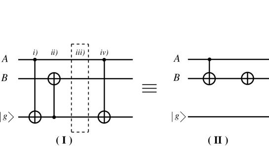
We now have all the elements to realize the C-NOT gate between two distinct but identical cavities, and , with the first one acting as the control qubit and the second one as the target qubit. The apparatus is sketched in Fig. 3 and it is essentially a physical realization of the logical network shown in Fig. 4. Suppose that the initial states of the two cavities are respectively and . i) A first atom, , prepared in the ground state , enters cavity , where it undergoes the C-NOT(cavity atom) transformation realized with the classical field source , and described above. ii) Then leaves and enters cavity : here the classical field is switched on in order to obtain a C-NOT(atom cavity) transformation. In the interaction picture and neglecting all the parasitic but controllable phase terms, the state of the total system at this stage is then:
| (8) |
where is the NOT-conjugate vector of , that is, . iii) and iii) The atom enters again , where it undergoes the C-NOT(cavity atom) transformation, so that the state of the system becomes
| (9) |
In terms of the notations given in the previous section we shall refer to this gate as the C-NOT-INV() gate, in order to underline that undergoes to a NOT transformation when is in the state, while nothing happens when is in the state. This fact is illustrated in Fig. 4, where in the equivalent gate (II) there is a NOT transformation acting on .
The practical realization of step iii), i.e. the return of the atom in the first cavity, is actually more complicated than what it looks from Figs. 3 and 4. The inversion of the motion of atom , could be realized in principle with an atomic fountain configuration. However this implies having free-fall velocities, which are too slow in order to have the necessary interaction times within the cavities. For this reason we propose to transfer the quantum information from this atom onto a second one of the same type, but travelling in the opposite direction. With this respect, the scheme adopts the “quantum memory” scheme experimentally verified in Ref. [19]. This quantum information transfer is implemented introducing a third cavity, the auxiliary cavity of Fig. 3, which, differently from and , is resonant with the transition. If is prepared in the vacuum state , and the transit time of is appropriately chosen, then the atomic state component releases one photon in through a resonant Rabi oscillation. After that, the state of the total system (the three cavities and ), using the same notations of Eq. (8), will be
| (10) |
Notice that the entanglement of with and is now transferred to the auxiliary cavity : the state of the atom is factorized and it can be neglected from now on. At this stage, a second atom is prepared in the ground state and injected into the apparatus with the same absolute value of velocity of , but with the opposite direction. Entering , it absorbes the photon left by the first atom through a similar Rabi oscillation, and the entanglement with the cavities and is transferred from to :
| (11) |
At this stage also the state of the cavity is factorized and therefore the vector state (11) is quantum logically equivalent to that of Eq. (8). In practice, the apparatus described here is essentially an atomic mirror, which permits us to reflect back the atomic state. Finally let us observe that has to cross cavity without interacting with it, before it could reach the cavity . This result is achieved simply by switching off the classical source ; the adiabatic regime and the off-resonance condition prevents that, apart for the dynamical phase factors, the state could change during the transit of within . The action of the C-NOT gate has been explicitely described for factorized state only just to simplify the presentation. It is clear that all the steps can be repeated for a generic entangled state of the two cavities.
Assuming the optimal values for the system parameters written above, we have solved numerically the time evolution of the total system. We describe the resulting effective C-NOT gate in the form of a matrix written in the basis of the Fock states of the two cavities, where : The matrix has been “cleaned up” of the spurious phase factors which may appear during the evolution, and which, using the phase of the classical field and also appropriate Stark shift electrical fields, can always be suitably adjusted. Within a error, the optimized C-NOT matrix has the form
| (12) |
where the non trivial phase . The overall transformation takes place in a time of the order of one millisecond, which has to be compared with the typical decoherence timescales, that is, the atomic radiative lifetimes and the cavity relaxation times. For circular Rydberg atoms with , the atomic radiative lifetime is of the order of and therefore it does not represent a serious problem. The cavity damping times currently realized for microwaves have instead the same order of magnitude (some millisecond). However relaxation times of the order of will be hopefully achieved in the near future, and in this case, one would have a perfectly working C-NOT gate between two cavities. It is clear therefore that, for the present implementation of quantum information processing, the main source of decoherence in the microwave domain is just the cavity leakage. If optical cavities are instead considered, also atomic spontaneous emission may represent an important source of decoherence.
The matrix of Eq. (12) is not a pure C-NOT-INV gate, even if it is still an universal two-qubit gate [20]; in particular it can be transformed into a standard C-NOT gate by adding a single qubit operation on , similar to those we shall present in the following section. Moreover, it is also possible to implement the C-NOT() gate (i.e. the one in which the vector component causes the NOT transformation on , so that the role of the target and control qubit is exchanged), simply preparing the first atom entering the apparatus in rather than in , and then proceeding with the same identical steps of the C-NOT-INV case.
The above scheme assumes the possibility of injecting in the apparatus atomic pulses with exactly one atom: this is not experimentally achieved up to now. However, as shown in Ref. [21], a control of the atom number could be achieved by a modification of the Rydberg atoms preparation technique. The idea is to use an “atom counter” before the circular Rydberg state preparation, so that the preparation of the state (which can have an efficiency near to ) is applied only when one is sure to have exactly one atom. The atom counter is realized by driving a strong transition and measuring the fluorescence, whose intensity wiil be proportional to the number of atoms. When the beam section contains zero, two or more atoms, it is discarded: the system waits then for a time of the order of a few microseconds to twenty microseconds (depending upon the atomic velocity and the precise length of the atomic beam section) until a fresh section of the beam comes in the laser beam driving the fluorescence. In this way, instead of preparing a random number at a given time, one thus prepares with a high probability a single Rydberg atom after a random delay. The average delay is minimal when the probability to have exactly one atom is maximized. With a Poissonian statistics, the optimal mean number of atoms is . The average random delay could be of the order of in realistic experimental condition. This is short enough at the scale of the cavity field lifetime to play no major role in the proposed scheme.
IV Quantum phase gate
In the preceding section we have seen how to implement a universal two-qubit gate, the C-NOT gate, between two cavity modes, using induced transitions between dressed states. However, it is possible to realize another universal two-qubit gate, the quantum phase gate (QPG) [4, 22], between the two cavities, slightly elaborating on the quantum phase gate operating on qubits carried by the Rydberg atom and the two lowest Fock states of a cavity mode, recently demonstrated experimentally [5]. Of course, since both the C-NOT and the QPG are universal quantum gates, it is always possible to implement one of them, by simply supplementing the other one with appropriate one-qubit operations. However, the interesting experimental result of Ref. [5] suggests an alternative physical implementation of quantum logic operations between cavity qubits, which does not involve induced transitions between dressed states, and extends the scheme of [5] to a directly scalable model.
The QPG transformation reads
| (13) |
where and describe the basis states and of two generic qubits. This means that the QPG leaves the initial state unchanged unless when both qubits are in state . In Ref. [5], the QPG of Eq. (13) did not involve levels and , but and , where is a lower circular Rydberg level, which is uncoupled with the high-Q cavity. In this way, the gate of Eq. (13) in the case can be realized by setting the atomic transition perfectly at resonance with the relevant cavity mode (by appropriately Stark-shifting the atomic levels inside the cavity), and by selecting the atomic velocity so that the atom undergoes a complete Rabi pulse when crossing the cavity. In fact, at resonance, such a pulse transforms the state into , while nothing happens if the atoms is in or the cavity is in the vacuum state. In [5], the possibility to tune the phase over a large range, by slightly detuning the cavity mode from the transition, has been shown, but we shall not consider this possibility here.
We now show that this atom-cavity QPG can be used to realize a QPG between two cavity modes, by considering an arrangement very similar to that of the C-NOT gate shown in Fig. 3. The cavities and are again the two qubits, while is again the auxiliary cavity needed to “reflect” the atom and disentangle it. The two classical sources inside the cavities and are no more needed, while we consider the possibility to apply Stark shift electric fields inside the cavities, in order to tune the transition in and out of resonance from the cavity mode. The scheme of the QPG implementation is shown in Fig. 5 and involves only two atom crossings, as in the C-NOT gate of the preceding section, and three pulses between the and levels (the Hadamard gates of Fig. 5), which can be realized with resonant classical microwave sources applied between the high-Q cavities.
Let us assume a generic state of the two cavity qubits
| (14) |
and that a first atom, initially prepared in state , is subject to a pulse, so to enter cavity in state . The cavity mode is perfectly resonant with the transition and the atom velocity is selected so that the atom undergoes a Rabi pulse if it is in state and the cavity contains one photon (the QPG of Ref. [5]). The resulting state at the exit of cavity is
| (15) |
Then the atom undergoes another resonant pulse on the transition and the state of the system becomes
| (16) |
Then the atom crosses cavity , where it is subjected again to the atom-cavity QPG as in cavity , so that the state of the system becomes
| (17) |
At this point, as in the C-NOT case of the preceding section, in order to realize the final transformation and disentangle the atom from the cavities, one has to “reflect” it. This is again achieved with the “atomic mirror” scheme, i.e., using the auxiliary cavity of Fig. 5, that acts as a quantum memory and is able to transfer the entanglement from the first atom to a second atom, which is crossing the apparatus with the same absolute velocity but in the opposite direction (see Eqs. (10) and (11)).
The second atom is then subjected to a pulse before entering the cavities and the state of Eq. (17) becomes
| (18) |
The last step is the QPG between the atom and cavity , i.e., the atom has to cross cavity undisturbed (this is achieved by strongly detuning the transition with a Stark shift field) and then has to undergo another full Rabi cycle in cavity . The final state is
| (19) |
which is desired result, corresponding to a QPG between cavities and with conditional phase shift , and with a disentangled atom.
V One qubit operations
One qubit operations are straightforward to implement on qubits represented by two internal atomic states because it amounts to apply suitable Rabi pulses. This task is less trivial for bosonic degrees of freedom as our cavity modes, because the two lowest Fock states for example are coupled to the more excited ones. The most practical solution is to implement one-qubit operations on the two lowest Fock states sending again atoms through the cavity. To be more specific, one has to send an atom prepared in the ground state through the cavity, with the classical field tuned at the frequency corresponding to the transition between the states and . If one sets the time duration and the intensity of the classical source as in the case of the C-NOT(cavity atom), i.e. such to realize a pulse between the selected levels, one implements a “not-phase” gate, which, in the canonical basis , is described by the following matrix
| (20) |
where depends linearly on the phase of the classical field of Eq. (7) and it is therefore easily controllable (this scheme is simply a part of the C-NOT-INV() gate presented before). If otherwise the atom inside the cavity undergoes a instead of a pulse, one realizes the “Hadamard-phase” gate
| (21) |
where also depends linearly on the classical field phase and is therefore controllable. and can be used to build the more general one-qubit operation and therefore, together with C-NOT-INV(), form an universal set of gates.
Note that the not-phase gate can be used also for an alternative realization of the C-NOT-INV() gate between two cavities. In the scheme described in the preceding section, one needs the auxiliary cavity M and the second atom crossing in the opposite direction in order to disentangle the first atom from the cavities. One could simplify this last stage (step iii) and iv of the preceding section) by applying an exact pulse when the atom has just left the second cavity and the state of the system is that of Eq. (8). The total state becomes
| (23) | |||||
If now the atom is detected by a state-sensitive detector and the state is detected, the two cavities are projected on and one has implemented just the desired C-NOT-INV gate. On the contrary, if the atom is found in the excited state , the state of and becomes and the C-NOT-INV gate is obtained once that cavity is subject to a -phase shift, which can be realized by means of two not-phase gates , the first with and the second with . In this way the atom is disentangled by the measurement. However, the practical application of this scheme is seriously limited by the quantum efficiency of atomic detectors, which is usually far from .
VI Many-qubit gates
A The Toffoli gate
We have shown how to implement a set of universal quantum gates with the proposed cavity QED scheme. Therefore, in principle, the most general quantum operation involving qubits can be realized in terms of the one and two-qubit operations described above. This decomposition however implies a degree of network complexity, and a number of resources and steps which is rapidly increasing with the number of qubits . One of the main advantages of the present proposal is that it is particularly suited for the efficient implementation of many-qubit quantum gates, which, in many cases, can be realized with the same number of steps of the two-qubit C-NOT gate of Section III.
A particularly clear example of the possibilities of the proposed scheme is provided by the Toffoli gate [23]
| (24) |
in which the target qubit is controlled by the first two, and . The effect of the Toffoli gate on the generic three qubit state
| (25) |
( are the tensor product of the cavity mode Fock states) is to exchange the last two components and . The implementation of this gate needs the same arrangement of aligned cavities crossed by Rydberg atoms used for the C-NOT gate of Fig. , except that now one has three cavity qubits (with the corresponding classical sources , and ) instead of two. The auxiliary cavity is again needed for the atomic mirror scheme used to disentangle the atom. The atom is initially prepared in state and when it is in the first cavity , is subject to a pulse between the dressed state and . This pulse creates atom-cavity entanglement and the state of the total system becomes
| (26) |
Then, when the atom reaches the second cavity , it undergoes another pulse, at the new frequency corresponding to the transition between and , so that the transformation
| (27) |
is realized. This means temporarily leaving the logical subspace, even though this allows us to realize a significant simplification of the scheme. The state after this second step is therefore
| (28) |
When the atom enters in , the classical field is applied so to realize the C-NOT(atom cavity ) of Sec. III and the state of Eq. (28) becomes
| (29) |
At this point one has to disentangle the atom from the three cavities and also to adjust the state components in which the cavity contains two photons. Both problems can be solved using again the auxiliary cavity and a second atom crossing the apparatus in the opposite direction as in the “atomic mirror” configuration of Sec. III. The cavity transfers the entanglement with the cavities from the first to the second atom, which is not subject to any classical pulse in . Then the second atom enters , where it undergoes a pulse at the frequency , which simply inverts the transformation of Eq. (27) (thanks to the fact that no term is present), correcting in this way the terms of Eq. (29) in which the second cavity contains two photons. As a consequence, the state of the atom-cavities system becomes
| (30) |
Finally the atom enters , where it is subjected to a pulse resonant with the transition , exchanging with , so that the second atom is disentangled from the cavities and one gets the desired generic output of a Toffoli gate, i.e.,
| (31) |
Notice that in this way we have implemented the Toffoli gate with two atoms only, as in the C-NOT gate of Sec. III. Moreover this scheme can be easily extended to the case of cavity qubits, for the implementation of the n-qubit generalization of the Toffoli gate. We need only two atoms crossing the aligned cavities in opposite directions also in this more general case. The pulse sequence is similar to that discussed above: both atoms undergo a pulse resonant with the transition in the first cavity, while in the following cavities they are submitted to a pulse at the frequency . In the last cavity, the target qubit, the first atom experiences a C-NOT(atom cavity) while the second atom crosses it undisturbed. In the scheme proposed here, the target qubit is necessarily the last cavity. However, it is always possible to realize the n-qubit generalized Toffoli gate with the target qubit in a generic position of the string of cavities, by simply applying a two-qubit operation to the above scheme. In our scheme this means using four atoms at most, and in any case this is much more convenient than realizing this generic n-qubit gate from one and two qubits operation.
B Encoding and decoding in quantum error correction codes
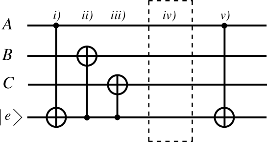
Other examples for which the present cavity QED scheme offers the possibility of an efficient implementation of operations involving many qubits are the encoding and decoding processes used in quantum error correction schemes [24, 25]. Errors in quantum information processing are due to the interaction with uncontrolled degrees of freedom (the environment), yielding an entanglement of the quantum state of the register with some environmental states. The main idea of quantum error correction is to combat “bad” entanglement with “good” entanglement, that is, protecting quantum information by storing it not in a single qubit but in an entangled state of qubits. This is the encoding process; if the error rate is not too large, it is possible to recover the original quantum information by using a suitable decoding procedure, because the eventual data corruption can be revealed by a measurement on the auxiliary qubits and information can be finally restored with single qubit operations. The more general one qubit error (flip error, phase error, or a combination of the two) can always be corrected using a five-qubit encoding and decoding procedure [24, 25]. However, if one considers one specific form of error only, three-qubit encoding is sufficient for the implementation of quantum error correction codes. For simplicity, let us consider this latter case.
Let us assume that we want to protect a generic state of the cavity . For the encoding process one needs two other ancilla qubits, cavity and , and one has to realize the following transformation into a maximally entangled, GHZ state [26] of three cavities
| (32) |
This encoding process can be realized using a scheme analogous to those discussed above for the C-NOT and Toffoli gates. Again, only two atoms are needed, with the second one, crossing the aligned cavities in opposite direction, which serves the purpose of disentangling the first atom, with the help of the auxiliary cavity in the “atomic mirror” scheme described in Sec. III.
The initial state of the system is
| (33) |
When the atom enters it undergoes the C-NOT(cavity atom) described by Eq. (5); when the atom arrives in , the classical field is switched on in order to realize the C-NOT(atom cavity ) transformation (see Sec. III) and the same C-NOT(atom cavity ) operation is applied when the atom is in . Using Eqs. (5) and (6), one can show that the state of the total system becomes
| (34) |
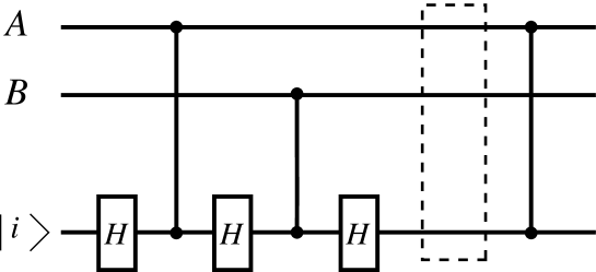
Except for the entanglement with the atom, the state of , and is of the desired form, and therefore the situation is analogous to that of the C-NOT gate of Sec. III (see Eq. (8)). Atom disentanglement can be obtained using again the atomic mirror scheme of Sec. III, or eventually, the atomic detection scheme discussed in Sec. IV, which is however seriously limited by detector inefficiencies. The logical transformations we have implemented in this section is schematically described in Fig. 6 (the dotted line box represents the atomic mirror)
Decoding is obtained by repeating exactly the same procedure adopted for encoding the state and assuming as initial condition for the qubits set the encoded state (32). It is straightforward to check that this amounts to realize the inverse transformation
| (35) |
It is also easy to see that the encoding scheme described here can be extended for the controlled preparation of maximally entangled states of cavities. One has to consider cavities (plus the auxiliary cavity ) and, as in the case, one needs only two atoms crossing in opposite directions the aligned cavities. In analogy with the description above, in the first cavity the two atoms undergo the C-NOT(cavity atom) transformation of Eq. (5), while in all the others cavities the first atom undergoes to a C-NOT(atom cavity) gate and the second one crosses them with no classical field applied. In this way, thanks to the disentanglement action of the second atom, the following maximally entangled state of cavities is prepared
| (36) |
VII Conclusions
In this paper we have presented a scheme for implementing quantum logic operations within a cavity QED configuration. The quantum register is composed by a series of high-Q cavities and information is encoded in the two lowest cavity Fock states. Both the preparation and the detection of the quantum state of individual qubits, which is an essential ingredient in quantum algorithms, can be easily performed. In particular the detection of the two Fock states could be even performed in a quantum non-demolition way, as recently demonstrated [13]. Both one-qubit and two-qubit operations can be performed sending appropriately prepared atoms through the cavities. An important advantage of the scheme is that it is particularly suitable for the direct implementation of some useful many-qubit quantum gates, as for example the Toffoli gate and its n-qubit generalization, or the encoding-decoding network of quantum error correction codes. The scheme could be implemented in a generic cavity QED scheme, even if here we have specialized to the case of microwave cavities and circular Rydberg atoms, for which entanglement manipulation has been already demonstrated [5, 13]. For example, the same scheme could be adapted to the optical frequency domain, by using high-Q optical cavities, as for example the whispering gallery modes of silica microspheres [27], in which one can have a miniaturization of the scheme and, therefore, a faster gate operation. The scheme proposed here is in principle scalable, even if in practice its scalability will be limited by various facts. In the microwave case one is limited by the spontaneous emission from the circular Rydberg levels ( ms) and by the fact that all the apparatus has to be cooled at cryogenic temperatures to avoid the thermal radiation. In the optical case cooling is no more needed and also the limitations due to the spontaneous emission could be avoided in principle by using atomic transitions and adiabatic passage through a dark state [28]. However in the microwave case, the proposed quantum gates could be implemented using available technology, and therefore proof of principle demonstrations of quantum computation with, say, ten qubits could be achievable. Instead, even if whispering gallery modes in microspheres with has been already realized [27], entanglement manipulation in this case have not been experimentally demonstrated yet.
Recently, a similar proposal of using the two lowest Fock states of a high-Q cavity as logical qubit has been presented, involving an engineered network of defects in a photonic band-gap material [29]. This proposal is promising with respect to scalability since, using atoms travelling along engineered waveguides in the photonic band-gap material, spontaneous emission could be completely eliminated. However, even if this proposal is promising in terms of the technological realization, in this case, as in the silica microsphere case, entanglement manipulation has not yet been experimentally demonstrated.
From a general point of view the scheme proposed here is analogous to the linear ion trap scheme, except that now the high-Q cavities play the role of the ions, and the atoms, and not the collective center-of-mass motion, play the role of the quantum bus. At first sight, it may seem unpratical to reverse the role of atoms and photons as we have done here, since the common wisdom is that atoms and ions are suitable for storing informations while photons are best suited to transfer quantum information between different sites. However, the practical implementation of quantum algorithms on linear ion traps is presently limited by the heating of the center-of mass motion [30]. On the contrary, in the case of photonic qubits discussed here, once the limitations due to the spontaneous emission are eliminated (as in the photonic band-gap case and in the microsphere case with dark state transitions), the scheme is then only limited by the decoherence due to the finite of the cavities, which could reach however values of the order of , allowing therefore a sufficient number of gate operations. Moreover, in view of the fact that photons are in any case the best tools for quantum information transport, it may be nonetheless useful to have schemes able to process and temporarily store quantum information using photons.
A A realization of the Deutsch algorithm
As an example of a simple algorithm which can be implemented with the quantum gates presented before we consider the Deutsch algorithm [15] in the improved version of Ref. [16].
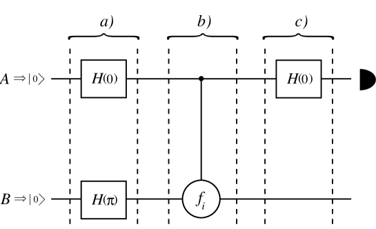
Consider a generic Boolean function mapping into . There are four different possibilities, the two constant functions , , and the two balanced functions , . Using classical algorithms, the distinction between these two different classes of functions necessarily requires that both values of have to be evaluated. On the contrary, the Deutsch quantum algorithm solves the problem in just one step. We have to consider the two cavities quantum circuit of Fig. 7. Initially both cavities are in the vacuum state; then they are submitted to the Hadamard-phase transform of equation (21), with phases equal to and respectively (step of Fig. 7). As shown in Sec. IV, this transformations can be implemented with a single atom prepared in the ground state crossing both cavities. At this point the system undergoes the transformation of step , namely the following “” gate:
| (A1) |
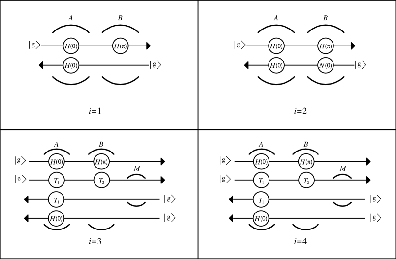
where , are the four functions defined above, and means addition modulo . For , this means that nothing happens to the system; on the contrary for remains unchanged but the second qubit in cavity undergoes a NOT transformation. Finally it is easy to verify that for and for the gate of Eq. (A1) is equivalent to the C-NOT gate and to the C-NOT-INV gate respectively. In the preceding sections we have seen how to implement all these transformations. At stage we have then to implement another Hadamard transformation with zero phase on and measure the state of this qubit. According to the logical network of Fig. 7, it is possible to show that if the of the gate is a constant function, then the cavity must be found in , otherwise, if is a balanced function, the cavity will be in : in this way, one can establish if the function is constant or balanced using a single function evaluation. The physical implementation of the Deutsch problem in terms of the cavities is sketched in Fig. 8. In the case of the constant function it is possible to only use two atoms, because for one atom is needed for the NOT transformation on the cavity of stage and another atom is needed for the Hadamard transform on the cavity at step . For the balanced functions, the number of atoms is instead equal to four, because, besides the two atoms for the implementation of the Hadamard transformations, one has to use two atoms for the C-NOT (if ) or the C-NOT-INV (if ).
REFERENCES
- [1] C. H. Bennett and D. P. DiVincenzo, Nature (London) 404, 247 (2000).
- [2] J.I. Cirac, P. Zoller, Phys. Rev. Lett. 74, 4091 (1995).
- [3] I. L. Chuang, L. M. K. Vandersypen, X. Zhou, D. W. Leung, and S. Lloyd, Nature (London) 393, 143-146 (1998); J.A. Jones, M. Mosca, and R. H. Hansen, Nature (London) 393, 344-346 (1998).
- [4] Q.A. Turchette, C.J. Hood, W. Lange, H. Mabuchi and H.J. Kimble, Phys. Rev. Lett. 75, 4710 (1995).
- [5] A. Rauschenbeutel G. Nogues, S. Osnaghi, P. Bertet, M. Brune, J.M. Raimond, and S. Haroche,, Phys. Rev. Lett. 83, 5166 (1999).
- [6] C. Monroe, D.M. Meekhof, B.E. King, W.M. Itano and D.J. Wineland, Phys. Rev. Lett. 75, 4714 (1995).
- [7] C.A. Sackett, D. Kielpinski, B.E. King, C. Langer, V. Meyer, C.J. Myatt, M. Rowe, Q.A. Turchette, W.M. Itano, D. Wineland, and C. Monroe, Nature (London), 404, 256 (2000).
- [8] S. L. Braunstein et al., Phys. Rev. Lett. 83, 1054 (1999).
- [9] D. P. DiVincenzo, LANL e-print quant-ph/0002077.
- [10] A. Barenco, D. Deutsch, A. Ekert and R. Jozsa, Phys. Rev. Lett. 74, 4083 (1995).
- [11] T. Sleator and H. Weinfurter, Phys. Rev. Lett. 74, 4087 (1995).
- [12] P. Domokos, J.M. Raimond, M. Brune and S. Haroche, Phys. Rev. A 52, 3554 (1995).
- [13] G. Nogues, A. Rauschenbeutel, S. Osnaghi, M. Brune, J.M. Raimond, and S. Haroche, Nature (London) 400, 239 (1999).
- [14] V. Giovannetti, P. Tombesi, and D. Vitali, in press on J. Mod. Opt. (Special issue Entanglement and Decoherence).
- [15] D. Deutsch, Proc. R. Soc. Lond. A 400, 97 (1985)
- [16] R. Cleve, A. Ekert, C. Macchiavello, and M. Mosca, Proc. R. Soc. London Ser. A 454, 339 (1998).
- [17] S. Haroche and J.M. Raimond, in Cavity Quantum Electrodynamics, Advances in Atomic, Molecular and Optical Physics, Supplement 2, edited by P. Berman (Academic Press, New York, 1994), p. 123.
- [18] A. Messiah, Quantum Mechanics (North Holland, Amsterdam, 1962).
- [19] X. Maitre, E. Hagley, G. Nogues, C. Wunderlich, P. Goy, M. Brune, J.M. Raimond, and S. Haroche, Phys. Rev. Lett. 79, 769 (1997).
- [20] A. Barenco et al., Phys. Rev. A 52, 3457 (1995).
- [21] M. Fortunato,J.M. Raimond, P. Tombesi, and D. Vitali, Phys. Rev. A 60, 1687 (1999).
- [22] S. Lloyd, Phys. Rev. Lett. 75, 346 (1995).
- [23] T. Toffoli, in Automata, Languages and Programming, ed. by J.W. De Bakker and J. van Leeuwen, Lect. Notes in Comp. Science, 84, 632 (1980).
- [24] R. Laflamme, C. Miquel,J.P. Paz, and W.H. Zurek, Phus. Rev. Lett. 76,198 (1996).
- [25] E. Knill and R. Laflamme, Phys. Rev. A 55, 900 (1997).
- [26] D.M. Greenberger, M.A. Horne, and A. Zeilinger, Am. J. Phys. 58, 1131 (1990).
- [27] D.S. Weiss, V. Sandoghdar, J. Hare, V. Lefevre-Seguin, J.M. Raimond, and S. Haroche, Opt. Lett. 20, 1835 (1995); M.L. Gorodetsky, A.A. Savchenkov, V.S. Ilchenko, Opt. Lett. 21, 453 (1996); D.W. Vernooy, A. Furusawa, N. Ph. Georgiades, V.S. Ilchenko, and H.J. Kimble, Phys. Rev. A 57, R2293 (1998).
- [28] J.R. Kuklinski, U. Gaubatz, F.T. Hioe and K. Bergmann, Phys. Rev. A 40, 6741 (1990); A.S. Parkins, P. Marte, P. Zoller, O. Carnal and H.J. Kimble, Phys. Rev. A 51, 1578 (1995).
- [29] N. Vats, T. Rudolph, and S. John, LANL eprint quant-ph/9910046.
- [30] D.J. Wineland, C. Monroe, W.M. Itano, D. Leibfried, B.E. King, D.M. Meekhof, J. Res. Natl. Inst. Stand. Technol. 103, 259 (1998).