Motional sidebands and direct measurement of the cooling rate in the resonance fluorescence of a single trapped ion
Abstract
Resonance fluorescence of a single trapped ion is spectrally analyzed using a heterodyne technique. Motional sidebands due to the oscillation of the ion in the harmonic trap potential are observed in the fluorescence spectrum. From the width of the sidebands the cooling rate is obtained and found to be in agreement with the theoretical prediction.
pacs:
PACS: 32.80.Pj, 42.50.Lc, 42.50.VkSince the first preparation of a single atom in a Paul trap and observation of its resonance fluorescence [2], investigation of this light has revealed a range of unique properties. Examples are its nonclassical nature [3] and the highly nonlinear response, in the form of sudden intensity jumps, of a multi-level atom to continuous laser excitation [4]. The fluorescence is, at the same time, a unique tool for determining the state of the atom. This is particularly obvious for a single particle where each photon emission marks the respective projection of the atomic wave function into the final state of the corresponding transition. It is also of great interest to study, through its resonance fluorescence, the motion of a single laser-excited particle, e.g. for investigating laser cooling schemes or in connection with proposals for quantum state manipulation or quantum information processing with trapped particles [5].
The spectrum of fluorescence of a motionless two-level atom exhibits an elastic part (Rayleigh peak) which is -correlated with the exciting light, and an inelastic contribution, the Mollow triplet [6]. While the latter marks spontaneous transitions between the dressed states of the combined atom-light quantum system and appears when the light intensity approaches saturation, the elastic contribution dominates for light levels below saturation. For a free atom this spectrum is modified by the recoil shift. For a trapped atom the elastic peak is unshifted, and sidebands appear at the characteristic frequencies of the motion in the trap [7, 8, 9], with sizes that depend on the amplitude of this motion. The spectral width of these sidebands reflects the effective decay of the motional states of an atom in the trap, i.e. the rate of transitions which change this state. In particular, if laser excitation provides optical cooling of the trapped atom, the sideband width reflects the equilibrium of heating and cooling transitions in the steady state. While such sidebands have been observed in the fluorescence spectrum of ensembles of trapped neutral atoms [10], their investigation for a single particle and analysis of their width has not been done so far [11]. The measurement of cooling rates is highly interesting in experiments with cold atoms or ions, in particular when many levels or several light fields are involved such that an optimal set of parameters is hard to find solely from theoretical arguments.
In this paper we report on a measurement of the resonance fluorescence of a single trapped Barium ion which reveals sidebands of the elastically scattered light due to the various components of the ion’s motion in the trapping potential. From the width of the sidebands which correspond to one of its vibrational modes in the Paul trap quasi-potential we deduce the cooling rate induced by the exciting laser. This method will enable us to perform detailed studies of motional effects of laser radiation in situ, i.e. during the laser excitation without further analysis tools.
In the experiment, a single Ba+ ion is trapped in a 1 mm diameter Paul trap. The ion is generated by impact ionization of a weak thermal Ba atomic beam with an electron beam inside the trap. The trap is suspended in UHV and driven with a 500 Vpp radio frequency signal at MHz. The ion is laser-cooled by simultaneous excitation on its S1/2 P1/2 and P1/2 D3/2 resonance lines at 493.4 nm and 649.7 nm, respectively [12]. See Fig. 1 for the relevant levels of Ba+. The 493 nm light is produced by a frequency doubled diode laser with external grating resonator described in Ref. [13]. This laser is frequency stabilized to a Te2 resonance line 666 MHz away from the Ba+ line, by modulation transfer spectroscopy [14]. The 650 nm light is generated by a diode laser with an external grating resonator, stabilized to an optical resonator. Both lasers have linewidths well below 100 kHz. The laser beams are combined on a dichroic beamsplitter before they are focused into the trap, and both light fields are linearly polarized. The laser intensities at the position of the ion are in the range of 200 mW/cm2 (493 nm) and 100 mW/cm2 (650 nm). The 650 nm laser is close to resonance, the 493 nm laser is red-detuned by about the transition linewidth ( MHz) for Doppler cooling. A 2.8 Gauss magnetic field which is orthogonal to both the laser wave vector and the laser polarization defines a quantization axis and lifts the degeneracy of the Zeeman sublevels. The precise parameters are determined by fitting an 8-level Bloch equation calculation to a scan of the fluorescence intensity vs. the detuning of the 650 nm laser [15].
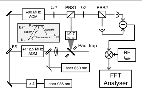
The 493 nm resonance fluorescence of the ion is analyzed with a heterodyne detection setup shown in Fig. 1 [16]. Using a slightly simpler scheme, with a frequency shift in only one arm of the heterodyne setup and with a frequency selective photo detector, Höffges et al. [17] have observed the elastic part of an ion’s resonance fluorescence, but no motional sidebands. In our setup, the fluorescence at right angle to the direction of the laser beams, in the direction of the magnetic field, is collimated with an f/0.7 lens. This light consists of the two -polarized components corresponding to the P to S transitions, and its elastic part is linearly polarized, because the two -polarized components are coherently superimposed. For creating a local oscillator beam, the green laser light is divided into two beams which are frequency shifted by 112.5 MHz (beam 1) and 80 MHz (beam 2) using acousto-optical modulators (AOMs). Beam 1 excites the ion while beam 2 is superimposed with the collimated fluorescence on a polarizing beam splitter PBS1. The beam sizes of the collimated fluorescence and the local oscillator (beam 2) are adjusted for optimum overlap, using telescopes. Their orthogonal polarizations after PBS1 are mixed with a /2 plate and a second polarizing beam splitter PBS2 to create an interference signal. The two output signals of PBS2 are detected on two fast photodiodes (50 MHz bandwidth, 80 quantum efficiency). By subtracting their photodiode currents, the interference term between the fluorescence and the local oscillator is filtered out. Due to the frequency shifts in beams 1 and 2, this interference product (i.e. its elastic part) is expected at a frequency of 32.5 MHz, the difference frequency of the two AOM drives, while any motional sideband due to an oscillatory motion with frequency would appear at 32.5 MHz . The reason for using two AOMs is that their difference frequency is not generated elsewhere in the setup, such that no electrical crosstalk perturbs the final signal, neither can any residual amplitude modulation in one of the beams create a 32.5 MHz signal on the photodiodes. The interference signal is mixed with an rf reference signal at variable frequency around 32.5 MHz, low-pass filtered, and finally analyzed on a Fourier spectrum analyzer with 100 kHz maximum bandwidth. All rf sources, i.e. the trap drive, the AOM supplies, and the rf reference, are phase locked to the same 10 MHz master oscillator.
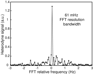
With the mixer frequency set to MHz, the elastically scattered light produces a signal at 50 kHz on the spectrum analyzer. Such a signal, with the resolution bandwidth set to 61 mHz, is shown in Fig. 2. Clearly, only one data point is significantly above the background noise, thus verifying the -correlation between exciting laser and fluorescence. The signal-to-noise ratio (SNR) is 17 dB (at unit bandwidth). The maximum SNR which can be achieved depends on the rate of fluorescence photons that are detected. It is derived in the following way: The spectral power of the signal is , where is the detection bandwidth (or signal bandwidth, whichever dominates), while the noise power is , such that their ratio is . For this to hold, the noise created by with no fluorescence present [18] has to be the dominant noise in the photodiode signal . By varying the local oscillator power without a fluorescence signal we confirmed that this is the case in our experiment and that the noise is close the the quantum limit. With a typical scattering rate of photons/s into the solid angle that is collimated, and with photodiode quantum efficiency, the maximum possible SNR turns out to be 35-40 dB. The comparatively low value of 17 dB which we find is due to phase front distortions induced by the collimating lens and a resulting low degree of mode matching between the collimated fluorescence and the local oscillator.
Due to the quadrupole radiofrequency field in a Paul trap, the ion undergoes a driven oscillation at the frequency MHz. This so-called micromotion is in phase with the driving field, and its amplitude is proportional to the ion’s distance from the trap center. The sidebands to the elastic peak which this oscillation generates can be observed on the spectrum analyser, in the same manner as the carrier, by setting to . In Fig. 3 we show the results of such measurements. Due to the fact that the phase of the micromotion is well-defined, and because all rf sources are phase locked, the width of the micromotion sidebands is limited by the resolution bandwidth of the spectrum analyser, just like the width of the elastic peak in Fig. 2.
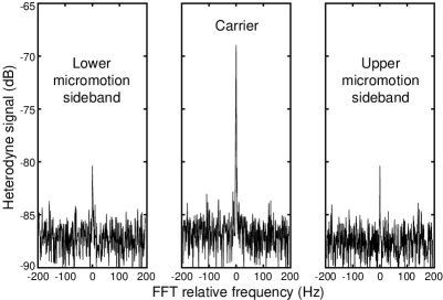
The sizes of the micromotion sidebands are expected to be proportional to where is a Bessel function, is the number of the sideband, and is the modulation index corresponding to the ion’s oscillation. With the micromotion described by , () and with and describing the laser and fluorescence wave vectors, respectively, is given by [17]. The particular value of found from the sidebands in Fig. 3 is 0.47. This corresponds to a micromotion amplitude in the direction of of about 26 nm. By minimising the micromotion, i.e. the value of , with the aid of such a measurement, the ion can be placed in the trap center where the trapping conditions are optimal [19]. At optimum conditions, i.e. if the SNR reaches 40 dB, and , this measurement is sensitive to micromotion amplitudes of about 1 nm.
Apart from the forced micromotion oscillation, the three-dimensional trapping in the rf-generated pseudo-potential of a Paul trap results in three independent modes of free vibration along orthogonal axes at three (in general different) frequencies . In our case, these frequencies are 620.5, 670, 1301 kHz. Investigation of this so-called macromotion is our main purpose, because these motional degrees of freedom interact with the laser in a cooling process, and the corresponding sidebands contain information about the motional state of the ion, the efficiency of the cooling, and their dependences on the laser parameters. It is also the macromotion which is used in experiments on quantum state manipulation and entanglement, in particular in the framework of quantum information and quantum computation [20].
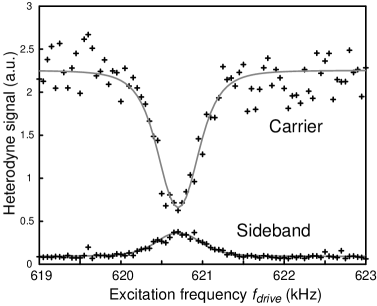
The macromotion is harder to detect in the heterodyne signal than the micromotion because it is not correlated with any applied rf source. In view of the noise considerations above, detection of a macromotion sideband requires that the rate of photons which contribute to the sideband heterodyne signal is larger than the spectral width of that sideband. Due to the inefficient mode matching described above, this situation is not realized in our present setup. However, the macromotion corresponds to a damped harmonic oscillator (laser cooling being the damping mechanism) which can be driven with an additional external field at some frequency close to the macromotion frequency . Then, with set to , the excited macromotion is detectable as a -signal on the spectrum analyser, and a scan of over one of the macromotion resonances reveals the response of that oscillator mode to the drive, in particular the broadening of the resonance due to laser cooling. The result of such a measurement is shown in Fig. 4. Here, the upper trace corresponds to the height of the elastic peak () as in Fig. 2, while the lower trace corresponds to the height of the sideband at (), both as functions of around the 620.5 kHz macromotion mode frequency. The driving voltage was applied to an electrode about 1 mm away from the ion, its power was -60 dBm. The axis of the excited vibrational mode is at 45o between the direction of the laser and the observation, as was found from the image of the ion at much higher drive power.
Fig. 4 shows how the elastic scattering decreases while the sideband scattering increases around the macromotion resonance. The two traces were fitted with functions for the carrier, for the sideband, where was assumed as
| (1) |
as expected for a damped harmonic oscillator. We find a maximum modulation index and a width of the macromotion resonance Hz. This width corresponds to the effective linewidth that the ion’s oscillator eigenstates in the trap acquire due to the ongoing laser excitation which makes the ion change its motional state [8, 9, 17].
To compare this cooling rate with the one derived from a simple model, we describe the motion of the ion by a driven and damped harmonic oscillator. Some limiting conditions are fulfilled in our experiment: The cooling rate is much smaller than the linewidth of the transition , i.e. the velocity changes only negligibly during one lifetime, and both the recoil frequency kHz, being the ion mass, and the maximum Doppler shift are smaller than the oscillation frequency (the latter being the Lamb-Dicke condition). Therefore we can calculate the cooling rate, i.e. the damping coefficient, from the radiation pressure that acts on the ion during its oscillation [21]
| (2) |
where is the probability of finding the ion in the P1/2 state and is the detuning of the 493 nm laser from the atomic resonance frequency. With negative and of the order of , and for the velocity-dependent part of amounts, in first order, to a friction force that the ion experiences [21], and
| (3) |
corresponds to the linewidth induced by the laser cooling. All parameters in Eq.(3) refer to the 493 nm laser. We can neglect the contribution of the 650 nm laser to the cooling because this laser is set to yield maximum fluorescence ( MHz), such that . By calculating from the same 8-level Bloch equations that determine our experimental parameters [15] MHz, , , we get Hz which agrees well with the measurement.
In conclusion, the spectrum of resonance fluorescence from a single harmonically confined ion in a Paul trap was observed using heterodyne detection. Aside from the elastic peak, the spectrum exhibits sidebands due to the weakly excited macromotion of the ion in the trap. Investigation of these sidebands allows for an analysis of the cooling rate, without affecting the motional state of the ion by, e.g., probing pulses. The measured cooling rate in our experiment compares well with a simple model calculation. Moreover, micromotion sidebands are observed which, by minimizing their amplitude, can be used to actively compensate for residual micromotion down to the nm-level. These techniques will prove useful in the context of precision spectroscopy with ion traps and in particular for the preparation and manipulation of vibrational quantum states of motion as they are required for quantum information experiments with trapped ions.
We acknowledge support by the Fonds zur Förderung der wissenschaftlichen Forschung (FWF) (project P11467-PHY) and by the EC (TMR network ”Quantum Structures”, ERB-FMRX-CT96-0077).
REFERENCES
- [1]
- [2] W. Neuhauser et al., Phys. Rev. A 22, 1137 (1980).
- [3] F. Diedrich, H. Walther, Phys. Rev. Lett. 58, 203 (1987); M. Schubert et al., Phys. Rev. Lett. 68, 3016 (1992).
- [4] W. Nagourney et al., Phys. Rev. Lett. 56, 2792 (1986); Th. Sauter et al., Phys. Rev. Lett. 57, 1696 (1986); J. C. Bergquist et al., Phys. Rev. Lett. 57, 1699 (1986).
- [5] D. J. Wineland et al., Journal of Research of the National Institute of Standards and Technology 103, 259 (1998).
- [6] B. R. Mollow, Phys. Rev. 188, 1969 (1969).
- [7] J. Javanainen, Optics Commun. 34, 375 (1980).
- [8] M. Lindberg, Phys. Rev. A 34, 3178 (1986).
- [9] J. I. Cirac et al., Phys. Rev. A 48, 2169 (1993).
- [10] P. S. Jessen et al., Phys. Rev. Lett. 69, 49 (1992).
- [11] Preliminary results have been reported by Bühner and Tamm of PTB, Braunschweig, Germany .
- [12] B. Appasamy et al., Appl. Phys. B 60, 473 (1995).
- [13] Ch. Raab et al., Appl. Phys. B 67, 683 (1998); Appl. Phys. B 69, 253 (1999).
- [14] L. S. Ma et al., Appl. Phys. B 67, 159 (1993);
- [15] M. Schubert et al., Phys. Rev. A 52, 2994 (1995);
- [16] H. J. Kimble, in Les Houches Session LIII, J. Dalibard, J.-M. Raimond, J. Zinn-Justin, eds., Elsevier 1992.
- [17] J. T. Höffges et al., Optics Commun. 133, 170 (1997); T. Höffges et al., J. Mod. Opt. 44, 1999 (1997).
- [18] This corresponds to vacuum field input into the fluorescence port of PBS1.
- [19] D. J. Berkeland et al., J. Appl. Phys. 83, 5025 (1998).
- [20] Ch. Roos et al., Phys. Rev. Lett. 83, 4713 (1999).
- [21] S. Stenholm, Rev. Mod. Phys. 58, 699 (1986).