Fast quantum gates for cold trapped ions.
Abstract
We present an alternative scheme for the generation of a -qubit quantum gate interaction between laser-cooled trapped ions. The scheme is based on the AC Stark shift (lightshift) induced by laser light resonant with the ionic transition frequency. At specific laser intensities, the shift of the ionic levels allows the resonant excitation of transitions involving the exchange of motional quanta. We compare the performance of this scheme with respect to that of related ion-trap proposals and find that, for an experimental realisation using travelling-wave radiation and working in the Lamb-Dicke regime, an improvement of over an order of magnitude in the gate switching rate is possible.
I Introduction
The last few years have seen impressive progress in the experimental demonstration of quantum information processing [1]. Among the growing number of possible physical scenarios for these demonstrations, the system of laser-cooled trapped ions still remains one of the most experimentally attractive [2, 3, 4, 5] (for reviews of ion-trap quantum computing, see e.g. [6, 7, 8]). Ever since the original ion-trap proposal of Cirac and Zoller (CZ) [9], a number of modifications and extensions to their idea have been proposed [4, 10, 11, 12, 13, 14, 15]. Many of these have aimed at bypassing two experimental hurdles of CZ’s proposal, namely: a) cooling the ionic motion to the ground state, while b) at the same time keeping the ions sufficiently far apart that individual laser access to each of them is possible. On the one hand, ‘hot’ gate implementations have been suggested [11, 12, 13] that aim to function even in the presence of moderate motional heating. On the other hand, an ingenious method has been suggested that exploits the ionic micromotion induced by dc offset potentials to address individual ions even while simultaneously illuminating all ions with the same beam [4, 14]. Each of these proposals has its own merits and difficulties, and their feasibility and/or scalability have yet to be demonstrated in experiment. In the meantime, at least one experiment currently under development [5] aims to tackle the two problems directly, achieving the conditions required by CZ.
In the present paper we assume that these conditions will indeed become feasible, and focus instead on another aspect of these experiments: the gate switching rates. Evidently, it is desirable that these should be as large as possible, so that a reasonably complex sequence of quantum operations can be realised before decoherence sets in. It has been remarked [6, 7], that the speed of any 2-qubit gate realised by coupling two ions via a motional mode must be bounded from above by the frequency of that mode (roughly speaking, the ions must be able to ‘realise that they are moving’ before they can influence each other). At the moment of writing, no experiment realising a true 2-qubit ion-ion gate has been reported. However, at least two experiments have used schemes similar to the CZ proposal to implement 2-qubit gates between a single ion and a motional mode [2, 19]. Strikingly, in both cases the reported gate speeds fell far short of the mode frequency, by two to three orders of magnitude. This limitation was not circumstantial, but inherent in the experimental technique that was used. The problem was the existence of strong off-resonant ion-mode transitions, whose unwanted driving would spoil the desired gate dynamics [6, 7, 9]. In order to avoid this, the laser power had to be kept at a relatively modest level, resulting in slow gates. (Very recently, a modification of the CZ scheme which allows somewhat faster gates has been proposed [16], see endnote).
In this paper, we propose a new scheme for 2-qubit gates which should allow an increase in gate speed by at least an order of magnitude with respect to these experiments. Furthermore, this gain is achieved without significant changes in experimental requirements with respect to existing setups, apart from an increase in laser power and good intensity stability. The key feature of our scheme is that it exploits the AC Stark-shift (lightshift) induced by light resonant with the ionic carrier transition. Using a coordinate transformation suggested by Moya-Cessa and co-workers [17] we demonstrate that, within the Lamb-Dicke regime, and at specific shift magnitudes (i.e, laser intensities), the ion-mode dynamics assumes the form of a Jaynes-Cummings interaction [18]. This interaction can be exploited to generate a 2-qubit gate in a manner analogous to the CZ proposal.
We then proceed to compare our scheme with other existing proposals for faster cold-atom gates. For example, already in [9] it has been pointed out that if the travelling-wave radiation used in current experiments is replaced with a standing laser field, with the ion located at a node, then a substantial increase in gate speed would be possible. The elegant ‘Magic Lamb-Dicke parameter’ (MLDP) method proposed by Monroe et al [10] could also in principle lead to faster gates. We argue however that our method, or possibly a combination of it with the MLDP method, is the one most amenable to practical implementation within the cold-ion scenario.
The paper is organized as follows: in the first section, we introduce our gate scheme, explaining its basic principle, the pulse sequences it requires and the ways in which it differs from existing schemes. We also discuss its scalability to many-atom arrays. We then provide numerical confirmation of our analysis, and compare the performance of our scheme with that of the Cirac-Zoller scheme in both its regimes (using travelling- or standing-wave radiation). Finally, we present our conclusions.
II 2-qubit gates based on the AC Stark-shift effect
An important feature of the Cirac-Zoller gate scheme [9] is that the frequencies of the pulses it uses are chosen to be resonant with the transitions between the ‘bare’ (uncoupled) ion-mode levels. This choice reflects a ‘perturbative’ point of view in which these level spacings are assumed to be unaffected by the coupling itself, or in other words that the level shifts due to the AC potential of the coupling field itself can be disregarded. For a sufficiently strong field, this assumption breaks down and the normally disregarded off-resonant transitions become important (see e.g. [6], sec. 4.4.6). A number of authors have speculated that it might be possible to design a gate scheme incorporating these shifts as an integral feature [7, 20]. In this section we construct a concrete realisation of this idea, implementing 2-bit gates by exploiting the lightshift generated by light resonant with the ionic carrier.
A One ion interacting with a travelling laser field
In order to present our underlying idea in its clearest form, we consider first the relatively simple situation of a single trapped ion interacting with a travelling-wave field. Also for simplicity, we assume the relevant ionic levels to be coupled by a direct (optical) transition. As is well-known, the analysis can be straightforwardly adapted to the case of a Raman two-photon transition by a suitable redefinition of parameters [6, 8]. In later sections we demonstrate how the scheme is scalable to traps containing an -ion chain, allowing 2-qubit gates to be realised between the internal states of any two of the ions.
In the standard interaction representation, the Hamiltonian for the one-ion system can be written as [6]
| (1) |
Here, is the laser-atom detuning, the trap frequency, is the Lamb-Dicke parameter of the trap and we have already taken into account a rotating-wave approximation (RWA) that assumes (the detuning is far smaller than optical frequencies).
Let us briefly recapitulate the approach that is usually taken to this problem (see, e.g. [6, 8, 21] and references therein for detailed treatments). First, one expands the exponentials in powers of and looks for the resonances that arise whenever the laser frequency is tuned to a motional sideband, i.e., . A second RWA is then realised, ignoring off-resonant terms which rotate at multiples of the trap frequency . The remaining resonant terms can be interpreted in general as intensity-dependent ‘multiphonon’ transitions [21]. If the Lamb-Dicke parameter is also small , and the ion is sufficiently cooled, the intensity dependence of the coupling constant can be ignored to lowest order in . For example, if the laser is resonant with the carrier transition (), or with the first red sideband (), we have respectively the simple forms
| (3) | |||||
| (4) |
These are the interactions that form the basis of the standard Cirac-Zoller scheme for realising 1- and 2-qubit quantum logic gates [9]. A slight modification of this scheme (using blue-sideband-detuned pulses) has been implemented experimentally in single-ion traps [2, 19].
B 2-qubit lightshift-based quantum gates
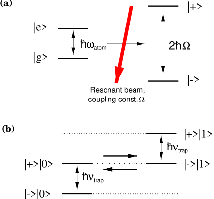
We now demonstrate that, even if only radiation resonant with the carrier is used, and without leaving the Lamb-Dicke limit, there is still a regime where 2-qubit dynamics can be obtained. The basic physical idea behind this is as follows: we know that, apart from driving the 1-qubit transition described in Eq.(3), any radiation resonant with the carrier will also lead to an AC level-splitting of the ionic semiclassical dressed states (Fig. 1) [22]). The magnitude of the splitting is , where , is the Rabi frequency. When the intensity of the laser is such that the splitting equals exactly one vibrational energy quantum , the levels and become degenerate, and we can expect transitions between them (Fig. 1). This amounts effectively to an exchange of excitation between the motional and internal states, i.e., to 2-qubit dynamics.
To see how this happens in detail, let us begin by first making the Lamb-Dicke approximation (to first order in ) directly in eq.
| (5) | |||||
| (8) |
(where we have defined ). When the radiation is resonant with the ionic transition (or ‘carrier’) frequency , this reduces to
| (9) |
Comparing with eq. (3), we see that the usual derivation corresponds to neglecting the terms rotating at frequency in this expression. These terms are the first order correction to the semiclassical ion-field interaction due to the presence of the trapping potential, and their effect is to cause the dressed states to become nonstationary. To see how these evolve, we first move into the ‘dressed-state’ picture obtained by rotating the atomic basis states with the transformation
| (10) |
so that become respectively and (note that, in our notation, , , , ).
Using the fact that
| (11) |
we can see that, in this picture, the Hamiltonian has the Jaynes-Cummings [18] form
| (12) |
(This transformation of the Hamiltonian is a special case of the construction given in [17], where it is shown that the ion-laser interaction is always unitarily equivalent to a Jaynes-Cummings form, without any approximations).
Making a further ‘interaction picture’ transformation of the Hamiltonian by the unitary operator , we have
| (13) |
which gives us the resonance condition
| (14) |
Apart from the small correction to given by the Debye-Waller factor [6], this is precisely the condition depicted in Fig. 1. In this case, the first two (‘rotating’) terms in Eq. (13) become constant while the second two (‘counter rotating’) oscillate at frequency . We can ignore them, making the Jaynes-Cummings RWA, as long as the secular frequency of the resulting evolution is much smaller than this [18]. This requires , which is compatible with the Lamb-Dicke assumption we have already made. Thus, if the laser’s frequency and intensity are such that they satisfy the double resonance condition , the evolution of the system can be described by the simple Jaynes-Cummings form
| (15) |
What this teaches us is that off-resonant transitions cannot always be disregarded, but, under the right conditions, may in fact lead to resonant effects. Intuitively, if the off-resonant terms in the Hamiltonian given in eq. (9) rotate precisely in step with the secular evolution generated by the resonant terms, their contribution does not ‘average out’ but rather adds up over each cycle, in a manner reminiscent of an oscillator being driven by a resonant force. In the present case this effect allows a field resonant with the carrier to couple the internal and motional ionic variables in a way exactly analogous to a red-sideband-detuned pulse as described by eq. (4) (Fig. 2). In particular, it can just as well be used to implement -qubit logic gates between these two degrees of freedom. Of course, the Hamiltonian (15) is valid only in the ‘dressed’ picture defined by the operator in eq. (10). In the normal or ‘bare’ picture, its effect can be seen as a beating at frequency superposed on the usual Rabi flops between states and (Fig. 2). It is not necessarily obvious that this ‘dressed-picture’ Jaynes-Cummings interaction can be used to implement quantum logic gates in the ‘real world’. Nevertheless, in the next section we show how, with a suitable generalisation to the -ion situation, this interaction can indeed realise a Control-NOT (C-NOT) gate between the internal variables of two separate ions. (Recall that a C-NOT gate together with one-qubit rotations form a universal set of gates for quantum computing [29]).
Finally, let us briefly consider the experimental requirements of our proposal. Apart from the usual demands of the CZ quantum gate proposal (individual ion access, ground-state cooling), the only new requirement we make is that the laser should have a fixed intensity satisfying the resonance condition in eq. (14) (or its -ion generalisation, see below). In more quantitative terms, our numerical simulation (see section III B 1) indicates that the laser power must be stable to within about . This does not seem to require significant improvements in the laser power and intensity stability already available in current experimental setups [24]. There is also a bonus in the fact that a single laser can be used to perform both 1- and 2- qubit interactions. Therefore, we expect that a proof-of-principle experiment using a single trapped ion should not be hard to realise.
C Lightshift gates in a chain of N ions
The results we have just described are almost immediately generalisable to the case where there are identical ions (and therefore motional modes) in a linear trap [6, 8]. Assuming that each of the ions can be illuminated individually by a (travelling) laser beam, then resonance conditions similar to eq. (14) turn out to exist for each separate mode frequency . Before showing how the resulting ion-mode interaction can be used to implement ion-ion gates, we would like to call attention to an important aspect of the -ion situation. In principle, any of the motional modes can be used to couple the internal ionic variables. However, in order for the lightshift scheme to function with higher-order modes it is necessary to drive the system deeper into the Lamb-Dicke regime. To see this, consider the interaction-picture Hamiltonian describing the coupling of the ion with a (travelling-wave) laser [8]
| (16) |
Here, indexes the normal modes. The parameter which functions as the ‘effective’ Lamb-Dicke parameter of the mode, corresponds to the product , where is the ‘conventional’ Lamb-Dicke parameter and is the relative weight of the ion’s displacement in this mode. For the centre-of-mass mode, is independent of which ion is being driven. For other modes this is no longer true. James [8] has given values of for all ions and modes up to .
If all modes are suitably cooled and within the Lamb-Dicke regime, and if the laser is resonant with the ionic carrier transition , then a procedure entirely analogous to the one described in eqs. (8-13) can be followed. One then obtains that, in the ‘dressed-state’ picture defined by
| (17) |
the Hamiltonian given above can be rewritten as
| (18) |
where . As expected, there are multiple resonance conditions analogous to eq. (14), one for each mode frequency If any of these are met (say, for the mode), then the terms in this Hamiltonian can be divided into three categories according to their time-dependence: (1) The rotating terms of the mode are resonant, and represent a Jaynes-Cummings interaction of the form
| (19) |
(2) All counter-rotating terms oscillate at frequencies equal (in modulus) to at least , where is the lowest energy mode. Assuming the effective Lamb-Dicke parameter is small , they can therefore can be discarded in a RWA. (3) The rotating terms of the other modes oscillate at frequencies equal to . For a similar these terms can be discarded as long as
| (20) |
If this is true for all , then the Hamiltonian (18) can be reduced to the resonant term given in eq. (19). In this case, only the mode is coupled to the ion’s internal state, just as in the usual perturbative scheme when the laser is tuned to the first red sideband of this mode. The off-resonant terms will lead to a small population leakage into the unwanted modes, of order
| (21) |
As we discuss in appendix A, for high enough precision (small enough ), this population loss gives an upper bound to , and therefore to the overall Rabi frequency at which the scheme can function. For example, in the case of the lowest (center-of-mass) mode, requires . In addition, it has been shown by James [8] that the spacing between successive modes decreases as their order increases. It follows that attaining a given precision requires to be made smaller and smaller as grows. In effect, we find that the potential increase in Rabi frequency afforded by using higher modes is completely counterbalanced by this requirement, with the result that the maximum value for the overall switching rate actually decreases as higher modes are used.
D 2-ion CNOT gates
Assuming the effective Hamiltonian (19) is valid, we can use it to implement 2-qubit quantum logic gates between two ions in a manner similar to the usual Cirac-Zoller (CZ) scheme [9]. The analogy is not perfect because in the present case the Jaynes-Cummings Hamiltonian is valid only in the picture defined by the unitary operator in eq. (17), which varies according to which atom is being addressed. Before we realise a gate, we must first transform back into the ‘common’ picture (i.e., the one where the Hamiltonian in eq. (16) is defined) and see how the time evolution behaves there. In this case we have that an initial state evolves according to
| (22) |
where is given in eq. and . In particular, the following states have a simple time evolution:
| (23) | |||||
| (25) | |||||
| (27) | |||||
| (29) | |||||
As we can see, we obtain the usual Jaynes-Cummings Rabi flops, except that here the atomic states for which the atom and mode dynamically entangle and disentangle themselves are the dressed states , not the bare states . There are also some additional time-dependent phases.
In Appendix B, we demonstrate explicitly how this evolution can be used to implement a 2- qubit gate between two ions. We follow the same basic three-step pulse sequence proposed by Cirac and Zoller [9]: first, a -pulse is realised between ion 1 and the chosen vibrational ‘data bus’ mode, which is initially cooled to the ground state. This effectively maps the internal state onto the motional one and vice-versa, implementing the so-called SWAP gate. Second, a -pulse is applied between the mode and ion 2, realising an entangling gate between the two systems. Finally, a second -pulse maps the motional state back onto the first ion, completing the ion-ion gate. In the lightshift scheme, some minor modifications in the sequence are necessary due to the fact that the ‘computational basis states’ of the ions (generally assumed to be the bare states ) are not favoured by the time-evolution above. This will then require a few extra -qubit rotations in between the three basic steps. In the end, we are able to implement a C-NOT gate, with ion 2 acting as the ‘control’ qubit, using a sequence of six pulses (three 1-qubit and three 2-qubit pulses). In comparison, the original CZ proposal requires pulses to implement a C-NOT gate, with the ions assuming the opposite roles: ion 1 is the ‘control’ and ion 2 the ‘target’ qubit. We note that, in our protocol, some of the 1-qubit pulses may (at least in principle) be realised simultaneously with a 2-qubit pulse: pulses 1 and 2 in Appendix B can realised together, and the same is true of pulses 4 and 5. In contrast, in the CZ scheme each of the five pulses must be realised in sequence.
III Comparative performance of gate schemes
We now study the performance of our ‘lightshift-based’ (LB) gate scheme, comparing it to that of Cirac and Zoller’s original ‘red-sideband pulse’ proposal [9]. Briefly speaking, our goal is to estimate the overall switching rate for an ion-ion C-NOT gate that can likely be attained using each scheme.
We begin by recalling that this rate will be essentially governed by the speed of the three 2-qubit steps in either scheme’s pulse sequence. This follows since 1-qubit ionic gates are unlimited by the mode frequency, and can therefore be implemented at a much greater speed than 2-qubit ion-mode pulses [6]. If we also assume for simplicity that the same ionic transition is used for both and pulses, then the overall ion-ion gate frequency should be approximately equal to the 2-qubit Jaynes-Cummings Rabi frequency. Here we are using the convention that one complete Rabi oscillation, i.e., when all states and their phases have returned to their initial values, corresponds to a pulse.
For the LB scheme, this frequency is just . For a typical value of the Lamb-Dicke parameter, we obtain therefore an overall C-NOT switching rate of about . Although still well under the limit posed by the mode frequency itself, such a rate would represent a substantial improvement with respect to current experiments. For example, in the (single-ion) 2-qubit gate experiment reported in [2], the 2-qubit Rabi frequency was approximately . In what follows, we elaborate on this comparison by making a more thorough analysis of the limits of validity of the two methods. In particular, we include numerical confirmation of the efficiency of the LB scheme.
A Regimes of the Cirac-Zoller scheme
Unlike in the LB scheme, in the CZ method the speed of the 2-qubit gates is directly proportional to the laser field used to drive the red-sideband transition. This field cannot however be made too intense without driving unwanted off-resonant transitions, which therefore are the limiting factor on the resulting gate speed. Before we can properly assess this limit quantitatively, we must first recall that the CZ scheme operates in two strikingly different regimes, depending on the spatial profile of the laser field [9, 20]. The origin of this difference lies in the presence or not of strongly coupled off-resonant levels. It turns out that the conditions under which transitions to these levels can be safely ignored (as is implied in the derivation of the CZ scheme) depend crucially whether travelling-wave or standing-wave laser radiation is employed to drive the red-sideband transition
When a travelling beam is used, the closest-lying off-resonant transition is the carrier transition itself, which is detuned by the mode frequency . Despite this, the carrier is also stronger than the resonant transition by a factor of . Intuitively, this situation is analogous to a V-type 3-level atom where a weak transition (of strength ) is being resonantly driven, and where there is another closely lying transition, detuned by , which has a much stronger coupling constant (Fig 3). The effects of both transitions must then be carefully weighed against each other: if is large with respect to , then we may expect the off-resonant transition to be ‘washed out’ on average, as happens in usual rotating-wave approximations. However, this condition alone is not sufficient, since in the limit the off-resonant transition must dominate the time evolution, resulting in oscillations with effective Rabi frequency . We can therefore expect the resonant transition to dominate only if its secular Rabi frequency is much greater than this value, i.e. if
| (30) |
The validity of this heuristic argument for the actual Cirac-Zoller Hamiltonian can be confirmed via a straightforward perturbation-theory calculation [27].
In other words, in order to ignore off-resonant transitions the Rabi frequency of the ion-mode interaction must be extremely small, of the order for a typical value . This in turn implies that the switching rate of the resulting logic gates will be of order , way below the upper limit set by . It is worthwhile to note that eq. (30) was indeed satisfied in both published experiments that implemented CZ-like Rabi flops using travelling-wave radiation and a single trapped ion [2, 19].
A very different situation arises if the laser field forms a sinusoidal standing wave (such as could be obtained by bouncing the beam back on itself from a mirror), and if the ion is located exactly in one of the nodes of this wave. In this case, interference from the two travelling components of the wave completely cancels many of the off-resonant transitions, in particular the carrier [6, 8, 9]. This effective selection rule greatly increases the laser power that can be used, since the most important off-resonant terms remaining in the Hamiltonian (Jaynes-Cummings counter-rotating terms and terms describing the accidental driving of the wrong modes) are no longer stronger than the resonant one. Standard perturbation-theoretic arguments [20, 8] show that in this case the laser power should satisfy
| (31) |
For , this implies an increase by two orders of magnitude with respect to the travelling-wave case. As a result, this configuration could potentially lend itself to the implementation of much faster gates than the ones already achieved experimentally. Unfortunately, the technical difficulty of reliably maintaining an ion precisely in a wave node seems to have discouraged researchers from attempting such an experiment [26]. We are also not aware of any current plans for experiments in this direction.
B Efficiency of gate implementations
In what follows, we compare our ‘lightshift-based’ proposal to both regimes of the CZ scheme. We find that its performance can approach that of the standing-wave CZ configuration, without the latter’s technical drawbacks. In other words, an improvement of over an order of magnitude in the switching rate can be achieved with respect to current travelling-wave-based experiments without a great change in the experimental setup itself. It must be emphasised again that we are only interested here in the theoretical limits to the gate performance, arising exclusively from the existence of stray off-resonant excitations in the system. In other words, we are not concerned with external noise or dissipative effects such as spontaneous emission [25], but with the maximum performance obtainable even under ideal experimental conditions.
A useful figure of merit for comparing the performance of the different schemes can be defined as follows. First, we determine how efficiently the -pulse (or ‘SWAP gate’) step is implemented in each scheme as a function of a relevant external parameter of the system, for instance laser power (a precise definition of what me mean by ‘efficiency’ is given below). We can then define the maximum switching rate for each scheme as the greatest speed that can be attained while simultaneously keeping the efficiency above a sufficiently high threshold, which we (arbitrarily) set at 99%.
The definition of ‘efficiency’ is also somewhat arbitrary. We take it to be the average fidelity with which the SWAP gate operates, maximized over one cycle, or
| (32) |
where the average is taken over some set of ‘relevant’ initial states , with ideal images under SWAP given by , and where represents the full time evolution of the ion-trap system. For simplicity, we take this set to be the basis states (in the case of the CZ gate) or (in the case of the LB gate).
1 Numerical results
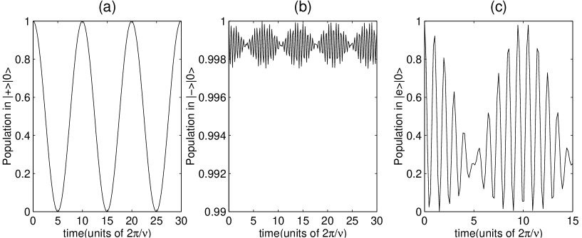
In Fig. 4 we plot the efficiency function F(), with fixed at 0.1, for three different gate schemes: the CZ scheme using (a) travelling-wave radiation or (b) standing-wave radiation; and (c) the ‘lightshift-based’ scheme. The graphs were obtained by numerical integration of the full Schrödinger equation describing an ion-CM mode interaction in a two-ion trap, including all off-resonant transitions and all orders of the Lamb-Dicke parameter. The second or ‘stretch’ mode is assumed to be cooled to the ground state.
As should be expected, in the CZ schemes the efficiency decreases essentially monotonically with the laser power. In addition, the dramatic difference in performance between the standing- and travelling-wave CZ configurations is readily apparent (note the difference in scale of the two graphs). Indeed, if we consider 99% efficiency as the criterion for acceptable gate performance, then the upper limit for in the travelling-wave case is about , while in the standing-wave case about , in agreement with the estimates in eqs. (30) and (31). Meanwhile, the efficiency of the LB scheme has a narrow peak around the resonance value , with a maximum value well over 0.99. (This is in good agreement with eq. (21), which predicts a population leakage of into the stretch mode). The width of the region where is of the order of . We can conclude that highly efficient gate performance in this scheme is possible as long as the Rabi frequency of the laser-ion interaction is stable to within at least .
C Discussion
Our results indicate that, as long as the challenges of individual laser access and ground-state cooling can be met, the lightshift-based scheme should indeed allow highly efficient 2-qubit gates to be implemented within the Lamb-Dicke regime. Furthermore, the relatively high laser power employed in this scheme means these gates should be over an order of magnitude faster than their counterparts obtainable via the travelling-wave CZ scheme used in current experiments. Specifically, an ion-ion C-NOT gate with switching rate around may be realised. This speed is comparable to the one obtainable in principle with a standing-wave CZ configuration, but our proposal achieves it without requiring a precisely controlled standing-wave field. We believe that these features should make the lightshift-based scheme a attractive candidate for the realisation of faster quantum gates. Furthermore, testing the underlying principle of the scheme in existing single-ion traps should present no difficulty.
Finally, we would like to briefly compare our scheme with the ‘magic Lamb-Dicke parameter’ (MLDP) proposal of Monroe et al. [10]. This elegant scheme exploits the fact that the 1-qubit Rabi frequency in eq. (3) is in fact dependent on the number of motional excitations of the ion. It turns out that, for specific ‘magic’ values of the Lamb-Dicke parameter, the values of corresponding to zero and one phonons become commensurate. This then means that, after a sufficient number of Rabi periods, the atomic state is flipped or not depending on the state of the mode, in other words a C-NOT gate with the mode as control qubit can be implemented. The scheme has a number of experimental advantages, notably the absence of the ‘auxiliary’ level needed in the CZ and LB schemes. Also, since it only uses the strong ionic ‘carrier’ transition, the laser power used can be quite considerable, leading also to relatively fast gates. The exact switching rate that can be obtained depends on the chosen ‘magic’ value, but should be as least as large as the ones obtained by the other methods discussed in this paper (see [16] for a discussion).
The method however has also at least two drawbacks. First of all, even the smallest ‘magic’ value of quoted in [10] is 0.316. This is already a bit too large for the validity of the Lamb-Dicke regime required by currently used cooling mechanisms such as sideband cooling [6]. Unless more sophisticated cooling methods are employed (possibly involving the use of higher-order sidebands [28]), one would then need the ability to fine-tune to different values at different stages of the experiment, a feat that has not yet been accomplished in practice to our knowledge.
A second drawback comes the fact that the MLDP scheme can only implement universal ion-ion quantum logic [29] if it is supplemented with another mechanism capable of realising SWAP gates between internal and motional states. For example, in [10], Monroe et al point out that an ion-ion C-NOT gate can be realising by “sandwiching” an MLDP-based ion-mode C-NOT between two SWAP gates, just as happens in the CZ scheme. However, the dispersive interaction exploited in the MLDP scheme does not itself allow the transfer of excitations from the internal to the motional states. This can be seen by noting that none of the available gates (1-qubit ionic rotations and C-NOT gates with the mode as control qubit) changes the populations in any motional state. (In other words, these operations alone do not constitute a universal set of gates [30]. SWAP gates can only be realised via some different mechanism, for instance the CZ red-sideband method or our LB method. In particular, a gate using LB-based SWAP steps and an MLDP-based entangling step would combine the best features of both these schemes, including both speed and the absence of complications such as auxiliary levels and standing waves (Note though that, since the LB scheme requires a smaller value of , the ability to tune this parameter would still be required). Whether in this “hybrid” combination or on its own, we hope that the LB scheme will prove to be a useful tool for ion-trap quantum information processing.
Endnote: Shortly after this work was submitted, another study of the speed limits of Cirac-Zoller gates was put forward by Steane et al. [16]. Apart from presenting results which support and extend the discussion in section IIIA above, these authors also propose and experimentally test an independent method for increasing the gate switching rates within a travelling-wave scenario. Their idea is somewhat complementary to the one presented in this paper: they argue that the rapid decay in gate efficiency shown in fig. 4a) is partly due to a shift in the sideband transition frequency caused by the nearby strong carrier transition. This shift can be compensated for by choosing the laser beam to be slightly detuned from the first sideband frequency, resulting in gates that are considerably faster than the “standard” CZ gates we have considered in our analysis. Nevertheless it appears that, if a sufficiently high gate fidelity is demanded, then our lightshift-based scheme is still faster than even this enhanced scheme [31].
Acknowledgements: We thank Dana Berkeland, Chris Monroe, H. Christoph Nägerl, Juan Poyatos, Danny Segal, Andrew Steane, Jörg Steinbach, and Antônio Vidiella-Barranco for suggestions, clarifications and comments. We acknowledge the support of the Brazilian agency Conselho Nacional de Desenvolvimento Científico e Tecnológico (CNPQ), the ORS Award Scheme, the United Kingdom Engineering and Physical Sciences Research Council, the Leverhulme Trust, the European Science Foundation, and the European Union.
A Limits to lightshift gates in N-ion strings
James [8] has given detailed numerical data for the mode parameters of up to trapped ions. It turns out that the frequency of a mode of any given order is roughly independent of the number of ions (to about over the range of ion numbers investigated). In the second line of the table below we reproduce these rough frequency values for the first six modes, relative to the frequency of the lowest (CM) mode [23].
| 1 | 2 | 3 | 4 | 5 | 6 | |
|---|---|---|---|---|---|---|
| 1 | 2.41 | 3.06 | 3.68 | 4.28 | ||
| 0.39 | 0.27 | 0.20 | 0.16 | |||
| 0.146 | 0.08 | 0.05 | 0.04 | 0.03 | ||
| 0.073 | 0.069 | 0.065 | 0.061 | 0.055 |
We can use this data along with the condition in eq. 21,i.e.
| (A1) |
in order to estimate the range of values of the Lamb-Dicke parameter for which the lightshift-based scheme should work within a given precision. (It can be verified that losses due to other off-resonant transitions such as the counter-rotating terms in eq. (18) are relatively small in the limit of small ). For each mode, we list in the third line the relative frequency spacing to its closest-lying neighbour. Note that the closest mode is always the next-highest one, and that their relative spacing decreases with increasing mode order. In the fourth line, we list the maximum value that can assume such that . Within this limit we should be able to discard all off-resonant terms in the Hamiltonian in eq. (18), and the dynamics is then well described by the effective Jaynes-Cummings interaction in eq. (19). Finally, in the fifth line we give the resulting maximum Rabi frequency achievable using each mode (relative to the CM mode frequency). Note that the increase of the mode frequencies themselves is completely compensated by the decrease in the allowed Lamb-Dicke parameters, with the effect that the overall Rabi frequency also diminishes as the mode order is increased.
B C-NOT gate in the Lightshift scheme
The following sequence of pulses realises a C-NOT gate between the internal states of two trapped ions, using the LB ion-mode interaction given in eqs.(23-29).
-
1.
First, assuming the ‘bus’ mode is initially in the ground state, the state of ion 1 in the basis is mapped onto the and phonon states by a 2-qubit -pulse of duration
(B2) (B3) The phase is identical for both initial states and can be ignored; ion 1 is left in the state. In terms of the logical basis , this transformation corresponds to applying a sequence of three gates: first a Hadamard rotation of the ion, followed by a SWAP gate with the mode, and finally a second Hadamard rotation.
-
2.
A 1-qubit pulse coupling to an unpopulated ‘auxiliary’ level is then applied on ion 2, mapping . As in the CZ scheme, this transition should be chosen such that level is not affected (for instance by using a different polarization).
-
3.
A 2-qubit pulse of duration resonant with the transition, is applied on ion 2. States and of the ion-mode system are unaffected by this, while states evolve according to
(B5) (B6) -
4.
Another 1-qubit pulse coupling to is then applied, mapping back to For convenience, we assume here that this pulse also cancels the phase acquired in the previous step. The overall effect of the previous three pulses is to implement a ‘control-’ gate between the mode and ion2, which maps
(B7) (B8) -
5.
The state of the mode is then mapped back onto ion 1 by a second -qubit pulse
(B10) (B11) -
6.
Finally, a 1-qubit pulse removes the phase acquired in the previous step, mapping states of ion 1 into . This completes the gate, whose overall effect in the computational basis is a C-NOT between ion 2 (the control qubit) and ion 1 (the target qubit):
| (13) | |||
| (14) | |||
| (15) | |||
| (16) |
Note that the first five pulses already generate a ‘maximally entangling’ -qubit gate, equivalent to the C-NOT gate except for a local rotation.
REFERENCES
- [1] For a pedagogical introduction to quantum information theory, see e.g. J.Preskill, lecture notes for Caltech course 229, available at http://www.theory.caltech.edu/people/preskill/ph229/. For an overview of experimental achievements, see e.g., Physics World (1998). For a survey of more recent developments, see e.g., J. Mod. Opt., 47, issue 2/3 (2000) (Special Issue on Quantum Information, eds V. Bužek and D.P. DiVincenzo), and references therein.
- [2] C. Monroe, D.M. Meekhof, B.E. King, W.M. Itano and D.J. Wineland, Phys. Rev. Lett. 75, 4714 (1995).
- [3] B.E. King, C.S. Wood, C. J. Myatt, Q. A. Turchette, D. Leibfried, W. M. Itano, C. Monroe, and D. J. Wineland, Phys. Rev. Lett. 81, 1525 (1998).
- [4] Q.A. Turchette, C.S. Wood, B.E. King, C.J. Myatt, D. Leibfried, W.M. Itano, C. Monroe and D.J. Wineland, Phys. Rev. Lett. 81, 3631 (1998).
- [5] H.C. Nägerl, D. Leibfried, H. Rohde, G. Thalhammer, J. Eschner, F. Schmidt-Kaler and R. Blatt, Phys. Rev. A 60, 145 (1999).
- [6] D.J. Wineland, C. Monroe, W.M. Itano, D. Leibfried, B. King and D.M. Meekhof, J. Res. Natl. Inst. Stand. Technol. 103, 259 (1998).
- [7] A. Steane, App. Phys. B 64, 623 (1997).
- [8] D.F.V. James, App. Phys. B 66, 181 (1998).
- [9] J.I. Cirac and P. Zoller, Phys. Rev. Lett. 74, 4091, (1995).
- [10] C. Monroe, D. Leibfried, B.E. King, D.M. Meekhof, W.M. Itano and D.J. Wineland, Phys. Rev. A 55, R2489 (1997).
- [11] J.F. Poyatos, J.I. Cirac and P. Zoller, Phys. Rev. Lett. 81, 1322 (1998).
- [12] A. Sørensen and K. Mølmer, Phys. Rev. Lett. 82 , 1971 (1999); A. Sørensen and K. Mølmer, quant-ph/0002024
- [13] S. Schneider, D.F.V. James and G.J. Milburn, J. Mod. Opt. 47, 499 (2000).
- [14] D. Leibfried, Phys. Rev. A 60, R3335 (1999).
- [15] E. Solano, R.L. de Matos Filho and N. Zagury, Phys. Rev. A 59, R2539 (1999).
- [16] A. Steane, C.F. Roos, D. Stevens, A. Mundt, D. Leibfried, F. Schmidt-Kaler and R. Blatt, quant-ph/0003087.
- [17] H. Moya-Cessa, A. Vidiella-Barranco, J.A. Roversi, D.S. Freitas and S.M. Dutra, Phys. Rev. A. 59, 2518 (1999).
- [18] B.W. Shore and P.L. Knight, J. Mod. Opt. 40, 1195 (1993).
- [19] Ch. Roos, Th. Zeiger, H. Rohde, H.C. Nägerl, J. Eschner, D. Leibfried, F. Schmidt-Kaler and R. Blatt, Phys. Rev. Lett. 83, 4713 (1999).
- [20] J.I. Cirac, A.S. Parkins, R. Blatt and P. Zoller, Adv. At. Mol. Opt. Phys. 37, 237 (1996).
- [21] W. Vogel and R.L. de Matos Filho, Phys. Rev. A 52, 4214 (1995).
- [22] See, e.g., W. Vogel and D.-G. Welsch, Lectures on Quantum Optics, Akademie Verlag, Berlin (1994); P.L. Knight and P. Milloni, Phys. Rep. 66, 21 (1980).
- [23] Note that the energy values here are the square roots of the eigenvalues given in table 2 of [8].
- [24] H.C. Nägerl, private communication.
- [25] M.B. Plenio and P.L. Knight, Phys. Rev. A 53, 2986 (1996); M.B. Plenio and P.L. Knight, Proc. Roy. Soc. A 453, 2017 (1997).
- [26] D.J. Berkeland, private communication.
- [27] Cirac et al. [20] have also used perturbation-theoretic arguments to derive a weaker condition, which in our notation is Although necessary, this condition is not sufficient for the validity of the Jaynes-Cummings Hamiltonian in eq. (4), as can be seen from our numerical results in Fig. (4).
- [28] G. Morigi, J.I. Cirac, M. Lewenstein and P. Zoller, Europhys. Lett. 39, 13 (1997).
- [29] A. Barenco, C.H. Bennett, R. Cleve, D.P. Di Vincenzo, N. Margolus, P. Shor, T. Sleator, J.A. Smolin and H. Weinfurter, Phys. Rev. A. 52, 3457 (1995).
- [30] Note that excitation transfer would indeed be possible if 1-qubit rotations could also be implemented directly on the motional state. This follows since surrounding a C-NOT gate with Hadamard rotations on both qubits exchanges the role of control and target qubit, and since a sequence of 3 alternating C-NOT gates is equivalent to the SWAP gate. However, since the motional state cannot be manipulated independently, a SWAP gate cannot be realised with this method alone.
- [31] A. Steane, private communication.