Marcatili’s Lossless Tapers and Bends: an Apparent Paradox and its Solution
I Abstract.
Numerical results based on an extended BPM algorithm indicate that, in Marcatili’s lossless tapers and bends, through-flowing waves are drastically different from standing waves. The source of this surprising behavior is inherent in Maxwell’s equations. Indeed, if the magnetic field is correctly derived from the electric one, and the Poynting vector is calculated, then the analytical results are reconciled with the numerical ones. Similar considerations are shown to apply to Gaussian beams in free space.
II Introduction.
In 1985, Marcatili [1] infringed a historical taboo, by showing that lossless tapers and bends in dielectric waveguides can be conceived and designed, at least on paper. The key feature shared by all the infinity of structures which obey Marcatili’s recipe, is the fact that the phase fronts of the guided modes which propagate in them, are closed surfaces. As well known, phase fronts which extend to infinity in one direction orthogonal to that of propagation do entail radiation loss, but closed fronts can avoid this problem. However, shortly after the first recipe [1], it was pointed out [2] that that recipe could generate some inconsistencies. In fact, a traveling wave with a closed phase front is either exploding from a point (or a line, or a surface), or collapsing into such a set. In a lossless medium where there are no sources, this is untenable. On the other hand, it was also pointed out in [2] that a standing wave with closed constant-amplitude surfaces is physically meaningful. Therefore, propagation of a through-flowing wave through any of Marcatili’s lossless tapers or bends has to be described in this way: the incoming wave must be decomposed as the sum of two standing waves, of opposite parity with respect to a suitable symmetry surface. The output wave was then to be found as the sum of the values taken by the two standing waves at the other end of the device. Another point raised in [2] was that very similar remarks apply to Gaussian beams in free space.
Later on, the literature showed that interest in this problem was not so high, for a long time. Recently, though, we observed several symptoms of a renewed interest in low-loss [3, 4, 5] and lossless [6, 7] tapers or bends. This induced us to try to go beyond the results of [2], and to clarify further the difference between through-flowing and standing waves in Marcatili’s tapers.
The new results reported in this paper can be summarized as follows. In Section III, we show that the numerical analysis (based on an extended BPM algorithm) of Marcatili’s tapers reconfirms that indeed through-flowing waves are drastically different from standing ones. The latter ones match very well the analytical predictions of the original recipe [1], but through-flowing waves have open wave fronts, which do not entail any physical paradox. In Section IV, we provide an analytical discussion of why, in contrast to what occurs with plane waves in a homogeneous medium and with guided modes in longitudinally uniform waveguides, through-flowing waves are so different from standing ones. We show that this is a rather straightforward consequence of Maxwell’s equations. From this we will draw the conclusion that a through-flowing wave propagating in one of Marcatili’s tapers is never strictly lossless. Nonetheless, our numerical results reconfirm that the recipes given in [1] do yield extremely low radiation losses.
Finally, we address briefly the case of Gaussian beams in free space, and explain why they behave essentially in the same way as the devices we discussed above. In fact, Maxwell’s equations show that in general the phase fronts of the magnetic field in a Gaussian beam are not the same as the phase fronts of the electric field. Therefore, the Poynting vector is not trivially proportional to the square of the electric field. Consequently, a through-flowing beam, resulting from two superimposed standing waves of opposite parities, can be surprisingly different from the parent waves.
III Numerical results.
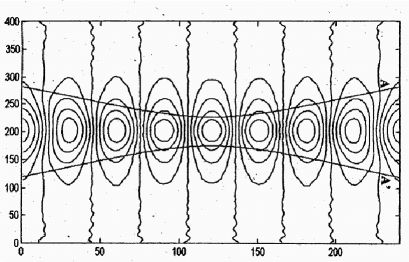
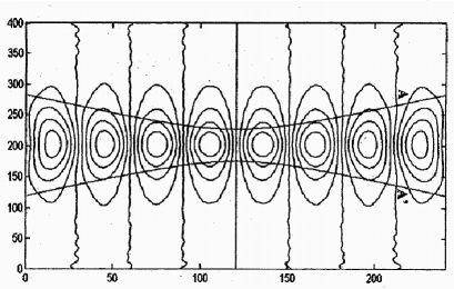
The geometry of Marcatili’s tapers can eventually be very complicated (e.g., see [8]). For our tests, however, we chose a simple shape, to avoid the danger that geometrical features could hide the basic physics we were trying to clarify. The results reported here refer to a single-mode taper whose graded-index core region is delimited by the two branches of a hyperbola (labeled A and A’ in Figs. 1 and 2), and has a mirror symmetry with respect to its waist. This is a “superlinear” taper, according to the terminology of [1], with an index distribution (see again [1])
| (1) |
where and are the elliptical coordinates, in the plane of Figs. 1 and 2. Fig. 1 refers to a standing wave of even symmetry with respect to the waist plane, Fig. 2 to a standing wave of odd symmetry. The closed lines are constant-amplitude plots. We see that they are essentially elliptical, so they agree very well with the predictions of [1].
As mentioned briefly in the Introduction, these results were generated using an extended BPM, which deserves a short description. In fact, it is well known that the standard BPM codes are suitable to track only traveling waves, as they neglect backward waves. Our code (using a Pade’s operator of order (5,5)) also generates a traveling wave, and its direction of propagation is inverted whenever the wave reaches one of the taper ends. In order to generate single-mode standing waves, each reflection should take place on a surface whose shape matches exactly that of the wave front. This is very difficult to implement numerically, but the problem can be circumvented, letting each reflection take place on a phase-conjugation flat mirror. Our code calculates then, at each point in the taper, the sum of the forward and backward fields, and stops when the difference between two iterations is below a given threshold.
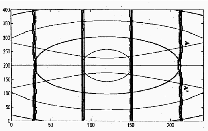
Figs. 3 and 4 refer to a through-flowing wave. The almost horizontal dark lines in Fig. 3 are its phase fronts. They are drastically different from those predicted by the analytical theory in [1], which are exemplified in the same figure as a set of confocal ellipses. Note that the through-flowing wave has been studied numerically in two ways. One was simply to launch a suitable transverse field distribution, and track it down the taper with a standard BPM code. The other one was to calculate the linear combination (with coefficients and ) of the even and odd standing waves shown in Figs. 1 and 2. The results obtained in these two ways were indistinguishable one from the other. This proves that indeed through-flowing waves are drastically different from standing ones. In particular, as we said in the Introduction, they keep clear from any paradox connected with energy conservation.
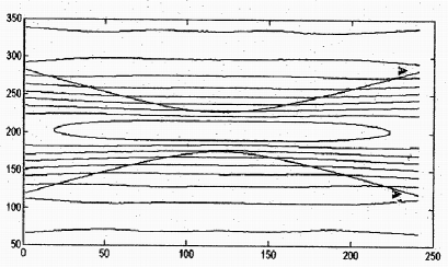
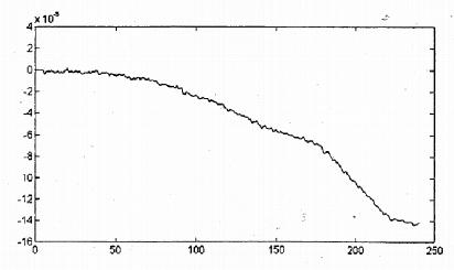
Fig. 4 shows a field amplitude contour plot for the same through-flowing wave as in Fig. 3. It indicates that propagation through the taper is indeed almost adiabatic. Therefore, as anticipated in the Introduction, insertion losses of Marcatili’s tapers are very low (at least as long as the length to width ratio is not too small), although they are not strictly zero. As a typical example, for a total taper length of , a waist width of and an initial-final width of , BPM calculations yield that the lost power fraction is . A typical plot of power vs. distance along a taper with these features is shown in Fig. 5.
IV Theoretical discussion.
For the sake of clarity, let us restrict ourselves to the case of two-dimensional tapers, like those of the previous section, where the geometry and the index distribution are independent of the coordinate, orthogonal to the plane of the figures. However, our conclusions will apply to 3-D structure also.
The index distributions found in the corner-stone paper [1] are such that the TE modes (electric field parallel to ) satisfy rigorously a wave equation which can be solved by separation of variables. Obviously, the same equation is satisfied rigorously by the transverse component of the magnetic field.
However, in general two solutions of these two wave equations which are identical, except for a proportionality constant, do not satisfy Maxwell’s equations in that structure. This is very easy to show, for example, for the case which was called “linear taper” in [1], namely, a wedged-shape region with a suitable index distribution, where a guided mode propagates in the radial direction. The claim [1] that the dependence of on the radial coordinate is expressed by a Hankel function of imaginary order , related to other features of the taper, is perfectly legitimate. However, one cannot extrapolate from it that the same is true for the magnetic field. In fact, calculating the curl of the electric field we find that the azimuthal component of the magnetic field is proportional to the first derivative of the Hankel function, which is never proportional to the function itself. The same is true for the Mathieu function of the fourth kind, which satisfy the wave equation in the coordinate system which fits the superlinear taper of the previous Section. This entails a drastic difference with plane waves, and with guided modes in uniform waveguides, where the derivative of the exponential function that describes the propagation of the electric field is proportional to the function itself. In the cases at hand, the concept of wave impedance becomes ill-grounded. In fact, the electric field and the transverse magnetic field have identical dependencies on the transverse coordinate, so that their ratio is constant over each wavefront, but they are different functions of the longitudinal coordinate, as if the ‘wave impedance’ were not constant at all along the wave path. This indicates why it is very risky, in the case at hand, to make general claims on the Poynting vector starting from the spatial distribution of only the electric field. To strengthen our point, let us prove explicitly that it is not self-consistent to claim that a purely traveling TE wave, whose radial dependence is expressed by a Hankel function of imaginary order, , can propagate along a linear taper. As we just said, for such a wave is proportional to , is proportional to , so the radial component of the Poynting vector is proportional to . In a purely traveling wave there is no reactive power in the direction of propagation. Combining with what we just said, it is easy to see that this would imply along the (radial) direction of propagation, a requirement that is not satisfied by Hankel functions. (Note, once more, that it is satisfied by exponential functions). Therefore, any wave along a linear taper whose radial dependence is expressed as a Hankel function must be at least a partially standing wave. A through-flowing wave, if it exists, must behave in a different way.
Finally, let us address briefly the case of Gaussian beams in free space. It was pointed out in [2] that they behave essentially in the same way as the devices we discussed above. There is still something to add to the discussion of [2]. Assume that the electric field of an electromagnetic wave has the classical features of a Gaussian beam (see, e.g., [9]). Then, Maxwell’s equations show that the phase fronts of the magnetic field are not the same as those of the electric field, neither on the waist plane nor far from it. Hence, the Poynting vector is not trivially proportional to the square of the electric field. This entails the presence of a reactive power (never accounted for in the classical classroom explanations of Gaussian beams), and an active power flow which is not always along the lines orthogonal to the electric field phase fronts. Once again, a through-flowing beam, resulting from two superimposed standing waves of opposite parities, is different from the parent waves, and the difference is maximum on the symmetry plane, i.e. at the beam waist. Due to time and space limits, the details of this discussion must be left out of this presentation, and will be published elsewhere [10].
V Conclusion.
We tried to shed new light on an old problem, namely, whether the idea of a guided mode traveling without any loss through a dielectric taper can be sustained without running into any physical paradox. Our numerical results, obtained with an extended BPM technique, have fully reconfirmed what was stated in [2]: in Marcatili’s tapers, standing waves have the basic features outlined in [1], but through-flowing waves do not. This prevents them from running into a paradox, but on the other hand entails some loss, although very small indeed. Next, we have provided an explanation for the unexpected and puzzling result, a drastic difference between standing and through-flowing waves in the same structures. The source of these “surprise” is within Maxwell’s equations.
It was pointed out in [2] that some of the problems discussed here with reference to Marcatili’s tapers apply to Gaussian beams in free space as well.
REFERENCES
- [1] E.A.J. Marcatili, “Dielectric tapers with curved axes and no loss”, IEEE J. Quant. Electron., vol. 21, pp. 307-314, Apr. 1985.
- [2] E.A.J. Marcatili and C.G. Someda, “Gaussian beams are fundamentally different from free-space modes”, IEEE J. Quant. Electron., vol. 231, pp. 164-167, Feb. 1987.
- [3] O. Mtomi, K. Kasaya and H. Miyazawa, “Design of a single-mode tapered waveguide for low-loss chip-to-fiber coupling”, IEEE J. Quant. Electron., vol. 30, pp. 1787-1793, Aug. 1994.
- [4] I. Mansour and C.G. Someda, “Numerical optimization procedure for low-loss sharp bends in MgO co-doped waveguides”, IEEE Photon. Technol. Lett., vol 7, pp. 81-83, Jan. 1995.
- [5] C. Vassallo, “Analysis of tapered mode transformers for semiconductor optical amplifiers”, Optical and Quantum Electron., vol. 26, pp. 235-248, 1994.
- [6] M.-L. Wu, P.-L. Fan, J.-M. Hsu and C.-T. Lee, “Design of ideal structures for lossless bends in optical waveguides by conformal mapping”, IEEE J. Lightwave Technol., vol. 14, pp. 2604-2614, Nov. 1996.
- [7] C.-T. Lee, M.-L. Wu, L.-G. Sheu, P.-L. Fan and J.-M. Hsu, “Design and analysis of completely adiabatic tapered waveguides by conformal mapping“, IEEE J. Lightwave Technol., vol. 15, pp. 403-410, Feb. 1997.
- [8] J.I. Sakai and E.A.J. Marcatili, “Lossless dielectric tapers with three-dimensional geometry”, IEEE J. Lightwave Technol., vol. 9, pp. 386-393, Mar. 1991.
- [9] C.G. Someda, “Electromagnetic Waves”, Chapman & Hall, London, 1998, pp. 165-171.
- [10] A. D. Capobianco, M. Midrio and C. G. Someda, “TE and TM Gaussian beams in a homogeneous medium”, to be published.