Measurements of the radiation hardness of selected scintillating and light guide fiber materials
Abstract
Radiation hardness studies of KURARAY SCSF-78M scintillating fibers and clear fibers from KURARAY and pol.hi.tech. performed under different dose rate conditions in proton and electron beams are summarized. For high dose rates in-situ measurements of the fiber light output were done. During several months after irradiation all fibers were measured concerning light emission and transparency.
Fibers irradiated at high rates to about 1 Mrad are clearly damaged but recover within a few hours up to several weeks. Using smaller rates up to the same integral dose a decrease of the light output of scintillating fibers of up to 30 can not be excluded. Clear fibers seem to be uneffected up to 400 krad. No significant influence of fiber coverage and atmosphere during irradiation was found.
,
***corresponding author, phone: +49 33762
77235, Fax: +49 33762 77330,
e-mail:
baehr@ifh.de,
,
††thanks: on leave from High Energy Physics Institute, Tbilisi
State
University, Georgia
1 Introduction
Recently [1]-[3] a fiber detector was developed as an alternative solution for the inner tracker of the HERA-B experiment [4]. With an accelerator cycle of 96 nsec and four events per cycle with a charged multiplicity of about 200 the detector modules have to work several years under an estimated integral dose per year in the inner tracker region of about 1 Mrad.
The light produced by particles crossing the scintillating fibers of the detector is transported by 3 m long light guide fibers to 64 channel multianode photomultipliers Hamamatsu R5900-M64111 Hamamatsu Photonics K.K., Electron tube division, 3124-5, Shimokanzo, Tokyooka Village, Iwatagun, Shizuoka-ken, Japan available only with bialcali photocathodes. Best light output and long term stability were obtained for KURARAY222KURARAY Co.Ltd., Nikonbashi, Chuo-ku, Tokyo 103, Japan scintillating double clad fibers SCSF-78M and clear double clad fibers from KURARAY and pol.hi.tech.333pol.hi.tech., s.r.l., S.P. Turanense, 67061 Carsoli(AQ), Italy. The corresponding radiation hardness studies were performed with high dose rates in 70 MeV proton and 2 MeV electron beams of the Hahn-Meitner Institute Berlin [1],[3],[5],[6] and photons from a 60Co source [2]. In the first case in-situ measurements of the light output even with spectral resolution were possible.
In the past there were several arguments [7]-[9] that the presence of oxygen during and after the irradiation may be important for the observed damage. In this case also the dose rate may influence the final result because diffusion processes are time dependent.
Our results from high dose rates using charged particle beams will be summarized below and compared to new data from low dose rate exposures of the same materials. The new tests were performed in air and nitrogen atmosphere with glued and non-glued scintillating fibers and compared with non-irradiated test samples.
2 Experimental conditions
2.1 Fiber samples
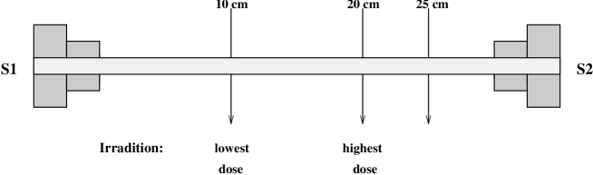
The fiber samples for proton and electron irradiation have the same global structure as shown in Fig. 1. For high rate irradiation 44 fibers of 0.48 mm diameter were glued together resulting in a cross section of about 22 mm2. The samples for electron low dose rate irradiation consist of a fiber arrangement of 17 fibers of the same diameter forming a fiber road in the later detector. Coupling pieces are mounted at both ends of the 30 cm long samples in which the ends of the fibers are inserted, glued and polished. This allows an optical coupling to light guides or photomultipliers with light losses of less than 10 %. The fiber samples are mechanically stabilized by two brass rods of 3 mm diameter.
For low dose rate electron irradiation there were two types of samples. The first type is fully glued to shield the fibers from the gaseous environment, whereas the second type is mounted using a minimum of glue in thin strips near the connectors in order to allow the gaseous atmosphere to have contact to the fiber material.
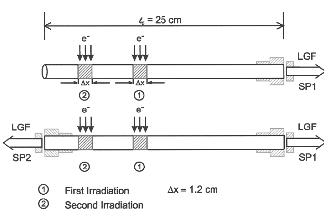
For the in-situ measurements single fibers were coupled at one or both ends to glass fibers which transport the light to the corresponding spectrometers (see Fig. 2).
2.2 Irradiation setup
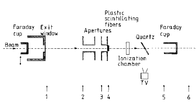
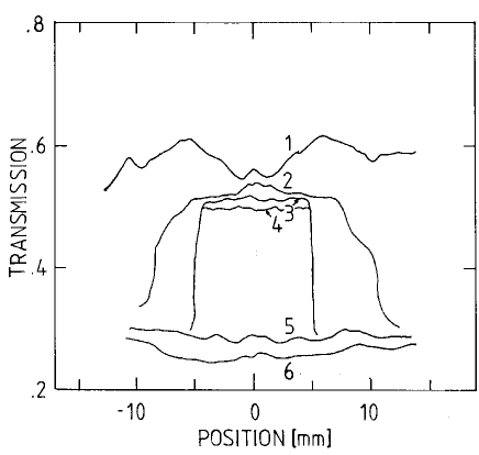
A schematic view of the irradiation setup in the proton and electron beams is given in Fig. 3. For electron irradiation the beam was extracted from the vacuum system through a window of 100 m thick Aluminium and 40 m Inconel. A metallic aperture of 312 mm2 was used for beam profile definition. In the case of the proton irradiation the beam was extracted through a 7 m thick Tantalum foil. The beam size and the emittance angle were limited by two PMMA (polymethyle methacrylate) apertures. The total range of protons in fiber material is about 39 mm which is checked by the profile of the colour changes in the PMMA aperture during the irradiation. The spot size and position was additionally monitored by polyvinylalcohol (PVA) methylene blue plastic detector foils [10]. The dye is radiation sensitive and its degradation yield is proportional to the irradiated particle fluence. The degradation of the dye in the foil has been determined by UV-VIS-spectroscopy. A typical result of such beam homogeneity control for proton irradiation is depicted in Fig. 4. The higher the transparency the higher was the irradiation dose in the given area. At positions 1, 2 a high radiation level with low restriction in the field distribution is registrated. The profile created by the plastic apertures is given by curve 3 and 4. A low non-structured irradiation level is characterized by curves 5 and 6.
For the in-situ registration of beam excited scintillation spectra fiber optic PC-plug-in spectrometers (Ocean Optics444Ocean Optics Inc., 380 Main Street, Dunedin, FL34698, USA) were used. They were placed outdoors of the cave in order to suppress the high radiation background using 22 m long light-guiding glass fibers . A detailed description of the used experimental setups in both cases can be found in [5].
The proton irradiation was performed quasi point-like at two points along the sample with a dose of 1 Mrad at 20 cm and of 0.1 Mrad at 10 cm respectively within a few minutes. The dose rate was about 30 Mrad/h. The irradiation of short areas of the samples gave the possibility to separate the damage of scintillator and optical matrix.
The same irradiation procedure was applied for in-situ measurements of radiation damage using a corresponding electron beam.
High current irradiations were only carried out under ambient atmosphere using cooling by a powerful fan. The temperature rise during the irradiation could be neglected [5].
A new series of tests has been performed irradiating the fiber
material with a relatively low dose rate of 2 MeV electrons to
approximate the later experimental conditions. A dose of about 1 Mrad
was applied during five periods within about nine weeks.
The particle flux was monitored by a
matrix of Faraday cups. The distance between scatter foil and sample
plane was about 1.5 m.
In this case the samples were kept
either in air or in nitrogen atmosphere.
2.3 Measurement procedure
In-situ registration of scintillation spectra first described in [11] was performed for the beam excited regions 1 and 2 (see fig. 2). The spectra were measured during the whole irradiation time in the first irradiated region 1 of fibers and after that in the second region 2 under influence of high absorption in the presumably predamaged region 1 in order to determine the change of the absorption coefficient during the irradiation. Between irradiation procedure 1 and 2 a preparation time of a few minutes was necessary. The beam excited scintillation spectrum served in the second case as changeable light source for absorption measurements in a limited spectral region.
For recovery measurements in the laboratory a few hours after
irradiation the optical excitation was realized by a high pressure
Hg-lamp at = 365 nm
.
In addition to the in-situ measurements which used single fiber
samples and UV-excitation for the measurement in the laboratory
investigations were done using multi-fiber bundles.
The irradiated multi-fiber samples (see section 2.1) were evaluated using a source. The fiber sample was mounted within a source
collimator slit. The light signal was
measured using a Philips555Philips Photonique, Av. Roger
Roacier, B.P. 520, F-19106 Brive, France XP 2020
photomultiplier and analyzed by an
Analog-to-digital converter (ADC). The ADC was triggered
by a threefold coincidence of signals coming from a 5 mm thick
plastic scintillator mounted behind the fibers using two Philips XP 1911 photomultipliers for readout and from a second photomultiplier
XP 2020 coupled to the second coupling piece of the fiber sample. The
light output measurement was performed before and after
irradiation. In addition the light output of the
non-irradiated scintillator reference samples and
light attenuation of the light guide
reference samples were regularily measured
to minimize systematic errors.
3 Results
From in-situ observations of proton and electron excited spectra
no remarkable difference could be found [6]. Consequently, we report here representative
results for both charge carrier excited spectra.
As described in [5], [6]
all in-situ measured spectra show a two stage decay of the
scintillating light intensity in dependence on the energy dissipation
(or irradiation time).
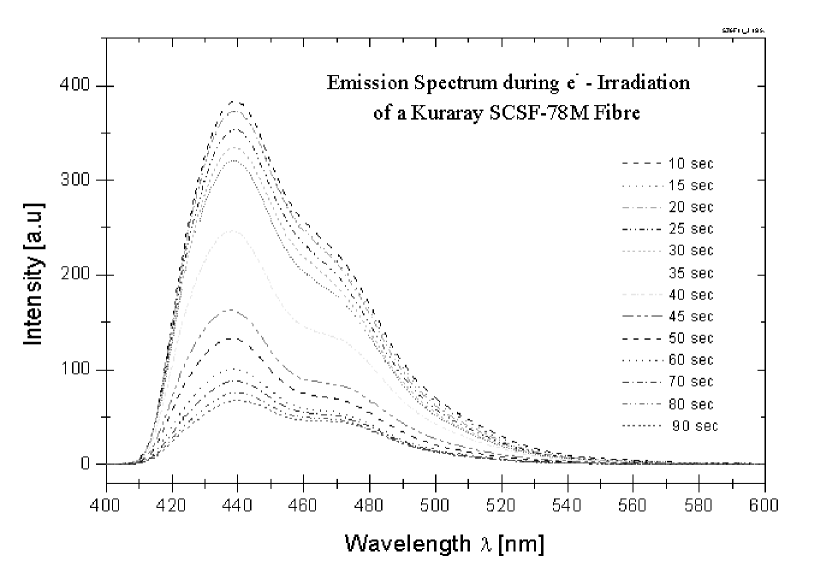
In Fig.5 a typical degradation process for an electron excited
fiber is presented with the wavelength as parameter. At the beginning
of the irradiation a similar time constant for all wavelengths can be
observed. A faster decay appears for
higher energy dose values of about 1 Mrad in dependence on different
wavelengths of emission spectra. The short-wave emission shows the fastest
degradation in time (see also Fig. 2 in [5]).
A recovery of the damaged fibers could be observed already during the in-situ measurements. A considerable increase in light output was observed several times during the irradiation procedure after switching off the beam for only three minutes (see Fig. 3 in [5]).
Exciting the same fibers by UV-light in the laboratory a few hours after irradiation a long term recovery was measured. After 40 hours a SCSF-78M fiber irradiated to 8.1 Mrad showed 90 of the light output with respect to pre-irradiation (Fig.4 in [5]). This process seems however to depend on the fiber material and the integral dose (compare Fig.2 in [6]).
The kind of excitation seems to be of particular importance for the measured fiber light output. This will influence also the observed recovery after irradiation and may explain the corresponding different time constants for in-situ measurements and UV-excitation.
In a real experiment the scintillation light in fibers will be produced by crossing charged particles. Therefore the multi-fiber test samples were exposed to electrons from a Ru-source before and after beam irradiation to measure light output and transmission. Indeed a different behaviour was found. As described in [1],[3] the strongest damage was observed only about 30 hours after irradiation with a dose of 1 Mrad for both light emission and transparency with a complete recovery after two days (see Fig. 4 of [3]).
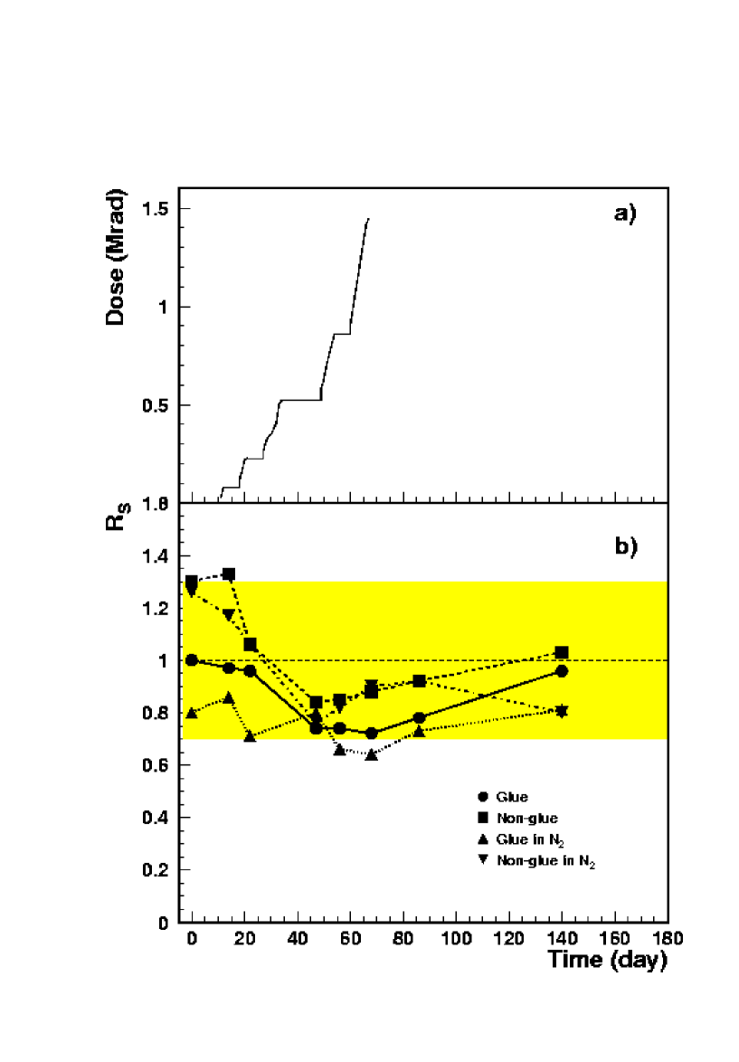
A dose of 1 Mrad, expected for the inner tracker of the HERA-B experiment within one year, was placed to the above test samples within a few minutes. This may have influenced the observed results in an inadmissible way in particular if oxygen diffusion is important for damage and recovery. To be closer to the experimental conditions the irradiation of scintillator and light guide samples was performed up to a dose of 1.4 Mrad within 70 days. Half of the fiber samples were covered by glue. The irradiation was done in air and in nitrogen atmosphere. The results are displayed in Figs. 6 and 7.
Measurements going on for about half a year, using many times the same samples, are difficult to perform keeping systematical errors small due to some instability of the setup in time and mechanical damages of the fragile samples. To minimize those effects, non-irradiated samples were measured every time in addition. All results are presented as ratios of irradiated to non-irradiated fibers RS and RL for scintillators and light guides, respectively. The maximum errors of these ratios have been estimated to be about 30 including effects which may arise from sample production.
How the irradiation was going on in time is demonstrated in Fig. 6a. The corresponding damage and recovery of four fiber samples is shown in fig 6b. No effect could be observed outside the 30 error band. Neglecting the measurement errors and relying on the pre-irradiation data points some damage may have happened up to the maximum dose followed by a long term recovery. The damage seems to be smaller for glued fibers in particular in nitrogen atmosphere. Non-glued fibers seem to recover only partly.
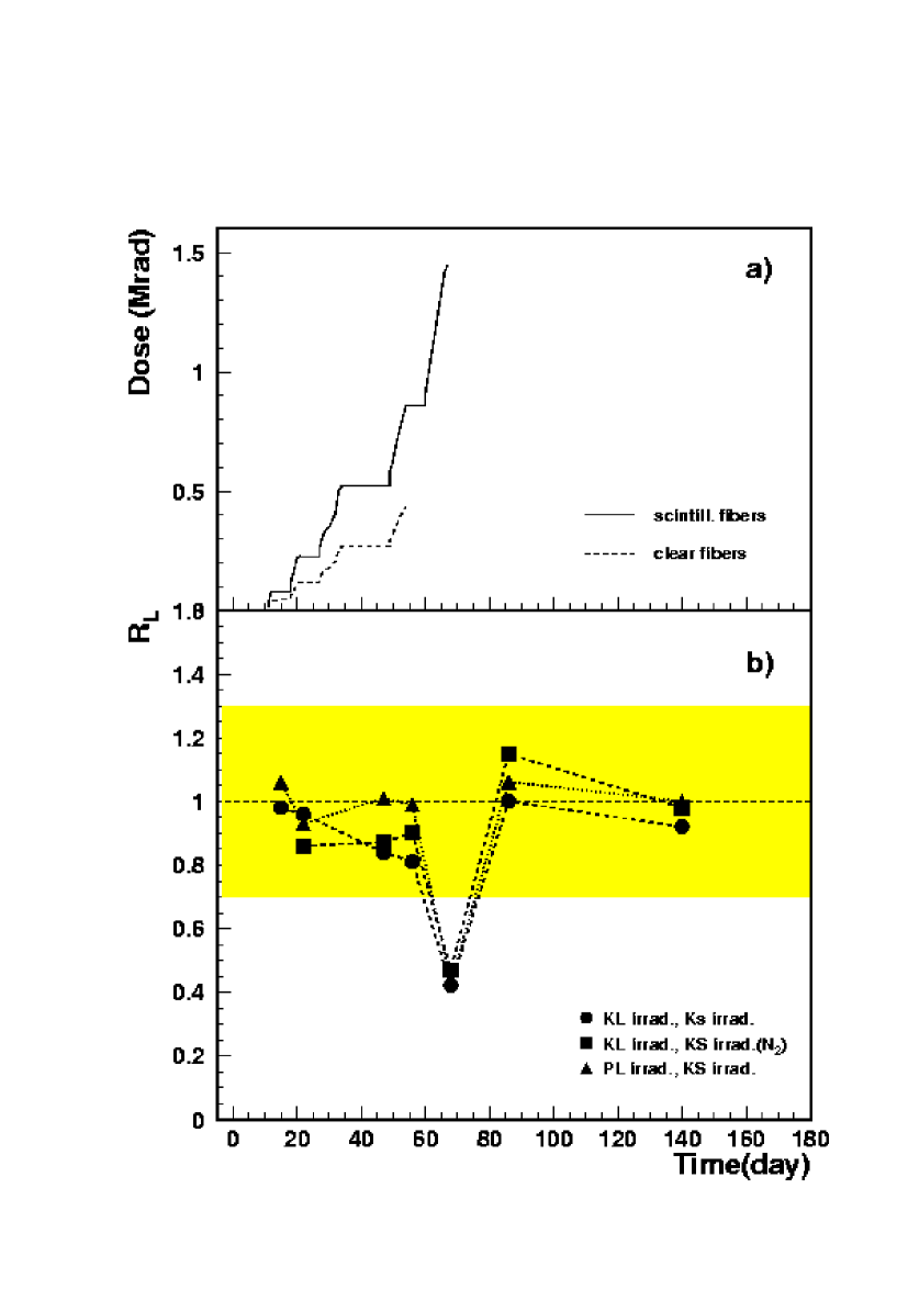
From Fig. 7a it can be seen that clear fibers were only irradiated up to a dose of 400 krad. For all measurements they were coupled to scintillating fibers which were excited by electrons from a Ru-source. Also here a maximum error of 30 has to be kept in mind for the ratio RL of irradiated to totally non-irradiated (clear plus scintillating) fibers shown in Fig 7b. Neglecting the error band no damage is seen for the clear fiber irradiation itself. However irradiating the scintillator to more than 1 Mrad caused a decrease of the light output from a coupled clear fiber to more than one half, i.e. more than observed for the scintillating sample alone. After two weeks complete recovery was found. The behaviour is the same for KURARAY and pol.hi.tech. clear fibers in air and nitrogen.
4 Summary
Several radiation hardness tests were performed for KURARAY scintillating fibers SCSF-78M and clear fibers from KURARAY and pol.hi.tech. Using high current proton and electron beams the irradiation was performed both with very high and low dose rates.
In-situ observations demonstrated a strong damage of scintillating fibers for high dose rate exposures. Both light emission and transparency were decreased down to 20 for 1 Mrad. Short and long time recovery effects followed the irradiation.
For low dose rate conditions closer to a later experiment, a 30 decrease of scintillating fiber light output could not be excluded recovering after three weeks. No significant influence of the fiber coverage and the atmosphere during irradiation was found.
Clear fibers are apparently not damaged for doses up to 400 krad. Coupled to irradiated scintillating fibers the effective damage of the system seems to increase.
Acknowledgement
The fiber irradiation tests were possible only due to the kind support of the Hahn-Meitner-Institute Berlin. In particular we want to thank the ISL accelerator team.
References
- [1] Aschenauer E.C. et al., Preprint DESY 97-174(1997)
- [2] Dreis B., et al., preprint DESY 98-049 (1998)
- [3] Aschenauer E.C. et al., NIM A424,(1999) 459
- [4] Lohse,T. et al., HERA-B Technical Proposal, DESY-PRC 94/02 (1994)
- [5] Klose H.A. et al., NIM B135, 555(1998)
- [6] Klose H.A. et al., Proc. Fourth Int. Conf. Radecs 97, 4,461(1998)
- [7] Zorn C. et al., Nucl. Phys. B (Proc.Suppl.) 32, 369 (1993)
- [8] Busjan W., Thesis, DESY F35D-97-09 (1997)
- [9] Hamada M. M. et al., NIM A422,(1999) 148
- [10] Chung W.H. and Miller A., Nucl.Technol.(Am. Nucl. Soc.) 1̱06, 261(1994)
- [11] Klose H.A. et al., NIM B116, 235(1996)
Figure captions
Fig. 1 : Sketch of a multifiber test sample with indication of the
irradiation and measurement positions. The signal is measured via
coupling piece S1, the coupling piece S2 is used for the extraction of
a trigger signal.
Fig. 2 : Fiber sample for in-situ measurements with irradiation
position and connections of fibers to spectrometers. LGF: Light guide
fiber, SP1, SP2: Coupling to spectrometers 1, 2.
Fig. 3 : Irradiation setup of the high dose rate proton and electron
irradiation. The arrows give the positions of plastic detectors for
beam profile measurement according to Fig. 4.
Fig. 4 : Beam profile measured using polyvinylalcohol methylene blue
plastic detector. The figures belonging to each curve correspond to
the arrows in Fig. 3 giving the positions of such plastic films in the
irradiation setup: 1 - behind the exit window, 2- before the aperture
1, 3 - between aperture 1 and 2, 4- behind aperture 2, 5 - before the
Faraday cup, 6 - behind the Faraday cup.
Fig. 5 : In-situ measurement of the emission spectra of a
scintillating fiber excited by high dose rate electron irradiation in
dependence on the irradiation time in seconds.
Fig. 6 : a.) Time dependence of irradiation dose for scintillating
fibers,
b.) ratio RS of light output from irradiated to non-irradiated
scintillating fiber samples in dependence on measurement time with
respect to the first irradiation.
Fig. 7 : a.) Time dependence of irradiation dose for scintillating
fibers and light guides, b.) ratio RL of light output from irradiated
to non-irradiated clear and scintillating fiber samples in dependence
of the measurement time with respect to the first irradiation.
KL: Light guide fiber from KURARAY, KS: Scintillating fiber from
KURARAY, PL: Light guide fiber from pol.hi.tech.