Removal of surface plasmon polariton eigenmodes degeneracy
Abstract
The effect of the tilt angle of metal film on the transmissivity of subwavelength holes in optically thick metal film is investigated. The transmission efficiency is found can be highly dependent on the tilt angle. It is also found that when the input photons are polarized not along the eigenmode directions of surface plasmon polariton, a birefringent phenomenon is observed when the array with periodic of subwavelength holes is tilted. Linear polarization states can be changed to elliptical polarization states and a phase can be added between two eigenmodes. The phase is changed with the tilt angle. A model based on surface plasmon polariton eigenmodes degeneracy is presented to explain these experimental results.
1 Introduction
Since it was first reported in 19981 , the extraordinary optical transmission (EOT) through periodic arrays of subwavelength holes has attracted much attention owing to its fundamental implications and its technological potential. Generally, it is believed that metal surface plays a crucial role and the phenomenon is mediated by surface plasmon polaritons (SPPs) and there is a process of transform photon to surface plasmon polariton and back to photon4 ; crucial ; ebbesen5 . The polarization of the incident light determines the mode of excited surface plasmon which is also related to the periodic structure. This phenomenon can be used in various applications, for example, sensors, opto electronic device, etcwilliams ; brolo ; nahata ; luo ; shinada .
In 2002, E. Altewischer et al. alt first showed that polarization entanglement of photon pairs can be preserved when they respectively travel through a hole array. Therefore, the macroscopic surface plasmon polarizations, a collective excitation wave involving typically free electrons propagating at the surface of conducting matter, have a true quantum nature. After that, polarization properties of EOT were investigated in many works. For example, strong polarization dependence was observed in EOT of elliptical nanoholesElli04 ; Gordon04 ; polarization tomography of metallic nanohole arrays has been done recentlyAltew05 ; Altew052 ; and state of polarization was also studied and modeled as a function of angular bandwidth in EOTAltew053 . However, the increasing use of EOT requires further understanding of the phenomenon.
For the manipulation of light at a subwavelength scale with periodic arrays of holes, two ingredients exist: shape and periodicity4 ; crucial ; ebbesen5 ; klein ; elliott ; Ruan ; sarra . The mode of excited surface plasmon polariton is related to the periodic structure and the polarization of the incident light. Usually, the surface plasmon polariton eigenmodes are degenerate due to the symmetry of the hole array and the polarization of photon can be preserved in the EOT processalt ; Altew05 . In a recent paper, splitting of degenerate surface plasmon polariton eigenmodes was observedLin . Then, is there any influence on the polarization of transmitted photons if the degeneracy of surface plasmon polariton eigenmodes are removed? A feasible method to remove the degeneracy is tilting the hole array. In our work, it was found that photons with the same linear polarization can be transformed into various elliptical polarization states if the hole array was tilted. In detail, if the photons were polarized along the eigenmode directions of surface plasmon polaritons, the polarization states were not changed. Otherwise, a phase was generated between different surface plasmon polaritons, as in a birefringent process. A linear polarization state was changed to . The phase was varied with the tilt angle . This phenomenon might come from the removal of degeneracy of surface plasmon polariton eigenmodes.
2 Experimental results
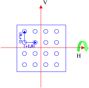

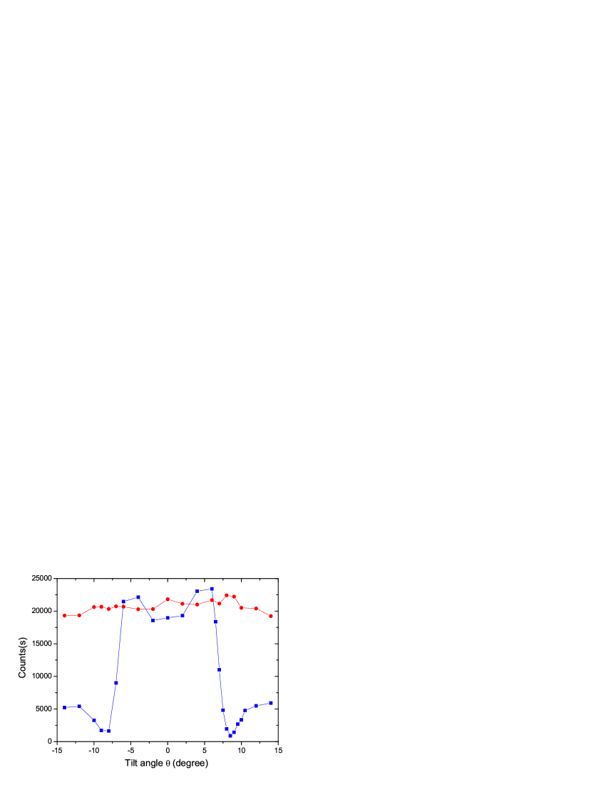
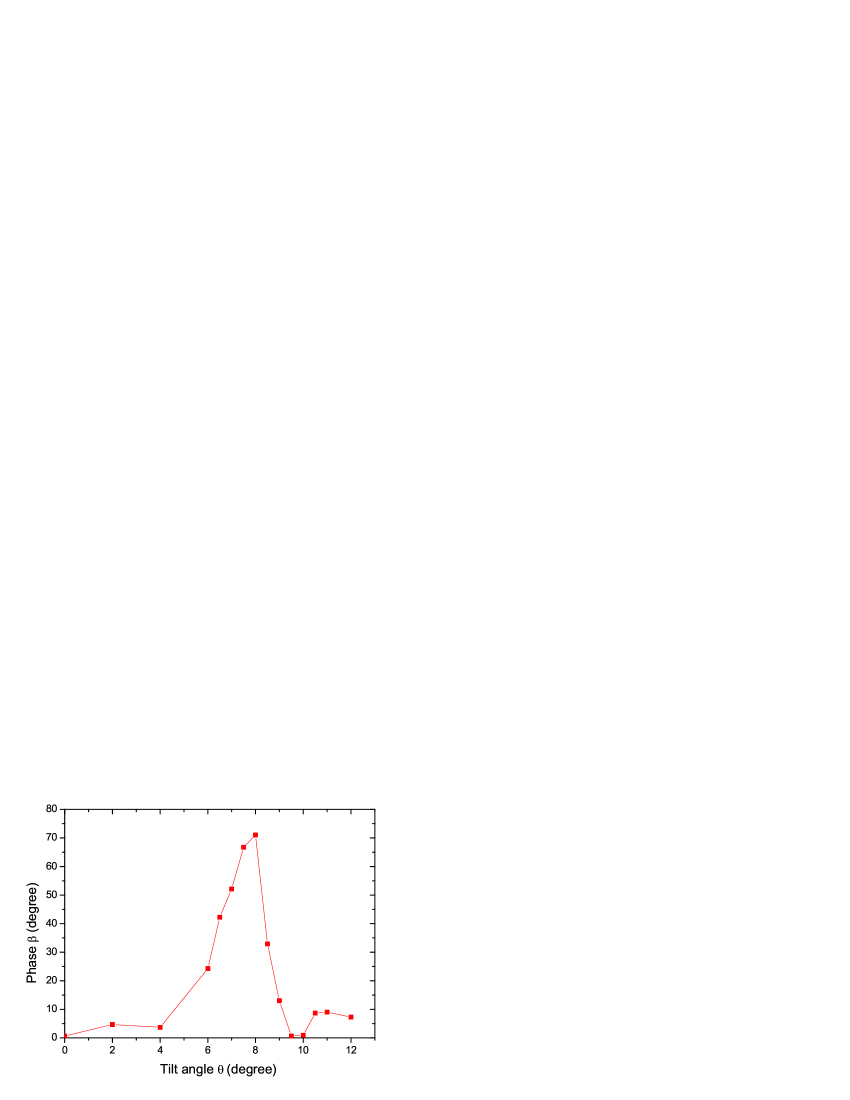
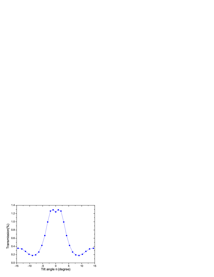
Fig. 1 shows the sketch map of our hole array. It is produced as follows: after subsequently evaporating a - titanium bonding layer and a - gold layer onto a --thick silica glass substrate, a Electron Beam Lithography System (EBL, Raith 150 of Raith Co.) is used to produce cylindrical holes ( diameter) arranged as a square lattice ( period). The total area of the hole array is . The arrow indicates the tilting direction. Transmission spectra of the hole arrays for vertical polarized photons was shown in Fig. 2. The dashed vertical line indicates the wavelength of used in our experiment. The transmission efficiency of the metal plate at is about , which is much larger than the value of obtained from classical theoryBethe .
In experiment, white light from a stabilized tungsten-halogen source passed though single mode fiber and filter (center wavelength 702 nm) to generate 702nm wavelength photons. Polarization of input light was controlled by a polarizer, a HWP (half wave plate, 702nm) and a QWP (quarter wave plate, 702nm). The hole array was set between two lenses of focal length, so that the light was normally incident on the hole array with a cross sectional diameter about and covered hundreds of holes. Symmetrically, a QWP, a HWP and a polarizer were combined to analyze the polarization of transmitted photons. Silicon avalanche photodiode (APD) photon counter was used to record counts(We use neutral density filter to reduce the intensity of input light).
For our sample, photons with wavelength will excite the surface plasmon polariton eigenmodes and (see Fig. 1). The hole array was tilted in the vertical direction with tilt angle as shown in Fig. 1. First, transmission efficiencies of photons in horizontal and vertical polarization were measured. For photons in horizontal polarization, the transmission efficiency was kept constant, while for photons in vertical polarization, the transmission efficiency was changed with the tilt angle ( see Fig. 3). Further, polarization state tomography method was used to analyze the influence of tilt angle on the polarization properties of the hole array. It was found that for photons which were polarized along the eigenmode directions (here horizontal and vertical), the polarization of transmitted photons were not changed. When tilt angle was changed from to , the fidelities between the polarization states of input and output photons for horizontal polarized photons were all higher than , and for vertical polarized photons all higher than . It was interesting that even the transmission efficiency of vertical polarized photons was varied with , the polarization state was not changed.
Then photons in polarization state illuminated the hole array and the polarization of transmitted photons were analyzed using polarization state tomography. We found that even the input state was a linear polarization state, the output state was changed to an elliptical polarization state . A phase was generated in the EOT process when the metal plate was tilted. The relation between and tilt angle is given in Fig. 4. The similar results were also observed when the input state was .
3 Modeling
A simple model was given below to explain the experimental results. As we know, the interaction of the incident light with surface plasmon polariton is made allowed by coupling through the grating momentum and obeys conservation of momentum
| (1) |
where is the surface plasmon wave vector, is the component of the incident wave vector that lies in the plane of the sample, and are the reciprocal lattice vectors for a square lattice with , and i, j are integers. For our sample, surface plasmon polariton eigenmodes and are always degenerate when the hole array is tilted vertically. If the input state is , the whole EOT process can be described briefly as:
| (2) |
Obviously, there will be no influence on the transmission of horizontal polarized photons(including the transmission efficiency and polarization) as we observed. While in vertical direction, due to the nonzero . The degeneracy between surface plasmon polariton eigenmodes and is removed. In this case, momentum of the surface plasmon polariton, photons and structure were also quasi-conserved. The reason was that the hole diameter was , which can not be neglected comparing with the periodicity . When the photons in vertical polarization illuminate the hole array, two different surface plasmon polariton eigenmodes are excited. The transmission peaks corresponding these two eigenmodes will move away in opposite direction(see Fig .3 of Ref[22]). Since the transmitted photons were eradiated from the two surface plasmon polariton eigenmodes, the whole transmission efficiency was the sum of the two cases. This definitely influence the transmission efficiency of photons in 702nm wavelength as shown in Fig. 3. In the theoretical calculation, the whole transmission of Fig. 2 was divided into two equal parts( mode and mode), the two parts moved to short wave and long wave directions respectively(see Fig .3 of Ref[22]) when the metal plate was tilted. A simple addition of two moved transmission peaks was given in Fig 5, while in the calculation we supposed that the shape of the transmission peaks was not changed for the sake of simplification. It had a similar curve with the experimental data.
Further, since , a phase is generated between these two different photon to surface plasmon polariton and back to photon process:
| (3) |
So if the input state is , the output state becomes . Of course, phase was correlated with the difference between and (or ), which was determined by the rotation angle . will increase for larger tilt angle in a small range. While when became bigger, the conservation of momentum was destroyed. The analysis above will be not appropriate. Fig. 4 gives the relation between phase and tilt angle . The shape of the line agreed with our prediction.
4 Conclusion and discussion
In conclusion, we found that when the hole array was tilted in the EOT process, not only the transmission spectra was influenced, but also a birefringent phenomenon appeared. Linear polarization state can be changed to elliptical one: . Since the phase can be controlled by changing the tilt angle , we can modulate the birefringent phenomenon in EOT process. Using a simple model based on surface plasmon polarition, we briefly explained the experimental results, while further works are need to give a detailed explanation. Our results may give us more hints on the polarization properties of EOT.
This work was funded by the National Fundamental Research Program, National Nature Science Foundation of China (10604052), Program for New Century Excellent Talents in University, the Innovation Funds from Chinese Academy of Sciences and the Program of the Education Department of Anhui Province (Grant No.2006kj074A). Xi-Feng Ren also thanks for the China Postdoctoral Science Foundation (20060400205) and the K. C. Wong Education Foundation, Hong Kong.
References
- (1) T.W. Ebbesen, H. J. Lezec, H. F. Ghaemi, T. Thio, and P. A. Wolff, Nature 391, 667 (1998).
- (2) H. Raether, Surface Plasmons on Smooth and Rough Surfaces and on Gratings, Springer Tracts in Modern Physics, Springer, Berlin, 1988 Vol. 111.
- (3) D. E. Grupp, H. J. Lezec, T. W. Ebbesen, K. M. Pellerin, and Tineke Thio, Appl. Phys. Lett. 77 1569 (2000).
- (4) M. Moreno, F. J. Garc a-Vidal, H. J. Lezec, K. M. Pellerin, T. Thio, J. B. Pendry, and T. W. Ebbesen, Phys. Rev. Lett. 86, 1114 (2001).
- (5) S. M. Williams, K. R. Rodriguez, S. Teeters-Kennedy, A. D. Stafford, S. R. Bishop, U. K. Lincoln, and J. V. Coe, J. Phys. Chem. B. 108, 11833 (2004).
- (6) A. G. Brolo, R. Gordon, B. Leathem, and K. L. Kavanagh, Langmuir. 20, 4813 (2004).
- (7) A. Nahata, R. A. Linke, T. Ishi, and K. Ohashi, Opt. Lett. 28, 423 (2003).
- (8) X. Luo and T. Ishihara, Appl. Phys. Lett. 84, 4780 (2004).
- (9) S. Shinada, J. Hasijume and F. Koyama, Appl. Phys. Lett. 83, 836 (2003).
- (10) E. Altewischer, M. P. van Exter and J. P. Woerdman, Nature 418 304 (2002).
- (11) J. Elliott, I. I. Smolyaninov, N. I. Zheludev, and A. V. Zayats, Opt. Lett. 29, 1414 (2004).
- (12) R. Gordon, A. G. Brolo, A. McKinnon, A. Rajora, B. Leathem, and K. L. Kavanagh, Phys. Rev. Lett. 92, 037401 (2004).
- (13) E. Altewischer, C. Genet, M. P. van Exter, and J. P. Woerdman, Opt. Lett. 30, 90 (2005).
- (14) E. Altewischer, Y. C. Oei, M. P. van Exter, and J. P. Woerdman, Phys. Rev. A 72, 013817 (2005).
- (15) E. Altewischer, M. P. van Exter, and J. P. Woerdman, J. Opt. Soc. Am. B. 22, 1731 (2005).
- (16) K. J. Klein Koerkamp, S. Enoch, F. B. Segerink, N. F. van Hulst and L. Kuipers, Phys. Rev. Lett. 92 183901 (2004).
- (17) J. Elliott, I. I. Smolyaninov, N. I. Zheludev and A. V. Zayats, Phys. Rev. B 70, 233403 (2004).
- (18) Zhichao Ruan and Min Qiu, Phys. Rev. Lett. 96 233901 (2006).
- (19) M. Sarrazin, J. P. Vigneron, Opt. Commun. 240 89 (2001) .
- (20) Lin Pang, K. A. Tetz, and Y. Fainman, Appl. Phys. Lett. 90, 111103 (2007).
- (21) H. A. Bethe, Phys. Rev. 66, 182 (1944).
- (22) C. Genet, M. P. van Exter, and J. P. Woerdman, J. Opt. Soc. Am. A. 22, 998 (2005).