Refracting profiles and generalized holodiagrams
Abstract
The recently developed concept of refracting profiles and that of
refraction holodiagrams are combined so that the classical
Abramson holodiagrams can be generalized taking into account a
wider class of wave fronts and refraction at an interface,
whenever regions of caustics are avoided. These holodiagrams are
obtained as envelopes of specific families of Cartesian Ovals with
an appropriate parametrization. Classical and reflecting
holodiagrams are particular cases of this class. Several of the
properties of the classical holodiagrams are shared by their
richer generalized versions.
PACS:
42.40.-i, 42.40.Jv, 42.15.Dp.
keywords:
Refracting profiles; Focusing profiles; Holodiagrams, ,
1 Introduction
In 1969 and 1970, Abramson abramson1 ; abramson2 ; abramson3 ; abramson4 proposed the use of a diagram that condensed many useful properties of holographic registers, initially concerning the optimal use of available coherence length and the interpretation of the fringes obtained in holographic interferometry abramson5 ; abramson6 . It consisted in a family of ellipses showing the loci of equal optical path length between their common foci and with an adequate parameterization: consecutive ellipses differed in integer steps of half the wavelength in the optical path length. The foci represented a light emitting point source and an observation point. The chosen parameterization made interpretation of its cuts as Fresnel zone plates and its volumetric regions as Bragg gratings. Fermat s stationary phase principle was also built in and permitted elementary ray tracing. Numerous additional and non trivial uses have been found afterwards for that diagram, called Abramson holodiagram (HD). They include interferometry sensitivity evaluation, light-in flight registers, Doppler velocimetry, Bragg diffraction, interpretation of relativistic effects and several others.
The concept of Abramson holodiagram, originally developed to describe free propagation in an isotropic medium, has been broadened to include virtual sources rabal5 , refraction between two isotropic media rabal6 ; rabal7 , free propagation in birefringent media rabal8 and some geometrical aspects of spatial coherence rabal9 .
On the other hand, the concept of reflecting profiles criado10 ; criado11 has been developed to generate surfaces that modify a spherical wave front, giving place to another previously determined wave front or, conversely, to focus a predetermined wave front into a point. In a recent work criado12 we have proposed that the Holodiagram concept can be generalized with the aid of the reflecting profiles concept. A generalized holodiagram can then be constructed as a family of reflecting profiles with an adequate parametrization. It inherits several of the properties of other holodiagrams defined before.
Recently a method has been proposed to design suitable refracting profiles (interfaces between two media with different refractive index) for two different problems: to produce a given wave front from a single point source after refraction on it, and to focus a given wave front on a chosen point after refraction (see criado13 ). In the present paper, the refracting profile concept is included into the holodiagram construction, giving rise to the concept of generalized refracting holodiagram (GRHD), which includes all the (isotropic) holodiagrams previously developed.
The paper is organized as follows. In section 2 we use criado13 and construct two families of refracting profiles by using the optical properties of Cartesian ovals lockwood14 . Each profile is constructed as the envelope of a specific familiy of Cartesian ovals, and depends of a parameter that corresponds to half the value of the optical path between the foci of the family of Descartes ovals used in its construction.
In section 3 we use the two families of refracting profiles of section 2 to construct two kinds of generalized refracting holodiagrams: one when both source and image are real, and the other when the source is virtual (or the image is virtual). To this end we discretize the values of the parameter in multiples of half the wavelength employed for illumination.
In section 4 we give some illustrative examples. Also in this section we use the intersection of the surfaces of the GRHR with any glass plate surface to design diffraction gratings that work as generalized Fresnel zone plates. Finally we show how to use the refracting profiles to design lens that maps a predetermined wave front into another also predetermined wave front .
2 Refracting profiles

Given a wave front and a source point , it is possible to construct a family of refracting profiles parametrized by a non-negative real number , with the property of producing normal rays to after refracting the rays that emerge from at each profile. If light propagation direction is reversed, then the same family of profiles has the property of focusing the wave front in the point . From now on we suppose that the refracting profile separates two media with refractive indices and , being in the region of , and in the region of .
The construction of the profile for the wave front and the point proceeds (see criado13 ) by taking the envelope of a family of Descartes ovals of revolution , where has foci and , varies in and the parameter is such that is the stationary optical path length between and (see Fig. 1). Let us now recall some properties of the Cartesian ovals.
The ovals of Descartes or Cartesian ovals were introduced by Descartes in 1637 in his Dioptrique, dedicated to the study of light refraction. A Cartesian oval is the locus of the points from which the distances and to two fixed points and , called foci, verify the bipolar equation
| (1) |
where , and are constants. Observe that this equation includes the bifocal definition of conics for the particular cases of and (ellipse), or (hyperbola). A Cartesian oval has a third focus , and the oval can be defined by any two of the foci (see lockwood14 ). In particular when goes to 1, the third focus goes to infinity and we get the conics.
The so-called complete Cartesian oval is the set of curves associated to the bipolar equation
| (2) |

Only two of the four equations obtained from these double signs are not empty. They are closed curves, one interior to the other (see Fig. 2 with and ). These two curves intersect only when two foci coincide. In this case we get the so-called Limaçon of Pascal. See lockwood14 for a detailed study of these ovals. In the context of the geometrical optics, the coefficients and correspond to the refractive indices, so that equation 1 gives the stationary optical path length between the foci and .
In what follows we will use complete Cartesian oval of revolution, that is the surfaces obtained when the above ovals are rotated around their focal axes. Let denote the complete Cartesian oval of revolution with foci and , and let (respectively ) denote the interior (respectively exterior) oval. If we assume that is the origin, then for any points and , the vectors and with origin and extreme and respectively, will be denoted again by and . By the definition of cartesian Ovals these vectors verify:
| (3) |
The interior oval verifies , and the exterior oval verifies (see lockwood14 ).
Let be the envelope of the family . To give an explicit parametrization of the profiles let be an unitary normal vector to at . A point can be given by the parametric equation:
| (4) |
where has to be determined by the condition that , that is, has to verify equation 3.
A straightforward calculus gives two ’s, when the profiles and are at the same side with respect to :
| (5) |
which are defined only when is positive. Then we obtain two sheets and parameterized by
| (6) |
These two sheets are the envelopes of the exterior and interior ovals respectively. Figure 2 illustrates these sheets in a 2-dimensional example.
The profiles are smooth surfaces except for the points that are centers of curvature of the wave front , so profiles with singularities can only appear for concave wave fronts. The geometrical locus of the centers of curvature of , or equivalently, the envelope of the normal lines to , is usually called the caustic, , of . The singularities of the profiles sweep out also the caustic as the parameter varies (see criado13 ).
We should observe that if we want that the profiles have physical sense, we have to exclude the points of the profiles such that the corresponding incidence angle does not give a real value for the angle of refraction . It occurs when light is propagated from an optically denser medium into one that is less optically dense, i.e. when , provided that the incidence angle exceeds the critical value given by .
3 Generalized Refraction Holodiagrams
Using the profiles we can construct generalizations of both kinds of refraction holodiagrams: one when both source and image are real rabal6 , and the other when the source is virtual (or the image is virtual) rabal7 . The sheets correspond to generalizations of the first case and the sheets to the second. This is because for the particular case of being a spherical wave front, (respectively ) is an interior (respectively exterior) Cartesian oval as is required in the first and second cases respectively.
a) First case.
To construct the holodiagrams we take the family of profiles given by equation 6 and , with the parameter varying in halves of the wavelength, so that is the envelope of a family of interior Cartesian ovals. From the construction of , any verifies , where is in the normal line from to . In this case, (see Fig. 2), if is such that and are at different sides of the tangent plane to the profile at any point of it, then focuses in ( is a refracting focusing profile); or reversing the ray direction, is reconstructed from light coming from the source point ( is a refracting profile).
We have called this holodiagrams Generalized Abramson Holodiagrams (GAHD) because for and a spherical wave front we obtain the classical Abramson Holodiagrams. Note also that if and is any arbitrary wave front we obtain the Reflective Holodiagrams of criado12 .
b) Second case.

In this case we take the family of profiles given by equation 6 and , with the parameter varying in halves of the wavelength, so that is the envelope of a family of exterior Cartesian ovals. As before, from the construction of , any verifies , with in the normal line from to . In this case, (see Fig. 3), if is such that and are at same side of the tangent plane to the profile at any point of it, then we have that any spherical wave front converging to from the medium of , after refracting at produces the wave front . Equivalently, we have that the wave front after refracting at produces a spherical divergent wave front with center . To verify this consider a point , so it satisfies (constant); then the optical path length from to must be constant. Since , then must be constant, and this is just the equation that the points in the exterior ovals satisfy, whose envelope is . We have called these holodiagrams Generalized Young Holodiagrams (GYHD) because for and a spherical wave front we obtain the Young Holodiagrams.
4 Results and examples
We show now some illustrative examples of both kinds of Generalized Refracting Holodiagrams obtained with the described procedure.
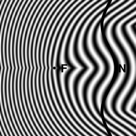
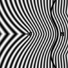
The images are shown as gray levels proportional to , with a scale constant, so that they depict as fringes the families obtained when the parameter is increased in a continuous way.
The shape of the fringes indicates the loci of stationary optical path sum or difference and the geometry of a diopter such that when illuminated by a point source at generates a wave front in the shape of . The orientation and spacing of these fringes indicates the sensitivity to phase variations. Places where fringes are dense indicate that phase changes fast there with position, while the direction of the fringes indicates the zero sensitivity direction. Loci of equal sensitivity, that is the curves defined by Abramson, can be numerically determined from these figures. Phase changes or departure of the calculated values could be due, for example, to construction errors in the refracting surfaces. Then, the spacing between the fringes is an estimation of its local construction tolerance.
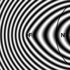
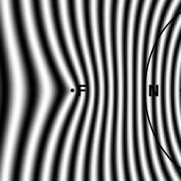
Figures 4 and 5 show the generalized Abramson (GAHD) and Young (GYHD) holodiagrams for a convex elliptical wave front. Figures 6 and 7 show the generalized Abramson (GAHD) and Young (GYHD) holodiagrams for a wave front with sinusoidal form.
In a similar way as in other holodiagrams, a cut of these diagrams by an arbitrary surface defines a generalized Fresnel Zone Plate. The now known as Fresnel Zone Plate was invented by Lord Rayleigh; he wrote in 1871: ”The experiment of blocking out the odd Huygens Zones so as to increase the light of the center succeeded very well…” jenkins . A classical Fresnel Zone Plate is a diffraction gratings device that consists in a binary pupil that is transparent in alternate Fresnel zones and absorbing in the rest. When it is illuminated by a spherical wave front, constructive interference occurs in certain points of its axis and high intensity is observed there, so that these points can be considered as images of the source. For each image point it can be considered as a device that maps a spherical diverging wave front from the source into a spherical converging wave front to the image or as the hologram of a point, being all these descriptions equivalent. We are going to call a Generalized Fresnel Zone Plate (GFZP) to a pupil that diffracts a predetermined wave front when illuminated by a given one, in our case a spherical diverging wave or, conversely it maps a given wave front into a spherical converging wave. The GFZP is indeed a hologram and the new name is assigned to it only to help in its interpretation.
Now, let us assume, as Abramson does, that the GRHD has the imaginary property to paint the surfaces it intersects with its local gray level. For easy description let us also assume that we use a binary version of the GRHD, that is, we use the approximation that the sine wave of light is just a square wave that has one half in antiphase with the other. Then, when the GRHD cuts any arbitrary shaped surface , limiting the media with the refractive indices used in its calculation, a series of painted and transparent regions are defined on the surface. If the so painted surface is now illuminated by a point source at F it will be transmitted only in the transparent regions. That is to say that only points fulfilling the condition that the sum of the optical paths between and tha wave front differ in integer multiples of , will contribute to the transmitted wave front. The painted surface behaves as a hologram that when illuminated by a wave front coming from diffracts a wave front congruent with and conversely. We can say then that such a cut is a Generalized Fresnel Zone Plate.
It can be easily seen that, if the refracting surface is itself a refracting profile, then the Fresnel Zone plate is not needed: the surface is uniformly transparent. Then, if a certain refracting surface shape is close to that of a refracting profile, this Fresnel Zone plate or hologram will show extensive uniform regions. This means that the Fresnel Zone plate so generated can be used to correct construction phase errors in a refracting profile and it will consist in a low spatial frequency register.
Finally we will give another optical application of the refracting profiles construction: As, when the incident wave front is , after refraction in the profile the wave front is spherical converging to or diverging from , the second medium can be finished as a spherical surface centered in rabal6 followed by the same refracting medium with index or any other. Then, the focusing profile becomes a lens that either selectively focuses a given wave front or synthesizes from a predetermined wave front in the same medium. As shown in reference rabal7 , the second surface finishing needs not to be exclusively spherical but can also be in the shape of a Cartesian oval. Moreover, as the refracted wave front is spherical converging to , the same concept described here permits to design the second surface as a second refracting profile. The composite effect of the two cascaded refracting profiles acts then as a particular lens that maps a predetermined wave front into another also predetermined wave front after two refractions.
Conversely, a spherical wave front, either diverging from or converging to a point , can be mapped with a refracting profile into another wave front and the latter again mapped after a second refraction to a diverging or converging wave front with the same or other focus . The composite effect is that of a sort of lens that conjugates a point source to the final focus with an encryption step between. The generalization of the HD to two more arbitrary wave fronts will be treated in a forthcoming work.
5 Conclusions
We have proposed a generalization of the classical concept of Holodiagram with respect to one wave front. It is based on the concepts of refracting and focusing profiles recently developed. Regions corresponding to caustics and auto intersections need to be excluded. We have shown some characteristic examples.
The use of the new compound concept can be found not only in getting insight about wave front propagation but also in the design of computer generated holograms to synthesize predetermined wave fronts, in pattern recognition of specified wave fronts, in the mapping of a wave front into another, in the calculation of tolerances in special lenses construction, in elementary ray tracing, encryption, etc.
Acknowledgements
This work was partially supported by Spanish grants FQM-192 (C. Criado) and BFM2001-1825 (N. Alamo), and CONICET and Faculty of Engineering, Universidad Nacional de La Plata, Argentina (H. Rabal).
References
- (1) N. Abramson, The Holo-diagram, a practical device for making and evaluation of holograms, Appl. Opt. 8 (1969) 1235–1240.
- (2) N. Abramson, Light in Flight or The Holodiagram, Columbi egg in optics, (SPIE, Bellingham, 1996).
- (3) N. Abramson, The making and evaluation of holograms, (Academic Press, London, 1981).
- (4) N. Abramson, The holodiagram as a teaching tool, Opt. Eng.32 (1993) 508–513.
- (5) N. Abramson, The Holo-Diagram II: a practical device for information retrieval in hologram interferometry, Appl. Opt. 9,97-1101 (1970)
- (6) N. Abramson, The Holo-diagram III: A practical device for predicting fringe patterns in hologram interferometry, App. Opt.9, 2311–2320 (1970)
- (7) H. Rabal, The holodiagram with virtual sources, Optik 112 (2001) 487–492.
- (8) G. Baldwin, F. De Zela and H. Rabal, Refraction holodiagrams, Optik 112 No. 12 (2001) 555–560.
- (9) N. Cap, B. Ruiz, H. Rabal, Refraction holodiagrams and Snell’s law, Optik 114 No. 2 (2003) 89–94.
- (10) H. Rabal, N. Cap, K. Gottschalk, M. Simon, Holodiagrams in birefringent media, Applied Optics-IP 42 Issue 29 (2003) 5825–5830.
- (11) H. Rabal, The holodiagram in a geometrical approach to the calculation of fringes visiblity, Optik 113 No. 6 (2002) 260–266.
- (12) C. Criado, N. Alamo, Optical properties of conics: a method for obtaining reflecting and focusing profiles, Opt. Comm. 167 (1999) 83–88.
- (13) N. Alamo, C. Criado, Generalized antiorthotomics and their singularities, Inverse Problems 18 (2002) 881–889.
- (14) H. Rabal , N. Alamo, C. Criado, Reflecting profiles and generalized holodiagrams, Optik 114 No. 8 (2003) 370–374.
- (15) N. Alamo, C. Criado, A method to construct refracting profiles, Inverse Problems 20 (1) (2004) 229–238.
- (16) E. H. Lockwood, A book of curves, (Cambridge University Press, Cambridge, 1961)
- (17) F. A. Jenkins and H. E. White, Fundamentals of Optics, (MacGraw-Hill, New York, 1976)