Slow-light enhancement of Beer–Lambert–Bouguer absorption
Abstract
We theoretically show how slow light in an optofluidic environment facilitates enhanced light-matter interactions, by orders of magnitude. The proposed concept provides strong opportunities for improving existing miniaturized chemical absorbance cells for Beer–Lambert–Bouguer absorption measurements widely employed in analytical chemistry.
pacs:
42.70.Qs, 42.25.Bs, 87.64.Ni, 82.80.DxOptical techniques are finding widespread use in chemical and bio-chemical analysis, and Beer–Lambert–Bouguer (BLB) absorption in particular has become one of the classical workhorses in analytical chemistry Skoog:1997 . During the past decade, there has been an increasing emphasize on miniaturization of chemical analysis systems Janasek:2006 and naturally this has stimulated a large effort in integrating microfluidics Squires:05 ; Whitesides:2006 and optics in lab-on-a-chip microsystems Verpoorte:2003 , partly defining the emerging field of optofluidics Psaltis:2006 ; Monat:2007a . At the same time, there is an increasing attention to slow-light phenomena as well as the fundamentals and applications of light-matter interactions in electromagnetically strongly dispersive environments Lodahl:2004 ; Soljacic:2004 ; Vlasov:2005 ; Jacobsen:2006 ; Noda:2006 . In this Letter we consider the classical problem of BLB absorption. As with the phenomenon of photonic band-edge lasing Dowling:1994 , we show how slow light in an optofluidic environment facilitates enhanced light-matter interactions, by orders of magnitude, with strong opportunities for improving existing miniaturized chemical absorbance cells.
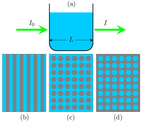
The principle of a BLB measurement is illustrated in panel (a) of Fig. 1 with an optical probe, with intensity , incident on a sample with absorption parameter due to a concentration of some chemical species. Typically the chemicals will be dissolved in a liquid, but gas and transparent solid phases are in principle also possible. Neglecting coupling issues, the transmitted intensity will then, quite intuitively, be exponentially damped, , with being the optical path length and being a dimensionless measure of the slow-light enhanced light-matter interactions. For a uniform medium of course, we have and the expression is often referred to as Beer’s law. Since correlates with the concentration of the absorbing chemical species, Beer’s law provides optical means for detecting and quantifying the concentration of chemical solutions Skoog:1997 . Obviously, the effect relies heavily on having a sufficiently long optical path length and the longer is the lower a concentration can be monitored for a given sensitivity of the optical equipment measuring . Lab-on-a-chip implementations of chemical absorbance cells are thus facing almost exhausting challenges since the miniaturization, i.e. reduction of , decreases the sensitivity significantly. This problem has already been confirmed experimentally for lab-on-a-chip systems operated in the visible with of the order to Mogensen:2003 . In this work, we show a route to achieve enhancement factors much larger than unity, thus potentially compensating for the cost of miniaturization and reduction in optical path length.
In order to explicitly show this phenomenon, we start from the electromagnetic wave equation for the electrical field,
| (1) |
and consider the case of a weakly absorbing medium with . Since absorption is a weak perturbation, , standard first-order electromagnetic perturbation theory is fully adequate to predict the small imaginary shift in frequency, . For the unperturbed problem, we may obtain the dispersion relation by solving the wave equation (see method section) with . For a fixed frequency, the perturbation changes into an imaginary shift of the wave vector so that the absorption parameter becomes , where the electrical field is the unperturbed field in the absence of absorption, is the group velocity, and is the free-space wave vector. As a reference we consider a homogeneous liquid with where we have a linear dispersion with a group velocity of and thus . Next, imagine that the dispersion is modified by introducing a non-absorbing (at least compared to the liquid) material of different index in the liquid, see panels (b–d) in Fig. 1. Compared to the bare liquid such a composite medium may support an enhancement of the effective absorption. The enhancement factor can now be expressed as
| (2) |
where we have introduced the displacement field . The integral in the nominator of the filling factor is restricted to the region containing the absorbing fluid while the integral in the denominator is spatially unrestricted. This expression clearly demonstrates how BLB absorption benefits from slow-light phenomena. For liquid infiltrated photonic crystals and photonic crystal waveguides, it is possible to achieve and at the same time have a filling factor of the order unity, , whereby significant enhancement factors become feasible. The effective enhancement of the absorption can also be understood in terms of an effective enhancement of the light-matter interaction time given by the Wigner–Smith delay time . For the homogeneous problem, we have while for the strongly dispersive problem so that in agreement with the result in Eq. (2) rigorously derived from perturbation theory. The presence of the filling factor is also easily understood since only the fraction of the light residing in the fluid can be subject to absorption. These conclusions may be extended to also non-periodic systems, including enhanced absorption in disordered systems as well as intra-cavity absorbance configurations, by use of scattering matrix arguments Beenakker:2001 .
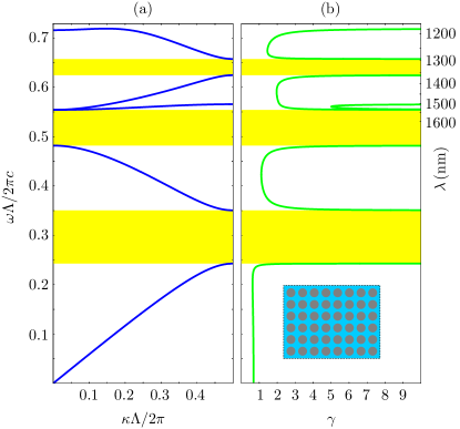
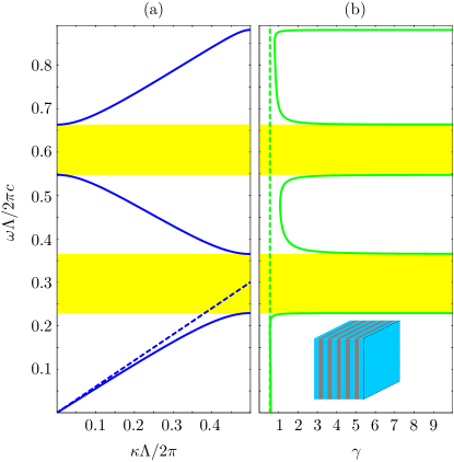
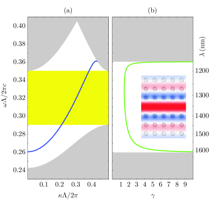
Let us next illustrate the slow-light enhancement for the simplest possible structure; a Bragg stack with normal incidence of electromagnetic radiation. Panel (a) of Fig. 2 shows the photonic band structure of an optofluidic Bragg stack of period with the low-index material layers of width being a liquid with refractive index while the high-index layers have a width and a refractive index . Photonic band gaps are indicated by yellow shading and the dashed line indicates the long-wavelength asymptotic limit where the Bragg stack has a meta-material response with a close-to-linear dispersion . When approaching the band-gap edges, the dispersion flattens corresponding to a slow group velocity. It is well-known that the flat dispersion originates from a spatial localization of the field onto the high-index layers and thus near the band edges where the inverse group velocity diverges. However, in spite of the localization, the enhancement factor may still exceed unity as shown in panel (b) where the dashed line indicates the long-wavelength asymptotic limit with . In order to further benefit from the slow-light enhanced light-matter interaction, we obviously have to pursue optofluidic structures supporting both low group velocity and at the same time large filling factors. Fig. 3 shows one such example where high-index dielectric rods are arranged in a square lattice. Compared to the Bragg stack, some of the modes in this structure have both a low group velocity and at the same time a reasonable value of the filling factor . Particularly the third band in panel (a) is quite flat and with a finite giving rise to an enhancement factor exceeding 5 even at the centre of the band. As indicated on the right -axis, the enhancement may have a bandwidth of order 50 nm for a pitch around , which indeed makes fabrication of such structures realistic with state of the art micro and nano fabrication facilities. As a final example, Fig. 4 shows the result of introducing a line-defect waveguide in such a structure. The waveguide mode has combined with a low group velocity near the band edges.
For the above numerical results, fully-vectorial eigenmodes of Maxwell’s equations, Eq, (1), with periodic boundary conditions were computed by preconditioned conjugate-gradient minimization of the block Rayleigh quotient in a planewave basis, using a freely available software package Johnson:2001 . For the resolution, we have used a basis of plane waves for the 1D problem in Fig. 2 and plane waves for the 2D problem in Fig. 3. In Fig. 4 we have used a resolution of and a super-cell of size .
In the above examples we have for simplicity considered dielectric constants corresponding to semiconductor materials suitable for the near-infrared regime. However, we would like to emphasize that applications exist also in the visible, mid-infrared, far-infrared, and even the microwave and sub-terahertz regimes. The predicted enhancement of light-matter interactions makes liquid-infiltrated photonic crystals obvious candidates for improving existing miniaturized chemical absorbance cells. Previous work on liquid-infiltrated photonic crystals Loncar:2003 ; Chow:2004 ; Kurt:2005 ; Erickson:2006 ; Hasek:2006 has focused on the solid type with liquid infiltrated voids illustrated in panel (d) of Fig. 1, while we in this work have focused on rod-type photonic crystals which have the technological strong advantage that they are permeable to an in-plane liquid flow, thus making them integrable with micro-fluidic channels in planer lab-on-a-chip technology.
In conclusion, we have studied the potential of using liquid-infiltrated photonic crystals to enhance Beer–Lambert–Bouguer absorption. The slow-light enhancement of the absorption, by possibly orders of magnitude, may be traded for yet smaller miniaturized systems or for increased sensitivity of existing devices.
Acknowledgments. This work is financially supported by the Danish Council for Strategic Research through the Strategic Program for Young Researchers (grant no: 2117-05-0037).
References
- (1) D. A. Skoog, D. M. West, and F. J. Holler, Fundamentals of Analytical Chemistry (Saunders College Publishing, New York, 1997).
- (2) D. Janasek, J. Franzke, and A. Manz, Nature 442, 374 (2006).
- (3) T. M. Squires and S. R. Quake, Rev. Mod. Phys. 77, 977 (2005).
- (4) G. M. Whitesides, Nature 442, 368 (2006).
- (5) E. Verpoorte, Lab Chip 3, 42N (2003).
- (6) D. Psaltis, S. R. Quake, and C. H. Yang, Nature 442, 381 (2006).
- (7) C. Monat, P. Domachuk, and B. J. Eggleton, Nature Photonics 1, 106 (2007).
- (8) P. Lodahl, A. F. van driel, I. S. Nikolaev, A. Irman, K. Overgaag, D. L. Vanmaekelbergh, and W. L. Vos, Nature 430, 654 (2004).
- (9) M. Soljacic and J. D. Joannopoulos, Nature Materials 3, 211 (2004).
- (10) Y. A. Vlasov, M. O’boyle, H. F. Hamann, and S. J. McNab, Nature 438, 65 (2005).
- (11) R. S. Jacobsen, K. N. Andersen, P. I. Borel, J. Fage-Pedersen, L. H. Frandsen, O. Hansen, M. Kristensen, A. V. Lavrinenko, G. Moulin, H. Ou, C. Peucheret, B. Zsigri, and A. Bjarklev, Nature 441, 199 (2006).
- (12) S. Noda, Science 314, 260 (2006).
- (13) J. P. Dowling, M. Scalora, M. J. Bloemer, and C. M. Bowden, J. Appl. Phys. 75, 1896 (1994).
- (14) K. B. Mogensen, J. El-Ali, A. Wolff, and J. P. Kutter, Appl. Optics 42, 4072 (2003).
- (15) C. W. J. Beenakker and P. W. Brouwer, Physica E 9, 463 (2001).
- (16) S. G. Johnson and J. D. Joannopoulos, Opt. Express 8, 173 (2001).
- (17) M. Lončar, A. Scherer, and Y. M. Qiu, Appl. Phys. Lett. 82, 4648 (2003).
- (18) E. Chow, A. Grot, L. W. Mirkarimi, M. Sigalas, and G. Girolami, Opt. Lett. 29, 1093 (2004).
- (19) H. Kurt and D. S. Citrin, Appl. Phys. Lett. 87, 241119 (2005).
- (20) D. Erickson, T. Rockwood, T. Emery, A. Scherer, and D. Psaltis, Opt. Lett. 31, 59 (2006).
- (21) T. Hasek, H. Kurt, D. S. Citrin, and M. Koch, Appl. Phys. Lett. 89, 173508 (2006).