Goos-Hänchen induced vector eigenmodes in a dome cavity
David H. Foster
Deep Photonics Corp., 5121 SW Hout St., Corvallis, OR, 97333
Andrew K. Cook and Jens U. Nöckel
Department of Physics, University of Oregon, 1371 E 13th Avenue, Eugene, OR, 97403
Abstract
We demonstrate numerically calculated electromagnetic eigenmodes of a 3D dome cavity resonator that owe their shape and character entirely to the Goos-Hänchen effect. The V-shaped modes, which have purely TE or TM polarization, are well described by a 2D billiard map with the Goos-Hänchen shift included. A phase space plot of this augmented billiard map reveals a saddle-node bifurcation; the stable periodic orbit that is created in the bifurcation corresponds to the numerically calculated eigenmode, dictating the angle of its “V”. A transition from a fundamental Gaussian to a TM V mode has been observed as the cavity is lengthened to become nearly hemispherical.
OCIS codes: 140.4780, 260.5430, 260.2110, 230.5750
The Goos-Hänchen (GH) effect[1], which typically occurs upon reflection from a dielectric interface or layered structure, is an apparent parallel translation of the reflected beam away from its geometrically expected position. A simple treatment[2] shows that the size of the GH shift is proportional to the derivative of the reflection phase with respect to the angle of incidence. In addition to shifting beam position, the the GH effect can manifest itself in alterations of differential cross sections[3], of laser mode dynamics[4], and of mode spectra [5].
Here we present and analyze a class of eigenmodes in a non-paraxial dome cavity, the “V modes”, showing that the modes are straightforwardly explained by a stable periodic orbit in a billiard map that is augmented by the Goos-Hänchen effect. A ray analysis of the cavity geometry without taking the Goos-Hänchen shift into account fails to predict these modes. To the authors’ knowledge, this Letter presents the first demonstation of the GH effect, or any nonspecular effect[6], creating entirely new eigenmode patterns.
Our model dome cavity consists of a perfectly conducting concave spherical mirror, M1, facing a planar thin film (distributed Bragg reflector), denoted by M2. The electromagnetic eigenmodes are calculated by the basis expansion methods which are fully described in Ref. 7. We first described the V modes in Ref. 7, but no physical explanation for their appearance has been put forward until now.
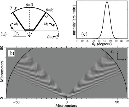
To provide quantitative results, we fix some parameters at the outset, cf. Fig. 1(a): The radius of M1 is m and the length of the resonator, measured from the front surface of M2 to the zenith of M1, is , where we will focus on the range m. This means the resonator is nearly hemispherical, and increasing mirror offset makes the cavity more paraxial. The layer structure of M2 is where denotes the vacuum region inside the cavity, each denotes a layer of material (AlGaAs) of quarter wave thickness at nm, each denotes a layer of material (AlAs), also of quarter wave thickness at nm, and denotes the vacuum region outside the cavity.
Axial symmetry allows one to label all cavity modes by a total angular momentum quantum number ; the complex electric and magnetic fields , , , , , and (in cylinder coordinates) are proportional to . In this paper, we present data only for modes with . The vectorial eigenmodes typically found in an axially symmetric cavity are in general neither TE nor TM. Here, TE refers to fields whose angular spectrum contains only s-polarized plane waves with respect to the Bragg mirror; TM denotes a p-polarized plane wave decomposition.
Fig. 1(b) shows a V mode having wavelength nm at m. The contrast-enhanced plot shows the - slice of the physical field ( is the dome axis). Azimuthally, the electric field here is proportional to , which may be combined to make the “linearly” polarized versions . The V mode is almost completely TE polarized. Fig. 1(c) shows the s-polarized (TE) polar angle distribution of plane waves, , for this mode; is the angle of incidence of a plane wave with respect to the cavity axis. The p-polarized admixtures are negligible on the scale of the plot.
Averaging against this distribution yields , which one can identify as the “opening angle” of the V-shaped beam. Similar modes have been observed which are entirely TM. We also found TE modes which exhibit a transverse node in each side of the V. This leads us to introduce the notation VTM and VTE for these V modes, where is the total angular momentum and is the number of nodes in the transverse wavefunction of each side of the V. The mode in Fig. 1 is then VTE.
We now turn to the explanation of these V modes in terms of the Goos-Hänchen effect: The GH shift along the reflecting surface, of an s- or p-polarized beam is[2]
| (1) |
where and is the plane wave reflection phase of the surface. A simple self-retracing periodic orbit which reflects perpendicularly from M2 can exist at if the GH shift equals the geometrically determined segment, that is if
| (2) |
where the right hand side is seen to be the length of the horizontal segment of the orbit shown (bold line) in Fig. 1(a).
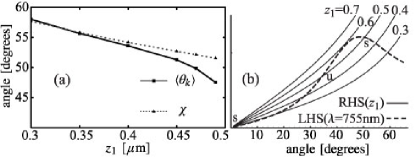
Since is given physically and may be coarsely chosen, Eq. (2) is in practice solved for or to predict the angle of the V modes. The prediction for the VTE mode shown in Fig. 1 is , in excellent agreement with the average angle obtained for the numerically calculated eigenmode. Numerical experimentation shows that increases to near as . Fig. 2(a) shows good agreement between and for a VTE mode followed from to . (Following the VTE mode pattern over this range required “hopping” across mode anticrossings at and .)
To characterize the conditions under which the V modes are stable, it is useful to investigate the phase-space of the classical ray dynamics. The ray orbit shown in Fig. 1(a) is a periodic orbit (PO) of a billiard map which obeys specular reflection at the top mirror M2, but at M1 receives a GH shift, along the M1 surface, the length of which is given by Eq. (1). To specify this map, we follow a ray through multiple reflections, and just before the -th bounce at mirror M2, note its polar coordinate as shown in Fig. 1(a), as well as the component of the (unit) momentum in the direction. The billiard map maps this pair of ray properties from one reflection at M2 to the next one:
| (3) |
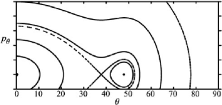
A plot of nine trajectories, each of 1000 bounces, of the map for and s-polarization (TE) is shown in Fig. 3. Such a phase space plot is very much like the Poincaré section of a dynamical system and may be analyzed as such. The island structure surrounding the stable PO manifests itself in wave physics as the family of paraxial Gaussian modes. The separatrix indicates an unstable PO at and the second island indicates a stable PO at . As shown in Fig. 2(b), these two POs are created at the same point (this is called a saddle-node bifurcation) as is lowered to about , and move apart in as is further decreased. As decreases, the island shrinks, while the new island grows. As it grows, one or more existing wave modes may become distorted until one of them becomes the V mode; the V modes live inside the new island. If the GH effect is turned off in the billiard map (3), there is no new island, and the only PO that exists is the orbit. This leads to the important conclusion that only a ray map augmented by the GH effect predicts the stable cavity modes correctly. This analysis can be applied equally to the s- or p-polarized V modes, by inserting the appropriate reflection phase in the map .
At sufficiently large mirror offset , we should be able to make contact with Gaussian-beam theory. The resonator modes may be characterized by their transverse field patterns, which are described in Refs. 8, 9, 7, 10, 11. In Refs. 7, 10, 11, a dielectric mirror provides a form birefringence which causes the transverse mode patterns of many typical eigenmodes to be symmetric and antisymmetric mixtures of specific pairs of vectorial Laguerre-Gauss modes, causing either TE or TM polarization to dominate the plane-wave spectrum. Starting from paraxial theory, these “mixed” modes can be denoted by the transverse order , the angular momentum , and whether or not they are quasi-TE or quasi-TM:
| (4) |
for , , and . Here is the Jones vector for right/left circular polarization and LG denotes the Laguerre-Gauss wave pattern[10]. A detailed discussion of the mixed modes is given in Ref. 11; they, along with pure Gaussians occuring for , comprise the background of eigenmodes against which the V modes appear.
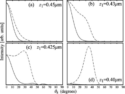
We numerically observe that V modes evolve from some existing mode of this paraxial type as is reduced and the stable island grows. As an example of this metamorphosis, a VTE mode was created from the predominantly TE mixed mode having the tranverse E field, in the paraxial limit, given by . On the other hand, as shown in Fig. 4, a VTM mode was created from the fundamental Gaussian mode TEM00, which originally has circular polarization. The polarization-dependent stabilization provided by the GH effect thus overcomes the polarization state expected for the paraxial fundamental mode in an axially symmetry cavity. This non-paraxial nature of the V modes underlines the predictive power of the Goos-Hänchen picture.
Although the numerical results presented here were limited to , we have observed VTM, VTE, and VTE, and expect V modes to generally exist for . Other dielectric stack designs than the one described here have also been observed to induce V modes.
We note that patterns reminiscent of the V modes appear in an earlier work by Blümel et al.[12] which discusses scalar waves in a purely two-dimensional circle with a dielectric boundary across its diameter. This roughly corresponds to the limit in our model, and neither the question of the GH effect nor the dependent opening angle of the V modes are addressed in that work. As pointed out in Ref. 12, semiclassical techniques that may be appropriate for smoothly varying media or simple boundary conditions (e.g., Dirichlet) need to be extended in the presence of dielectric interfaces. The results presented here were obtained in a simpler and physically appealing way, by adding nonspecular corrections to the classical ray mapping .
The V modes demonstrate that small corrections to specular reflection, such as the Goos-Hänchen shift, can have large qualitative effects. Billiard models augmented by nonspecular corrections possess new phase space structures which correspond to the new modes. The V mode in particular provides a potential lasing mode with two or four entrance/exit channels, yet it economically uses only one curved surface. Interestingly, the spreading angle of each limb of the V modes is smaller than predicted by a Gaussian-beam calculation based on the path length of the V including GH shift. In future work, we will investigate to what extent a stability analysis of the ray map is able to explain this phenomenon.
This work was supported by NSF Grant ECS-0239332.
References
- [1] F. Goos and H. Hänchen, “Ein neuer and fundamentaler Versuch zur total Reflection,” Ann. Phys. Leipzig 1, 333–345 (1947).
- [2] K. V. Artmann, “Berechung der Seitenversetzung des totalreflektierten Strahles,” Ann. Phys. Leipzig 2, 87–102 (1948).
- [3] N. H. Tran, L. Dutriaux, P. Balcou, A. Le Floch, and F. Bretenaker, “Angular Goos-Hänchen effects in curved dielectric microstructures,” Opt. Lett. 20, 1233–1235 (1995).
- [4] L. Dutriaux, A. Le Floch, and F. Bretenaker, “Goos-Hänchen effect in the dynamics of laser eigenstates,” J. Opt. Soc. Am. B 12, 2283–2289 (1992).
- [5] D. Q. Chowdhurry, D. H. Leach, and R. K. Chang, “Effect of the Goos-Hänchen shift on the geometrical-optics model for spherical-cavity mode spacing,” J. Opt. Soc. Am. A 11, 1110–1116 (1994).
- [6] W. Nasalski, “Longitudinal and transverse effects of nonspecular reflection,” J. Opt. Soc. Am. A 13, 172–181 (1996).
- [7] D. H. Foster and J. U. Nöckel, “Methods for 3-D vector microcavity problems involving a planar dielectric mirror,” Opt. Commun. 234, 351–383 (2004).
- [8] P. K. Yu and K. Luk, “Field patterns and resonant frequencies of high-order modes in an open resonator,” IEEE Trans. Microwave Theory Tech. 32, 641–645 (1984).
- [9] K. Y. Bliokh and D. Y. Frolov, “Spin-orbit interaction of photons and fine splitting of levels in ring dielectric resonator,” Opt. Commun. 250, 321–327 (2005).
- [10] D. H. Foster and J. U. Nöckel, “Bragg-induced orbital angular-momentum mixing in paraxial high-finesse cavities,” Opt. Lett. 29, 2788–2790 (2004).
- [11] D. H. Foster, “Fabry-Perot and whispering gallery modes in realistic resonator models,” Ph.D. thesis, University of Oregon (2006)
- [12] R. Blümel, T. M. Antonsen, B. Georgeot, E. Ott, and R. E. Prange, “Ray Splitting and Quantum Chaos,” Phys. Rev. Lett. 76, 2476–2479 (1996).