Waveplate retarders based on overhead transparencies
Abstract
We describe procedures for constructing inexpensive waveplates of desired retardation out of ordinary commercially available transparencies. Various relevant properties of the transparencies are investigated: the dependence of retardation on rotation of the film, tilt, wavelength, position, and temperature. Constructing waveplates out of combinations of transparency sheets is also explored.
pacs:
42.25.Ja,42.70.-a,42.79.-e, 81.05.-t,81.05.LgI Introduction
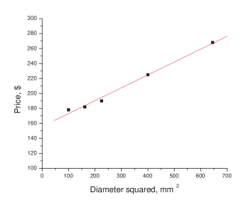
Conventionally, retarders are made of calcite, quartz, or mica Hecht and Zajac (1979); Walter and William (1978); boo (1997-98). In applications of wave plates in which low price and rapid availability are more important than high quality, the construction of wave plates from inexpensive materials can be of great practical interest. For example, ordinary cellophane used in commercial packaging can be very close to a half-wave thickness for visible light, as mentioned by Richard Feynman in his famous lectures Feynman (1977), and wave plates can be constructed from this material. Recently, construction of a quarter-wave retarder for light at nm from the 3M PP2500TM polyester film was proposed Ortiz-Gutiérrez et al. (2000, 2004) and some properties of this film were investigated. While this film is inexpensive, it is not commonly found in a laboratory. In this paper we explore the possibility of using most common inexpensive overhead transparencies of different types (black and white, color, from different companies) as wave plates and test their quality in retarder applications. Apart from general interest in a broad class of applications, this project is also motivated by the need for cheap wave plates for building commercial and experimental optical atomic magnetometers based on optical pumping with circularly polarized light and detection of spins using light polarization measurements Allred et al. (2002). In magnetometer applications, large-size waveplates are often needed, while the price grows linearly with the wave-plate area as illustrated in Fig.1.
Overhead transparencies are made of polymer film produced by a process in which the film is extruded through a slit onto a chilled polished turning roll where it is quenched from one side. Additional film stretching can be employed for achieving desirable properties. Such stretching may produce biaxial materials, such as biaxially-oriented polyethylene terephthalate (boPET) film from which some overhead transparencies are made for copiers or laser printers. Refractive indices of boPET were studied in Ref. Elman et al. (1998). The extrusion and stretching processes in general lead to biaxial birefringence; however, it is possible that one preferential direction of molecular orientation is defined and one refractive index is more pronounced than the others and the medium can be approximated as uniaxial. For example, in Ref.Ratta et al. (2001), the structural properties of HDPE (High Density Polyethylene) film have been studied and it was found that draw ratio affected crystalline orientation and refractive indices approximately in the same way in two directions but quite differently in the third direction. Birefringence is a very general property of transparent polymers, including overhead transparencies. The theory of birefringence induced by mechanical deformation for polymers and liquid crystals is given in Ref.Stein et al. (1995). Optical properties are of great practical interest because they can be used to analyze the material structure and to control the extrusion process.
II Polarization properties of overhead transparencies
We investigate polarization properties of overhead transparencies with a commercial polarimeter, Thorlabs PAX5710IR1-T, which outputs the state of polarization in the form of a polarization ellipse with numerical values of the ellipticity and the azimuth as well as the Poincaré sphere with coordinates that are the three Stokes parameters , , and . The Stokes parameters can be found from the ellipticity and azimuth, or from the set of Jones vector parameters such as field amplitudes and and phase shift , or vice versa Born and Wolf (1993). For example, the ellipticity and azimuth are related to the Jones vector parameters through the following equations
| (1) |
| (2) |
It is convenient to parameterize normalized field amplitudes as and , so ellipticity and azimuth depend only on two variables,
| (3) |
| (4) |
Equation 3 will be used throughout the paper to relate the polarimeter’s output to a more fundamental property of optical material such as retardation and to fit experimental data in which or are varied.
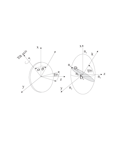
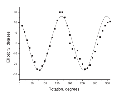
First, to verify that transparency can operate as a wave plate, we study the dependence of ellipticity on the transparency rotation angle. The experimental arrangement for this measurement is simple: a helium-neon laser beam (632.8 nm wavelength), linearly polarized with a Polaroid film, is sent to the detection head of the polarimeter through a fragment of transparency attached to a rotation mount with angular resolution of 1 degree. The rotation is defined in Fig.2, left panel. From this definition if transparency behaves as a waveplate the ellipticity of the transmitted light as a function of the transparency rotation must satisfy Eq. (3) in which is the transparency rotation angle. The ellipticity of the light as a function of this angle is shown in Fig.3. The behavior is periodic as expected for a wave plate, in accordance with Eq. (3), but some deviation from periodicity is observed which can be explained by the shift of the point where the laser beam intersects the transparency when it is not exactly in the center of rotation combined with spatial variations in the retardation that will be discussed later. The retardation is about 0.91 rad and because in the Taylor expansion of arcsine the first term is much larger than the others, we obtain that the dependence on the transparency rotation angle is dominantly a sine wave as is seen in Fig.3. The maximum value of ellipticity in this particular measurement is less than maximum possible 45 degrees of a plate. For constructing a plate a more appropriate part of the transparency has to be chosen or the plane of the transparency has to be tilted.
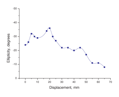
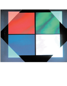
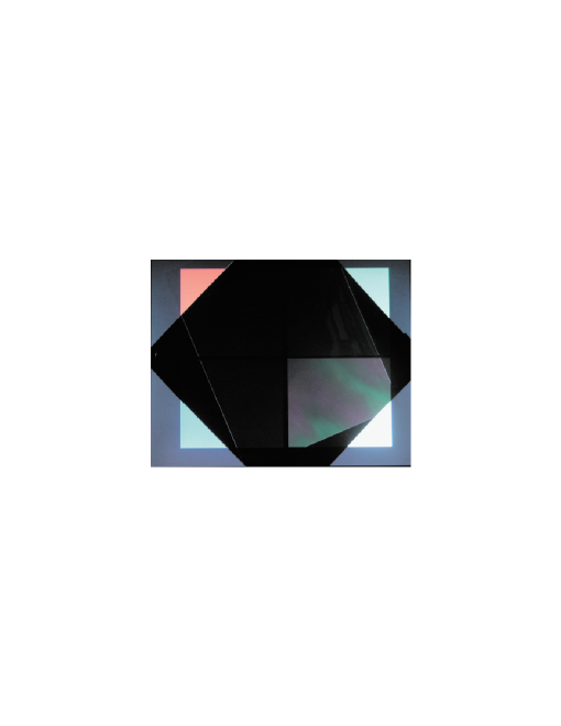
The next graph, Fig.4 demonstrates how the position of the transparency for a fixed orientation affects the induced ellipticity and hence retardation. Apart from demonstrating how the retardation can be optimized by spatial selection, this graph also gives information about typical retardation spatial non-uniformity in one dimension which is important for the determination of the useful size of the transparency wave plate. From the data, we see that the size is of order 1 cm. By using a computer screen and a crossed polaroid film it is possible to find regions with larger area of uniformity as demonstrated in Fig.5.
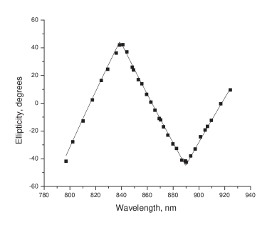
To understand the order of the transparency waveplate and to estimate the useful wavelength range where the transparency can function as a waveplate of a given type, we measured the wavelength dependence of the ellipticity of a transparency using a tunable Ti:Sapphire laser as light source (Fig.7). For a particular angle , chosen in the experiment to give maximum ellipticity, Eq. (3) predicts the dependence of ellipticity on retardation as a triangle wave with an amplitude 45∘. Because the retardation changes approximately linearly with wavelength in some range
| (5) |
the ellipticity follows a quasi-periodic triangle wave as a function of wavelength as observed experimentally. The distance between zeros can be used to obtain total retardation.
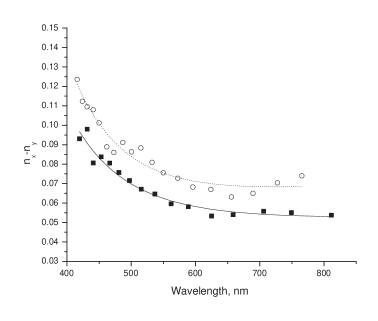
It is necessary in general to have the dependence of refractive index on wavelength to obtain total retardation. Such dependence is often approximated with the Cauchy dispersion formula which is accurate when wavelength of the light is far from resonances. For wavelengths shown in the Fig.7 the constancy of refractive index is a good approximation. In a larger range, from 300 nm to 900 nm, this assumption is not satisfied since a strong absorption band is located near 300 nm. We used a Varian CARY219 spectrometer to investigate the refractive index variation in the range 400-800 nm. A transparency film was inserted between two crossed polaroid films with its x axis at 45∘, so the transmission depended on the retardation. The wavelength of minima (or maxima) of the transmitted intensity could be used to calculate the refractive index difference as a function of wavelength. The results are plotted in Fig.8. Below 600 nm the wavelength dependence of refractive indices becomes significant, and a good fit requires retaining and terms as it is shown in Fig.8.
It is interesting to note that a transparency between two polarizers can serve as a birefringent filter. Investigation of such filters based on low-cost polymers has been carried out in Ref.Velasquez et al. (2004) where filters with bandwidth 50 nm were demonstrated.
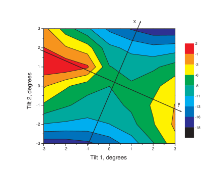
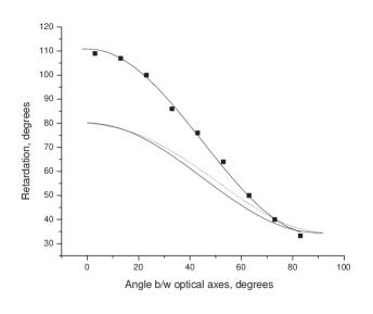
It might be convenient to adjust the retardation to a desirable level by tilting a transparency waveplate. The dependence on the tilt is determined by two factors: one is the increase in the optical path, and the other is the change in the retardation per unit length. In the general case of a biaxial medium the dependence of retardation and ellipticity on the tilt angle is quite complicated and for the analysis it is important to find the principal axes of the index ellipsoid, see Fig.2. To first approximation one in-plane principal axis, x or y, with the assumption to be justified in a moment that z is normal to the transparency, can be found easily by determining tilt direction for which the change in retardation for a small tilt angle () is the largest. From the dependence of retardation on the tilt angle (Eq.6) for this tilt direction we estimated that was about 0.2, much larger than obtained from the wavelength measurements at normal incidence (Fig.8) for the transparency of this type. Such small retardation for normal incidence means that the z axis of the index ellipsoid has a relatively small projection in the transparency plane and hence our zero-approximation assignment of refractive index subscripts is justified. After finding the z axis approximately, we can determine the principal refractive indices more accurately by investigating the retardation for small deviations of the transparency film normal from the z direction. If and are defined as the semi-axes of the ellipse obtained by the intersection of the plane normal to the vector with the index ellipsoid (Refs.Born and Wolf (1993); Saleh and Teich (1991)), the retardation is proportional to . For tilt of the ellipsoid around the x axis (Ref.Born and Wolf (1993), section 14.3.3),
| (6) |
( is the tilt angle, is the average refractive index), and the retardation decreases with tilt if while for the tilt around the y axis,
| (7) |
the retardation increases with tilt. For small tilt, in the first case the dependence is a downward parabola symmetric with respect to zero tilt; in the second case the dependence is an upward parabola. Generally, the dependence of retardation on the tilt has a saddle point with orthogonal symmetry axes. If two dimensional data are given, the direction of the principal axis z can be found as normal to the surface going through the saddle point, and that of x and y axes can be found as the lines of symmetry. In Fig.9, for example, the x axis constitutes about angle with horizontal axis. If this angle is known, then from the fitting for tilt is sufficient to obtain or . If we neglect small effect due to path elongation, then , close to our initial estimate.
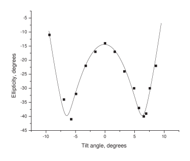
Different transparencies have slightly different properties, although qualitatively they are similar, including the orientation of the index ellipsoid. In Fig.9 we show tilt measurements for a 3M black and white transparency. To give an idea of variations, in Fig.10 we also present tilt measurements for the color transparency, with direction of the tilt around the x axis. This graph also illustrates the behavior of ellipticity in a larger tilt range and shows that 45∘ ellipticity can be achieved by tilting at a relatively small angle of 7∘. The dependence in Fig.10 is quite symmetric in accordance to the previously drawn conclusion that the z axis is orthogonal to the plane as depicted in Fig.2 on the left panel. We found using crossed polarizers that the x axis makes a constant angle about with respect to the edges of the transparency sheet across a large transparency area, although it varies for different samples. Using parabolic fits, we obtain , again much larger than in accordance with the z axis perpendicular alignment to the transparency plane. We have qualitatively investigated the dependence of ellipticity of this transparency on the tilt angle for different tilt direction, around x, y, and the xy bisector. The results are consistent with theoretical predictions: for the tilt around x - the dependence is a downward parabola, around y - upward, and for the tilt around xy the dependence is very slow (see Fig.9).
To complete the analysis it was also necessary to know the average refractive indices. We have measured them using Snell’s law by sending a 633-nm light beam at the edges of a stack of transparencies and by tracing incident and refracted rays. Several measurements for different incidence angles resulted in the average value . For comparison similar values at the same wavelength are obtained in Ref.Elman et al. (1998) for biaxially-stretched poly-ethyleneterephthalate (PET) films, , and in Ref.Martínez-Antón and Bernabeu (1998) for polyester biaxial stretched films, , while measurements in Ref.Ortiz-Gutiérrez et al. (2004) for 3M PP2500 films gave different result, . Such a high refractive index is uncommon for transparent organic materials which consist mostly of carbon and hydrogen, with single molecular bonds, and have similar densities. In order to check this result we conducted our own measurements using beam trace method as above for 3M PP2500 film. We found that for the polarization perpendicular to the plane of the sheet, (the spread is due to both inaccuracy and birefringence) and for the polarization in the plane of the sheet with error of measurements about 0.05, in disagreement with Ref.Ortiz-Gutiérrez et al. (2004).
It is also interesting to compare the results for the differences . Our results for two different transparency types are and . In Ref.Elman et al. (1998) for similar definition of principal axes, and , roughly in agreement. By interpreting results of Ref.Ortiz-Gutiérrez et al. (2004), the differences are of similar order. In general, birefringence depends strongly on the details of manufacturing process, so only qualitative agreement is expected.
III Applications
The simplest method to construct a desired wave plate for a given wavelength is to use a light source of this wavelength and to choose an appropriate area in a transparency sheet, monitoring retardation with either a commercial polarimeter or some other optical polarimetric arrangement. On the other hand, tuning can be achieved by tilting. Wavelengths for which transparency retarders can be constructed are in the wide range from visible to infrared. In particular, we tested operation at 633 nm with a helium-neon laser, at 790-930 nm with a Ti:Sapphire laser, and in the range of 300-900 nm with a spectrometer, as well as using a computer monitor with pure color settings.
In addition, we have also investigated the possibility of superposition of two transparency sheets for achieving desirable retardation. Since the eigenvectors of the Jones matrix of a combination of two waveplates are in general complex, the system has elliptical-polarization eigenstates and is not equivalent to a single waveplate which has eigenstates of linear polarization, except in some degenerate cases. In other words, the two-transparency combination can be viewed as a waveplate combined with a gyrotropic plate, whose effect is just a rotation of the polarization ellipse. If the purpose of the waveplate is, for example, to produce a polarization state with a given ellipticity starting with linearly polarized light, then a combination waveplate can generally be used for this. From the Jones-matrix formalism one finds that a two-transparency combination produces the same output ellipticity as a single waveplate, which has retardation between and depending on the angle between the fast axes of the two wave plates . For practical purposes this dependence can be interpolated with sufficient accuracy with
| (8) |
A comparison of numerical simulations with this interpolation equation for a typical case is shown in Fig.11. To confirm this theory, we investigated experimentally the behavior of two-sheet waveplates by rotating them and by varying the angle between the axes of the two constituent transparencies. First we tested that the ellipticity of two transparencies under the common rotation follows Eq. (3). Second, from the fits by Eq. (3) we found retardation for different relative orientations of the transparencies. Figure 11 summarizes the analysis and shows that the interpolation equation (Eq. (8)) agrees with the experimental data. In principle, even a single transparency sheet may have gyrotropy. Experimentally, we found that a single sheet of transparency does not change polarization if input polarization is aligned with the optical axis; so a single transparency behaves as a true birefringent wave plate.
It is interesting to note that when the angle between the fast axes of two transparency sheets is 90∘, the combined retardation will be lower, meaning that the order is lower, and the sensitivity to variations in parameters, such as temperature and wavelength, will be also lowered due to cancelation. This is a common technique for building low-order wave plates and is described for example in Ref.boo (1997-98).
Although the fast wavelength dependence of the retardation for a single sheet would limit the range of operation of a transparency wave plate to 10 nm (Fig.7), a combined plate can work in a much larger range.
One additional possibility is to combine a high-quality wave plate, which has some retardation offset due to operation at a non-nominal wavelength, with a two-transparency wave plate to compensate the offset. If we choose a 90-degree relative orientation in the combined transparency wave plate, the temperature stability of the resulting wave plate will not be significantly reduced.
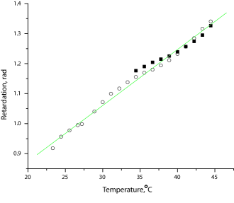
Similarly, although the temperature dependence of the retardation of a transparency is substantial, as shown in Fig.12, the combined wave plate has a much weaker temperature dependence. The same is also true for the more conventional composite low-order optical, for example, crystalline quartz, plates boo (1997-98). This dependence is linear in a wide range, which can be explained by linear thermal expansion. Assuming that the expansion is isotropic and , where is the coefficient of linear expansion and is the relative change in the length for temperature increment , the density is reduced by and the total retardation is reduced by , where we have taken into account the change in the plate’s length. From the total retardation of the transparency of the order rad (for , [Fig.8]), we can estimate the coefficient of linear expansion to be , in agreement with the common values for such materials, Ref.Kaye and Laby (1995). Apart from being a parasitic effect, the temperature dependence can be used in some applications. For example, it is possible to construct multi-channel thermometers based on monitoring retardation using broad light beams. Another application is the conversion of UV or IR images into visible ones by measuring retardation across the transparency (the local retardation is affected by heating with the absorbed UV or IR light). For small sizes, the transparency retardation is uniform and imaging can be implemented directly, but for large sizes non-uniformity can be taken into account with a computer. It is interesting to note that using sensitive polarimeters with fundamental photon shot noise on the order of 10-9 rad/Hz1/2, it should be possible to measure temperature changes as small as Kelvin with a single sheet and even better using a stack of transparencies. Other parameters such as ambient pressure or electric field (Kerr effect), can be measured with high sensitivity. Electric field imaging can be also of interest.
The wavelength dependence of the retardation (Fig.7) can be also used for sensitive wavelength measurements. For example, using again shot-noise limit of order 10-9 rad/Hz1/2 in angular resolution, we estimate that changes in wavelength on the order of nm can be detected for 1 second of integration time.
In conclusion, we have analyzed polarization properties of overhead transparencies and found that they can be used as inexpensive wave plates in a broad range of wavelengths.
IV Acknowledgment
This work is supported by DOD MURI grant # N-00014-05-1-0406. The authors are grateful to A. Cingoz and D. English for helping with measurements of wavelength dependence, and to A. Sushkov, A. Park, J. Higbie, T. Karaulanov, and M. Ledbetter for useful comments on the manuscript.
References
- Hecht and Zajac (1979) E. Hecht and A. Zajac, Optics (Addison-Wesley, Reading, MA, USA, 1979), forth ed.
- Walter and William (1978) G. D. Walter and V. William, Handbook of Optics sponsored by OSA (McGraw-Hill, New York, 1978).
- boo (1997-98) Melles Griot catalogue (1997-98).
- Feynman (1977) R. P. Feynman, The Feynman lectures on physics, vol. I (Addison-Wesley Publishing Company, MA, USA, 1977), six ed.
- Ortiz-Gutiérrez et al. (2000) M. Ortiz-Gutiérrez, Olivares-Pérez, J. L. Luárez-Pérez, and V. S.-V. na, Optical Materials 14, 41 (2000).
- Ortiz-Gutiérrez et al. (2004) M. Ortiz-Gutiérrez, M. A. Salgado V., A. M. Martínez-Basurto, A. Olivares-Pérez, J. L. Luárez-Pérez, M. Pérez-Cortés, and J. C. Ibarra-Torres, 3M PP2500TM film as quarter wave retarder for light at nm, vol. 5363 (SPIE, Bellngham, WA, 2004).
- Allred et al. (2002) J. C. Allred, R. N. Lyman, T. W. Kornack, and M. V. Romalis, Phys. Rev. Lett. 89, 130801 (2002).
- Elman et al. (1998) J. F. Elman, J. Greener, C. M. Herzinger, and B. Johs, Thin Solid Films 313-314, 814 (1998).
- Ratta et al. (2001) V. Ratta, G. L. Wilkes, and T. K. Su, Polymer 42, 9059 (2001).
- Stein et al. (1995) R. S. Stein, H. H. Winter, J. Müller, and M. Srinivasarao, Pure and Applied Chem. 67, 1971 (1995).
- Born and Wolf (1993) M. Born and E. Wolf, Principles of Optics (Pergamon Press, Oxford, Great Britain, 1993), sixth ed.
- Velasquez et al. (2004) P. Velasquez, M. del Mar Sáchez-López, I. Moreno, D. Puerto, and F. Mateos, Am. J. Phys. 73, 357 (2004).
- Saleh and Teich (1991) B. E. A. Saleh and M. C. Teich, Fundamentals of Photonics (John Wiley & Sons, Inc., New York, 1991).
- Martínez-Antón and Bernabeu (1998) J. C. Martínez-Antón and E. Bernabeu, Thin Solid Films 313-314, 85 (1998).
- Kaye and Laby (1995) G. W. C. Kaye and T. H. Laby, Tables of Physical and Chemical Constants (Longman, United Kingdom, 1995), 16th ed.