Radiation induced force between two planar waveguides
Abstract
We study the electromagnetic force exerted on a pair of parallel slab waveguides by the light propagating through them. We have calculated the dependence of the force on the slab separation by means of the Maxwell–Stress tensor formalism and we have discussed its main features for the different propagation modes: spatially symmetric (antisymmetric) modes give rise to an attractive (repulsive) interaction. We have derived the asymptotic behaviors of the force at small and large separation and we have quantitatively estimated the mechanical deflection induced on a realistic air-bridge structure.
pacs:
03.50.De, 41.20.-q, 42.79.GnI Introduction
When two objects in close proximity are illuminated by a light source an optical force is exerted on each of them, whose sign can be either attractive or repulsive depending on the geometry of the objects and of the optical mode in which light propagates. Physically, this force originates from the interaction of the induced dipoles in the dielectric media by the electromagnetic field of the light wave. Its magnitude is proportional to the light intensity and depends on the actual profile of the electromagnetic field and on its polarization.
The recent advances of nanotechnologies have led to the realisation of solid-state samples whose sizes and separations are so small that the optical forces can have a significant impact on the shape and the position of the object. In particular, one may expect in the next future to take advantage of these optical forces to control the growth and the self-assembling of artificial materials such as photonic crystals or random sphere assembly. Moreover optical forces may be also used to engineer the quantum state of the mechanical motion of nano-objects wilson-rae .
In the last years, a significant amount of experimental and theoretical studies have concerned coupled resonant systems, such as spherical and disk-shaped whispering gallery resonators resonator as well as double-layer photonic-crystal-slab cavities Notomi . Thanks to the extremely high quality factor of these systems, the light intensity in the resonator is in fact strongly enhanced as compared to the input power, which leads to a corresponding increase in the magnitude of the force.
At the same time the case of two coupled air bridge silicon waveguides with square cross section has been investigated in povinelli : from the reported numerical calculations, it turns out that the displacement of the silicon wire-bridges under the action of the induced force can reach values measurable with standard Atomic Force Microscope techniques already at reasonable input laser power.
Motivated by this intense research and by the fast advances in the nanotechnological expertise in manipulating these systems, we here present a systematic characterization of the optical force between two parallel planar waveguides. For such a simple geometry most of the results can be obtained by analytical means, which provides useful insight into the basic physics of the optical forces.
The paper is organized as follows. In Sec. II the Maxwell equations for two coupled waveguides system are solved, and, in particular, expressions are obtained for the fields and the dispersion relations. In Sec. III the Maxwell stress tensor technique is used to calculate the optical force, whose behavior is studied in detail as a function of the distance between the waveguides and of the incident light frequency. In Sec. IV we quantitatively estimate the mechanical deflection produced by the radiation force in a realistic air-bridge device and we show that it is strong enough to be experimentally measured by means of Atomic Force Microscopy techniques. Finally, in Sec. V we derive closed expressions for the force in the limiting cases of small and large separation.
II Guided electromagnetic modes in coupled slab waveguides
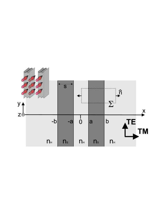
The physical configuration we consider in the present paper is shown in Fig.1: a pair of parallel dielectric slabs of thickness and refractive index separated by a distance and embedded in a host medium of lower refractive index . The axis is orthogonal to the slabs and light is assumed (without loss of generality) to be in a plane wave state propagating along . Under this assumption, the electric and magnetic fields can be written in the form:
| (1) | |||
| (2) |
being the wave number of the propagation along and the angular frequency. The dependence of the fields has disappeared thanks to the translational invariance of the system in the waveguide plane, and to the choice made for the direction of propagation. The general solution for the electromagnetic fields can be obtained as a linear combination of such plane waves.
Depending on the orientation of the fields with respect to the propagation direction, two independent electromagnetic polarizations states can be identified, known as Transverse Electric () and Transverse Magnetic () Marcuse ; Okamoto . The polarization state is characterized by , while the polarization is characterized by
For each polarization state, the field wavefunction is determined by solving the corresponding Maxwell equations. Since we are considering modes which are guided by the waveguide system, the electromagnetic field is confined in the slabs, where the wave-vector along the -direction is purely real , with . In the surrounding host medium the electromagnetic field is evanescent with a purely imaginary wave-vector .
For the polarizations, this is summarized in a field wavefunction (that is the or fields for the modes, respectively) which reads:
| (3) |
The system having reflection symmetry with respect to the plane, the electromagnetic modes can be classified as symmetric and antisymmetric depending on the symmetry operation of the field wavefunction, namely for the modes or for the ones. Note that this classification is related, but not identical to the usual one in terms of the reflection symmetry of the full electromagnetic field, where the magnetic field transforms as a pseudovector, while is instead a vector.
The dispersion relation connecting to , as well as a relation between the amplitude coefficients and the phases in the different regions are then obtained by matching the field (3) in the different regions according to the symmetry of the electric and magnetic fields. For the symmetric modes, the dispersion law has the following analytical, yet implicit form:
| TE | (4) | ||||
| TM | (5) |
for the polarizations, respectively. The dispersion laws for the anti-symmetric modes are obtained from the symmetric ones by replacing . In the following, we shall see that this fact holds for other physical quantities as well. In all these dispersion laws, the (integer) quantum number specifies the number of nodes of the wavefunction inside each slab.
In summary, the optical modes propagating along in a given two waveguide system are classified by their polarization state, the symmetric/anti-symmetric character of the field wavefunction with respect to reflections on the plane, and the number of nodes inside each waveguide. Thanks to the scaling properties of the Maxwell equations, the qualitative shape of the dispersion relations depends on the geometrical parameter only, which quantifies the ratio between the spacing and the thickness of each slab. The absolute value of fixes the natural frequency scale .
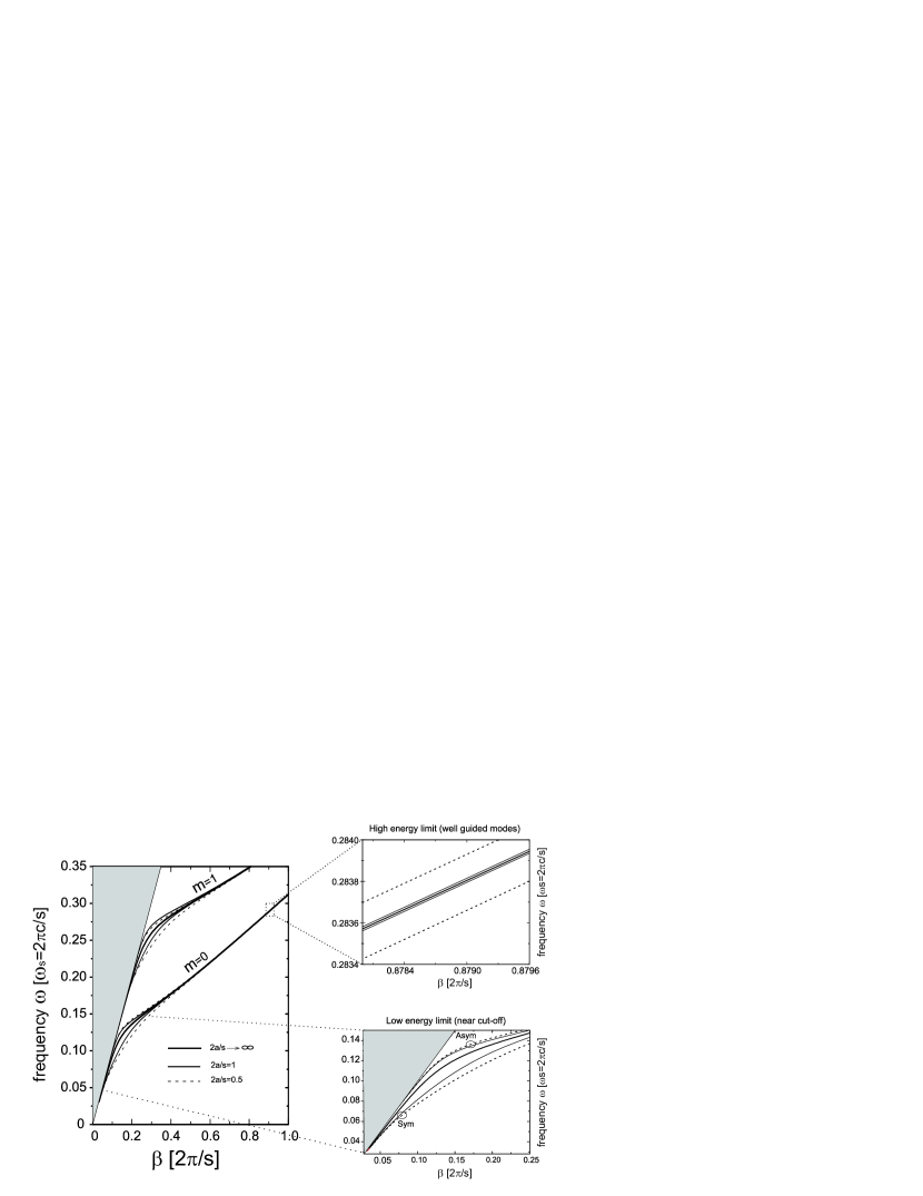
In Fig. 2, we have plotted the dispersion of the different modes (, symmetric and anti-symmetric) of the coupled slab waveguide system for different values of the geometrical parameter . All the branches have a lower cut-off to the frequencies that can actually propagate in a given mode of the coupled waveguide system. At the cut-off point, the waveguide dispersion coincides with the free photon dispersion of the host medium.
At infinite separation , the dispersion reduces to the one of an isolated waveguide, and for every polarization state the symmetric and anti-symmetric branches are degenerate. As the two waveguides are pushed closer, this degeneracy is lifted, and every branch experiences a frequency shift whose sign depends on its symmetric or anti-symmetric nature. As usual for the bonding/anti-bonding electronic states in diatomic molecules CCT_MQ , the symmetric states are pushed toward lower frequencies by the coupling, while the anti-symmetric ones are pushed toward higher frequencies. As a consequence, the cut-off frequency experiences itself a shift of the same sign and comparable magnitude.
In the next sections, we shall study the electromagnetic pressure acting on each of the two slab waveguides because of the presence of the other slab. The pressure being proportional to the intensity of light propagating along the waveguide system, it is important to relate the amplitude coefficient in (3) to the power density for unit length in the -direction. This is easily calculated from the flux of the Poynting vector through a planar section orthogonal to the propagation direction.
III Force between two planar waveguides
Starting from the electromagnetic field profiles discussed in the previous section, we shall now proceed with a calculation of the average electromagnetic force acting on the slabs when a monochromatic wave of frequency is propagating along the coupled waveguide system in a well-defined mode. To keep the treatment as simple as possible, we shall assume this force to be equilibrated by some other, unspecified, force which keeps the system at mechanical equilibrium at all times. The calculation of the force will then be performed in the framework of the macroscopic electrodynamics of continuous media using the Maxwell stress tensor Jackson ; LLFT . This technique allows one to directly calculate the force, and has been extensively used in the literature to estimate forces of electromagnetic origin in many contexts, from clusters of dielectric spheres Pendry to waveguides povinelli , to quantum fluctuations as in the Casimir effect LLCondMat . An important point of this formalism is that it does not make any assumption on the microscopic nature of the material media under examination and therefore can easily take into account absorption effects. In the following we shall focus our attention on the case of dielectric slabs with a real refraction index embedded in air, for which .
As all the fields have a monochromatic time dependence at frequency , momentum conservation arguments show that the average electromagnetic force acting on a body is equal to the surface integral of the time averaged Maxwell tensor
| (8) |
over an arbitrarily chosen closed surface enclosing the body with outward orientation:
| (9) |
In our specific configuration, a good choice for is the one shown in Fig.1b, that is a cylinder of axis parallel to and with rectangular bases parallel to the plane.
Thanks to the reflection symmetry of the whole set-up with respect to the plane, the component to the force vanishes . Also along the light propagation direction the force is zero, indeed as the geometry of the waveguide system is symmetric with respect to the plane, and the dielectric medium is non-absorbing , the combination of this reflection symmetry and the time-reversal is a symmetry of the problem. The electromagnetic force is therefore directed along the direction. The contribution of the two planar sides parallel to the plane cancel each other by translational symmetry, as well as the one of the two bases parallel to the plane. We are therefore left with the sides parallel to the plane; the component of the force due to these sides only involves the component of the Maxwell stress tensor; because of the translational symmetry of the configuration under examination, this quantity can only depend on the coordinate:
| (10) |
Inserting the explicit form of the fields, it is immediate to see that in the region external to the waveguide system. This is due to the evanescent wave character of the field in this region. The electromagnetic pressure (i.e., the force per unit length along and unit width along ) is therefore equal to evaluated in the region between the two waveguides, . Positive (negative) signs for respectively indicate repulsive (attractive) forces between the waveguides. Plugging in (10) the explicit expression of the fields found in the previous section (Sec. II), we obtain the following results for the symmetric modes:
| TE | (11) | ||||
| TM | (12) |
The expression for the antisymmetric modes are again found by replacing in (11) and (12). In the following, we will work at constant laser frequency and power density , so that the amplitude coefficients and have to be obtained by inverting (6) and (7).
Note that since the Maxwell stress tensor is bilinear in the local fields, the effect described here does not rely on the coherence of the light beam, thus the results of the present paper directly extend to the case of an incoherent, thermal source. Indeed the total pressure induced by a source with spectral distribution is simply , where is given by Eqs. (11) and (12).
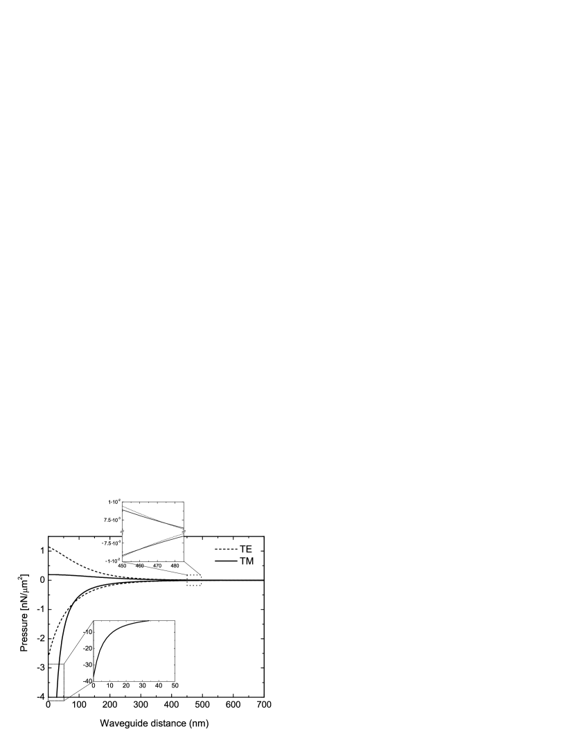
Regarding the monochromatic source, considered hereafter, one has to distinguish two cases, depending on whether the laser frequency is far from or close to the cut-off frequency of the considered mode. Results for the first case are shown in Figure 3 for the mode in nm thick silicon () waveguides: the pressure is plotted as a function of the separation between the waveguides. Fixed values are taken for the power density and the wavelength of the wave. The main feature is that the pressure is always attractive for both (continuous lines) and (dashed lines) symmetric modes, while it is repulsive for the spatially antisymmetric modes. Formally, this is an immediate consequence of (11) and (12), once one takes into account the fact that for guided modes . In magnitude, the force is a monotonically decreasing function of the separation . Physically, this behavior has an immediate explanation in terms of the analogy with two coupled well models: as shown in Fig.2, the frequency of the antisymmetric (symmetric) mode for a given monotonically grows (decreases) as the waveguides are brought closer.
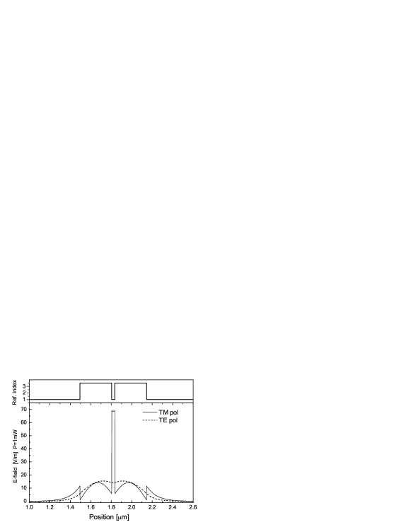
At large distances, the decay of the pressure as a function of distance is exponential and for a given polarization, the symmetric/anti-symmetric modes only differ by the sign of the pressure. Since the mode is more confined in the slabs than the one, it has a shorter characteristic length of the exponential. At short distances, it is interesting to note that the symmetric mode produces an significantly enhanced pressure as compared to the corresponding one. A physical explanation of this behavior is readily obtained by comparing the electric field profiles of the symmetric and modes, as shown in Fig.4: while the mode profile has a smooth spatial dependence, the one is strongly concentrated in the region between the two slabs. This feature is typical of modes Lipson , and originates from the continuity of the normal component of the electric displacement vector at the slab interface, which introduces a factor between the values of at the two sides of the interface.

If the laser frequency is not far from the cut-off of the mode, the dependence of the pressure on the separation is somehow richer. In Fig.5a we consider the case of a thicker waveguide . For the wavelength under consideration, all the modes up to are well confined, while we are just above the isolated () waveguide cut-off for the mode. Since the cut-off frequency of anti-symmetric modes increases for decreasing , it exists a cut-off separation below which light of the given wavelength ceases being guided in the mode. When from above, the spatial size of the mode diverges, and the field amplitude between the guides tends (for a given power density ) to zero. As a consequence, the pressure initially grows for decreasing , attains a maximum value at some separation value, and then goes back to zero as the cut-off separation is approached note . Clearly, the cut-off separation is larger for thinner waveguides (Fig.5b). This behavior can also be explained in terms of the two coupled well model: when the eigenstates of the independent wells are close to the continuum threshold, there exists a value of the distance (i.e., of the coupling strength), at which the antisymmetric state ceases to be bound and enters the continuum. On the other hand, for the tightly confined modes, the physics is qualitatively the same as in Fig.3.
IV Radiation induced deflection: the case of the air-bridge waveguide
Although the value of the radiation pressure obtained in the previous section might seem at a first glance rather small, it can have a observable effect in nanometric devices. In order to provide a quantitative estimate of such effects we consider the mechanical deflection induced by the optical force on an air-bridge double slab waveguide system made of two thin silicon slabs of length whose opposite edges are clamped to the substrate. Such a device can be realized, e.g., via chemical etching technique in sacrificiallayer .
The deflection induced by the radiation pressure on the device can be evaluated using the Euler-Bernoulli beam equation LandauElastic
| (13) |
where, is the separation between the slabs, is the Young modulus, and is the area moment of inertia of the slab’s cross section, whose width and thickness are and . The maximum deflection induced on each silicon (GPa) slab by a power at a wavelength m propagating in the TM symmetric mode is shown in Fig.(6) as a function of the initial separation for three different values of the slab length m, and for slab’s thickness nm. For this parameter choice, a linearized treatment of Eq.(13) around the initial slab distance already provides accurate results.
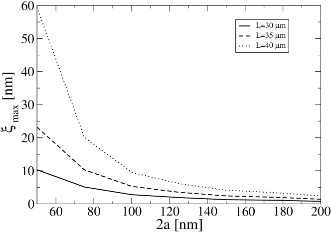
From figure (6) one can see that the maximal value of the deflection induced by the optical force can reach the values of tens nanometers for reasonable structural parameters: slabs lengths mm (the deflection is strongly sensitive to ), and waveguides separations nmnm. Such deflections are of the same order of previous investigations made for different configurations povinelli and are accessible to standard Atomic Force Microscope techniques AFM . As a final remark, as the pressure is roughly speaking inversely proportional to the group velocity of the mode, one expects that the radiation pressure, and hence the mechanical deflection, can be enhanced if the is slowed down by a longitudinal modulation of the structure as in coupled resonator optical waveguides CROW .
V Large and small distance behavior
In this section we derive the asymptotic behavior of the pressure for small and large slab separation, which provides a deeper insight on the findings of the previous section.
V.1 Large distance behavior
For large separation , the force has the typical exponential decay of two-well systems in the tight-binding limit. As long as the modes are confined, the general qualitative trend is that the larger the characteristic length , the larger the field in between the slabs and consequently the stronger the force. More specifically: for a given order the pressure is (slightly) stronger for the mode than for the corresponding one. (ii) The pressure is stronger for higher modes.
V.2 Small distance behavior
In order to get some analytical insight in the small distance regime, it is useful to expand all the waveguide parameters in powers of the slab separation , while keeping and constant. Let us consider the specific case of . The zeroth order is the wave number of the propagation along a single waveguide of double thickness , and has to be calculated from the dispersion laws once the hyperbolic tangent is replaced by its limiting value and the doubled thickness is taken into account as . The first order term is given, e.g., for symmetric modes by:
| TE | (16) | ||||
| TM | (17) |
Note that is negative for all modes, indicating that the force is attractive. Along the same lines, analytical expansions can be obtained for the pressure . The value for the symmetric modes has the form
| (18) | |||
| (19) |
Analogous algebra leads to the corresponding expressions for the anti-symmetric modes, which have the form:
| (20) | |||
| (21) |
Starting from these formulas, a physical explanation can be provided for the remarkable facts observed in Fig.2 for the modes, namely the suppressed value of the force for the anti-symmetric mode and the enhanced value for the symmetric mode with respect to the modes. As long as we are considering well confined modes, the ’s of all modes have almost comparable values, somewhat larger than the ’s. This explains the general fact that the force is about a factor weaker for the antisymmetric mode than for the corresponding symmetric one. The behavior for the modes can be explained starting from the value of the refractive index, which is significantly larger than : thanks to the in the denominator, the force for the antisymmetric mode is dramatically suppressed of a factor (for the chosen value of the refractive index) with respect to the one for the symmetric mode. For similar reasons, the force is enhanced of a factor over because of the ’s in the denominator (see Fig. 3).
VI Conclusions
In conclusion, we have performed an analytical study of the optical forces appearing between a pair of parallel slab waveguides when light is propagating through them. Depending on the spatial symmetry of the mode wavefunction, the sign of the force can be either attractive or repulsive. The dependence of the force as a function of the separation between the slabs has been characterized for the different polarization states, and analytical expressions have been obtained for both the large and the small distance limits. A strong enhancement of the force has been identified for the symmetric mode, as well as a suppression for the antisymmetric one. Simple physical explanations have been provided for these features. A quantitative study for typical air-bridge configurations confirms that the mechanical deflection of the structure induced by the optical force can be measured by standard Atomic Force Microscopy techniques.
VII Acknowledgment
We thank L. P. Pitaevskii and D.S. Wiersma for useful discussions and we acknowledge support by the Ministero dell’Istruzione, dell’Università e della Ricerca (MIUR).
References
- (1) I. Wilson-Rae, P. Zoller, and A. Imamoglu, Phys. Rev. Lett. 92, 075507 (2004).
- (2) P. C. Chaumet and M. Nieto-Vesperinas, Phys. Rev. B 62, 11185 (2000); P. C. Chaumet and M. Nieto-Vesperinas, Phys. Rev. B 61, 14119 (2000); P. C. Chaumet and M. Nieto-Vesperinas, Phys. Rev. B 64, 035422 (2001); M. Bayindir, C. Kural, E. Ozbay, J. Opt. A Pure and Applied Optics 3, S184 (2001); M. L. Povinelli, M. Ibanescu, S. G. Johnson, and J. D. Joannopoulos, Appl. Phys. Lett. 85, 1466 (2004); R. Gómez-Medina and J. J. Sáenz, Phys. Rev. Lett. 93, 243602 (2004); M. L. Povinelli, S. G. Johnson, M. Loncar, M. Ibanescu, E. J. Smythe, F. Capasso, J. D. Joannopoulos, Opt. Exp. 13, 8286 (2005); A. Mizrahi and L. Schächter, Phys. Rev. E 74, 036504 (2006).
- (3) M. Notomi, H. Taniyama, S. Mitsugi, and E. Kuramochi, Phys. Rev. Lett. 97, 023903 (2006).
- (4) M. L. Povinelli, M. Loncar, M. Ibanescu, E. J. Smythe, S. G. Johnson, F. Capasso and J. D. Joannopoulos, Opt. Lett. 30, 3042 (2005).
- (5) D. Marcuse, Light Transmission Optics (New York: Van Nostrand Reinhold, 1972), and Theory of Dielectric Optical Wave Guides (New York, Academic Press, 1974)
- (6) K. Okamoto, Fundamentals of optical waveguides, (Academic Press, 2000)
- (7) C. Cohen-Tannoudji, B. Diu, F. Laloë, Quantum mechanics (Wiley-Interscience, 1977).
- (8) J. D. Jackson, Classical Electrodynamics, (Wiley, 1998)
- (9) L. D. Landau and E. M. Lifshitz, The classical theory of fields (Pergamon Press, Oxford, 1975).
- (10) M.I. Antonoyiannakis and J. B. Pendry, Phys. Rev. B 60, 2363 (1999).
- (11) L. D. Landau, E. M. Lifshitz, L.P. Pitaevskii, Statistical mechanics Vol.II: Theory of the condensed state (Pergamon Press, Oxford, 1980), chap.VIII
- (12) V. R. Almeida, Q. Xu, C. A. Barrios, M. Lipson, Opt. Lett. 29, 1209 (2004); Q. Xu, V. R. Almeida, R. R. Panepucci, M. Lipson 29, 1626 (2004).
- (13) Note that this non-monotonic behavior has a completely different origin from the one reported in povinelli . There, a pair of linear waveguides were considered instead of slab ones, and the change of sign of the pressure for the antisymmetric TE mode was due to edge effects because of the confinement in the direction.
- (14) L. D. Landau and E. M. Lifshitz, Theory of Elasticity (Pergamon Press, Oxford, 1970).
- (15) S. Iwamoto et al., App. Phys. Lett. 88, 011104 (2006).
- (16) A. San Paulo et al., App. Phys. Lett. 87, 053111 (2005).
- (17) J. Scheuer, G. T. Paloczi, J. K. S. Poon and A. Yariv, Opt. Photonics News 16, 36 (2005).