The Nylon Scintillator Containment Vessels for the Borexino Solar Neutrino Experiment
Abstract
Borexino is a solar neutrino experiment designed to observe the 0.86 MeV 7Be neutrinos emitted in the pp cycle of the sun. Neutrinos will be detected by their elastic scattering on electrons in 100 tons of liquid scintillator. The neutrino event rate in the scintillator is expected to be low (0.35 events per day per ton), and the signals will be at energies below 1.5 MeV, where background from natural radioactivity is prominent. Scintillation light produced by the recoil electrons is observed by an array of 2240 photomultiplier tubes. Because of the intrinsic radioactive contaminants in these PMTs, the liquid scintillator is shielded from them by a thick barrier of buffer fluid. A spherical vessel made of thin nylon film contains the scintillator, separating it from the surrounding buffer. The buffer region itself is divided into two concentric shells by a second nylon vessel in order to prevent inward diffusion of radon atoms. The radioactive background requirements for Borexino are challenging to meet, especially for the scintillator and these nylon vessels. Besides meeting requirements for low radioactivity, the nylon vessels must also satisfy requirements for mechanical, optical, and chemical properties. The present paper describes the research and development, construction, and installation of the nylon vessels for the Borexino experiment.
keywords:
Borexino , solar neutrinos , nylon , organic scintillator , low-backgroundPACS:
29.40.Mc , 26.65.+t , 81.05.Lg, , ††thanks: Now at Massachusetts Institute of Technology, Cambridge, MA, USA , , , ††thanks: Now at Kingsley, MI, USA , ††thanks: Now at SNOLab, Sudbury, ON, Canada , , , ††thanks: Now at Lockheed Martin Corporation, Sunnyvale, CA, USA , , , , , , , , ††thanks: Now at Stanford University, Stanford, CA, USA , ††thanks: Now at Case Western Reserve University, Cleveland, OH, USA , ††thanks: Now at University of Chicago, Chicago, IL, USA ††thanks: Now at Virginia Polytechnic Institute, VA, USA
1 Introduction and Overview of the Borexino Experiment
Borexino [1] is a liquid scintillation detector designed to observe solar neutrinos. It is located 1.4 km (3500 meters water equivalent) underground, in the Gran Sasso National Laboratory in Italy. The goals of the project are two-fold: to confirm that the sun produces energy in accord with the Standard Solar Model [2] through the series of neutrino-yielding nuclear fusion reactions known as the cycle, and to use the sun as a powerful source of neutrinos to study the phenomena of neutrino oscillations [3, 4]. The main observational target of the detector is the monoenergetic ( keV) 7Be neutrinos that are believed to make up roughly 10% of the total solar neutrino flux [2]. However, the possibility of observing the much less common neutrinos ( MeV) is also foreseen [5].
Borexino will directly observe only the electrons scattered by these neutrinos, not the total neutrino energy. Hence the observed energy spectrum for each type of neutrino will consist of a nearly flat signal ending at a shoulder, at 667 keV for the 7Be neutrinos and 1.22 MeV for the neutrinos. For this reason, the two important energy regions for the detector are the main neutrino window (NW) of 250–800 keV, and the window from 800–1300 keV. The main window has a lower limit of 250 keV due to the unavoidable presence of 14C, a keV -emitter, in organic material. The chosen windows extend beyond the nominal spectra endpoints due to the finite energy resolution of the detector. The Borexino experiment is made challenging by the fact that many naturally-occurring radioactive isotopes can decay to produce signals in these energy windows.
The active component of the Borexino detector (Figure 1) is a spherical shielded mass of slightly under 300 tons of liquid scintillator. When a neutrino scatters from an electron in the scintillator, the recoil of the electron induces light emission in the material. The main component of the scintillator is pseudocumene, an aromatic solvent (1,2,4 trimethyl benzene) that emits light in the ultraviolet at nm. The fluorescent dye PPO (2,5-diphenyl oxazole) was selected [6] as a pseudocumene additive at 1.5 g/liter. Energy is transferred in a fast, non-photonic manner from pseudocumene to PPO molecules. PPO acts as a wavelength shifter: because it has a large Stokes shift between its absorption (290 nm) and emission (380 nm) wavelengths, it greatly reduces re-absorption of the emitted light, lengthening the optical attenuation length to 7 m. Scintillation light is detected by an array of 2240 eight-inch, model ETL 9351 photomultiplier detectors [7], most equipped with light collectors [8, 9] to enhance their optical coverage. The phototubes are fixed to the inner surface of a 13.7-m diameter stainless steel sphere centered on the active portion of the detector.
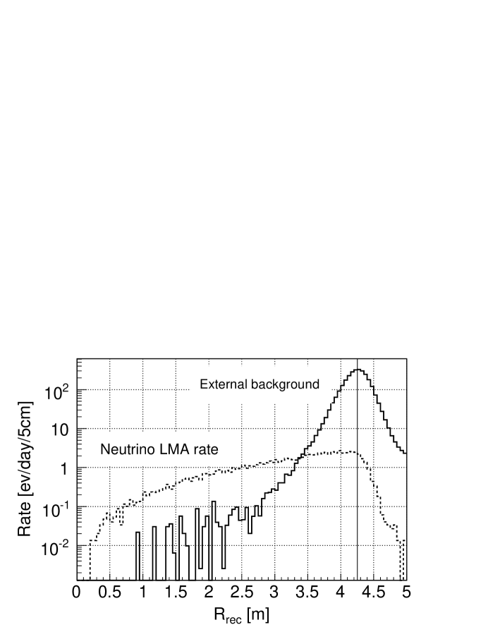
The design of the Borexino detector is based on the principle of graded shielding: traveling inward to the center, each component is protected from external radiation by the preceding one. To reduce external radioactive background (mainly inward-bound rays from various outer portions of the detector) contaminating the data sample of neutrino-induced scintillation events, data will be analyzed primarily from the central scintillator volume of diameter 6 m (having a mass of 100 tons), considered to be the fiducial volume of the detector.111A scintillation event may be determined to have occurred within or outside the fiducial volume via methods of position reconstruction that use timing information from the phototubes [10, 11]. The expected rate of 7Be neutrino events in the main neutrino window within this fiducial volume is per day. (A few additional events per day from and CNO neutrinos will also be seen in this energy window.) The size of the fiducial volume may be changed as necessary by trivial adjustments to data analysis software. All 300 tons of scintillator are contained by a transparent spherical nylon vessel, the so-called inner vessel, with an 8.5 m diameter.
A passive buffer region outside the inner vessel shields the scintillator from the radioactivity of the photomultiplier tubes and the stainless steel sphere. If the scintillator were in contact with these components, which are relatively high in radioactivity, the rate of events would overwhelm the data acquisition system. The buffer fluid consists of pseudocumene with an added component (dimethyl phthalate or DMP [12] at 5 g/liter) that quenches scintillation: the optical attenuation length for scintillation events in the buffer is only about 20 cm. Events in the buffer are therefore detected by no more than a few photomultiplier tubes, and are easily discriminated from neutrino events that occur in the scintillator fluid. We note that the pseudocumene and DMP mixture has nearly the same density as the scintillator [13]. Thus the choice of scintillator and buffer materials results in a near buoyancy-free environment for the scintillator, permitting the use of a thin membrane for the nylon vessel.
A second nylon vessel of diameter 11 m, the outer vessel, divides the buffer fluid into inner and outer regions in order to prevent radioactive impurities (radon, dust) from approaching the inner vessel. The volume of buffer fluid outside the outer vessel is contained by the stainless steel sphere. Beyond the stainless steel sphere is an outer steel tank filled with an ultra-pure water buffer; this is used as an active muon veto system and as a passive shield against neutrons from the rock walls of the laboratory.
The Borexino detector is extremely sensitive to backgrounds from trace quantities of radioactive impurities that occur in dust and within detector materials (238U and 232Th decay chains and 40K) and in air (39Ar, 85Kr, and 222Rn and its daughters). In addition to providing methods for removing such impurities from the scintillator, great care must be exercised to avoid contamination during fabrication and handling of critical components of the detector. In particular, because of their close proximity to the sensitive part of the detector, the nylon vessels require careful selection of materials and clean procedures for fabrication and handling. The vessels are also rather delicate and must be maintained within particular ranges of humidity, temperature, and differential pressure in which the membrane stress levels are acceptable.
2 The Design Requirements for the Vessels
We first must point out that the choice to use two flexible, thin nylon vessels in the Borexino experiment is not obviously the only feasible option. Previous neutrino detectors, both Čerenkov (e. g., SNO [14]) and scintillator-based (e. g., CHOOZ [15] and Palo Verde [16]), have used a single rigid, transparent, thick-walled acrylic vessel for liquid containment. A rigid vessel has several advantages: it can be self-supporting (no complex support structure is required); it has a fixed, well-known volume, minimizing systematic uncertainties in the target mass; and because of its rigidity, precise control over the internal and external liquid levels is not necessary during initial filling of the detector.
Despite these advantages, other considerations made it difficult to choose a rigid vessel design. Common rigid plastics such as acrylic and polycarbonate are not chemically compatible with the pseudocumene scintillator. Even more importantly in our case, the low rate of radioactive background tolerable in Borexino causes the thick walls of a rigid vessel to become a liability. Since solid materials cannot be purified to the same standards as the liquid scintillator or the passive buffer, the scintillator containment vessel, if it is too massive, can contribute disproportionately to the number of radioactive background events (particularly rays) seen in the fiducial volume of the detector. This led us to opt for a thin-membrane design, which has the added benefit of greater optical clarity. Thin-membrane vessels also have the advantage of being possible to construct in a controlled (clean room) environment, unlike a rigid acrylic vessel, which would need to be built on-site.
Once thin membranes are selected, a number of other design constraints appear. Not only does an inner vessel (IV) contain the scintillator, but in addition a second outer vessel (OV) surrounds it. The OV divides the buffer fluid into two concentric volumes, in order to act as a barrier toward radon gas and to keep any particulate remaining within the Stainless Steel Sphere well away from the scintillator fluid. However, this nesting of two vessels complicates the design further. Systems are needed to keep the vessels stationary under the influence of buoyant or gravitational forces, due to potentially different densities (resulting from composition or temperature differences) in the three separate fluid volumes. These are provided in Borexino by sets of ropes enveloping the vessels like hot-air balloons. Rigid nylon rings, or “end caps,” at the polar regions (top and bottom of the detector), two for each vessel, serve as fixed attachment points for the vessel membranes. Tubes passing through the end caps allow insertion and removal of fluids. The end caps and tube assemblies also act as sites for attachment of monitoring instruments and the ends of the rope systems.
As opposed to a rigid vessel design, the vessels themselves cannot support significant weight or buoyant forces. All such forces are transferred, through the system of ropes and end caps, into the external stainless steel sphere (SSS); the vessels and sphere work as an integrated design. The region outside the SSS is a buffer of ultra-pure water, so it is necessary to ensure that the lower-density volume contained by the SSS does not float upward. Engineering of the sphere to handle these loads is straightforward: the SSS is affixed by several legs and pads to the bottom of the outermost steel tank. The sphere doubles as a support mechanism for all the internal phototubes.
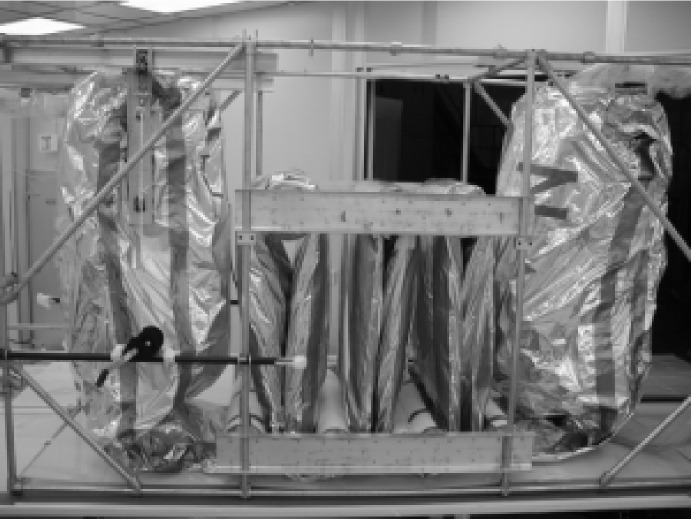
Although the thin-membrane vessels of Borexino were not installed into the detector and inflated to their final spherical shapes until spring 2003, they have been an integral part of the Borexino experimental design since the initial proposal was submitted in 1991 [17]. A 4-ton prototype of the thin-membrane design, the Counting Test Facility, has been operated successfully since 1995 [18]. A full-scale mock-up of the nested Borexino vessels has also been constructed and inflated at Princeton University [13, 19, 20]; see Figure 2. Since the initial Borexino proposal, the concept has been incorporated in other full-scale experiments as well. For instance, the reactor neutrino detector KamLAND uses a thin-membrane scintillator containment vessel [21]. Although it has no second vessel analogous to the Borexino OV for restricting the inward flow of radon, KamLAND does have thin membranes in front of its photomultiplier tubes to act as a radon barrier.
The fundamental requirements of the Borexino experiment for the IV and OV are summarized below. The vessels must be able to survive their environments:
-
a)
Chemical resistance. The vessels must be chemically compatible with the scintillator (pseudocumene and PPO) and buffer (pseudocumene and DMP); with pure water; and of course with normal air, in which they were constructed and with which they were initially inflated. For Borexino, the selected filling strategy involved filling the inner detector (i. e., everything inside the SSS) first with water, then later with the scintillator and buffer fluids.
-
b)
Mechanical strength. The vessels must withstand the expected membrane stresses due to buoyant forces that occur during filling and steady-state operations. By design they should also be able to withstand, at least for long enough to correct the situation, stresses up to 20 MPa that could occur as a result of 5∘C temperature differences (which would cause 0.4% density differences) between any of the three fluid volumes. The expected stresses are calculated by a finite element analysis, discussed below in section 4.7. Finally, they must survive repeated handling during installation and inflation operations that could lead to crack formation (brittle failure mode).
The vessels must in addition not hinder the operation of the experiment:
-
c)
Optical transparency. The vessels must be transparent and free of haze for the blue and near-UV light emitted by the scintillator (350–450 nm). They must also have an index of refraction similar to that of pseudocumene. This minimizes refraction of scintillation light at the vessel and reflection of light from the nylon-scintillator interface, both of which could interfere with an accurate position reconstruction of scintillation events. The extents to which nylon films meet this requirement and the two previous ones are described in section 3.2 below.
-
d)
Low intrinsic radioactivity. The levels of U, Th, and K in the scintillator vessel must be low to minimize background due to gamma rays that originate in the vessel. (Potassium is an issue due to the long-lived, naturally occurring radioactive isotope 40K, which occurs in natural potassium with an isotopic abundance of 120 ppm.) In addition, emanation of 222Rn gas due to intrinsic 226Ra in the nylon must be low. The desired requirement is that the vessels contribute fewer than one radioactive event per day in the 7Be neutrino energy window within the fiducial volume. The intrinsic background activities in the nylon film are described towards the end of section 3.2, while the repercussions for Borexino are discussed further in section 6.2.2.
-
e)
Clean fabrication. Fabrication of the vessels (cutting of panel sections, bonding of joints, packaging, etc.) must be done in clean conditions, as we describe in section 4, to minimize backgrounds due to dust: the tolerable amount of dust within the IV is no more than 3 mg. Also, deposition of radon daughters on the vessel surfaces must be kept to an absolute minimum. It is worth noting that even before the detector was operational, for instance during the transportation and installation of the Borexino vessels at LNGS, the OV was helping to protect the IV from dust and radon exposure.
Finally, the vessels must be effective at fulfilling the goals for which they were designed:
-
f)
Low permeability. To minimize backgrounds due to diffusion of 222Rn from the buffer through the vessel into the scintillator, the membrane must have a low permeability to radon. In brief, the film must be impermeable enough (and thick enough) that the average time required for a radon atom to diffuse through the entire film is comparable to or greater than the mean life of radon, 5.516 days. The permeability of nylon to radon atoms is described in section 6.2.1.
-
g)
Leak tightness. The vessels, the IV in particular, must be leak tight enough to prevent any significant mixing between the scintillator and the buffer fluids during the lifetime of the experiment. We state the leak tightness requirements in section 4.6, and report measured values there and in section 5.3.2.
-
h)
Monitoring. The vessels must be outfitted with instrumentation that permits monitoring the temperatures and pressures of the scintillator and buffer fluids, as well as the current shapes and positions of the vessels themselves. The monitoring instrumentation is described in section 4.5.
Note that requirements a), b), c), d) and f) above are mainly or entirely a function of the material chosen for the vessels, rather than the method of fabrication or the supporting infrastructure.
3 Production and Selection of Nylon Film
Thin nylon film can meet all requirements for the vessels and was thus the chosen material. However, standard commercially available films are not produced under sufficiently clean conditions. To achieve the desired properties and level of cleanliness, the film was therefore extruded under appropriate conditions and from raw materials that were carefully selected such that the material meets the size, purity, optical clarity, and cleanliness required for Borexino. Some details of the properties of the materials and of the vessel fabrication sequence are summarized below and in the following section.
3.1 Production of the nylon film
The term nylon, as described in great detail in [22] (for instance), refers to a family of polymers built from carboxylic acid, amine, and/or amino acid monomers. Nylons may be characterized in numerous ways, the most obvious being by the chemical formula of the monomers (the candidate materials for Borexino were all based on nylon-6, H-[HN(CH2)5CO]n-OH). To produce a thin nylon film, polymer pellets are heated above their melting point (to around 250∘C), yielding a melt that is extruded at high pressure. Rapid cooling afterwards ensures that the polymer chains remain in a transparent amorphous state rather than developing a hazy crystalline structure.
Several types of pellets were initially under consideration for use in the Borexino vessel material. The two final candidates, selected mainly due to radiopurity considerations, included Capron B73ZP pellets made by AlliedSignal/Honeywell [23], and Sniamid ADS40T pellets manufactured by Nyltech. (Since then, the Capron product line has been acquired by BASF [24], and the Sniamid line by Rhodia Engineering Plastics [25].) Capron B73ZP consists of pure nylon-6 polymer chains, while Sniamid ADS40T is a nylon-6 based co-polymer (i. e., its polymer chains contain more than one type of monomer) with a proprietary formula.
Nylon film produced from Sniamid pellets proved to be slightly brittle, however; an additive was required for pliability. The selected additive was Ultramid B4, another pure nylon-6 polymer manufactured by BASF [24]. Sniamid and Ultramid pellets were mixed in a 5:1 ratio, upon extrusion yielding a film that will also be referred to as Sniamid.
3.1.1 Radiopurity levels of the nylon pellets
We set a radiopurity target of 1 part per trillion (ppt) by mass of uranium in the pellets and the film for the inner vessel; anything less than or equal to 5 ppt was also considered acceptable, since it would not affect Borexino’s sensitivity to 7Be solar neutrinos. Efforts were made to measure the 238U in the pellets which are extruded to make the film. These measurements were carried out by Tama Chemicals [26] with inductively coupled mass spectroscopy on samples of nylon digested in ultrapure acids.
The Capron B73ZP was measured in this way to have contamination levels of 0.46 ppt U by mass and 1.1 ppt Th [27]. Tama Chemicals found the Sniamid pellet levels to be 1.1 ppt U and 1.6 ppt Th. (Errors were all .) At this point, therefore, the Capron B73ZP pellets appeared to have a slight advantage. Measurements of the pellet potassium contamination (all isotopes) using neutron activation analysis and graphite furnace atomic absorption spectroscopy at various facilities gave inconsistent results, in the range 13–25 ppb for Capron pellets and 1.6–25 ppb for Sniamid pellets [27]. All of these measurements were difficult and subject to contamination. Fortunately, the most important values, the radon emanation rates of the final extruded films, could be measured directly, and were found to be satisfactory (Section 3.2.4).
The Ultramid pellet contaminant levels are not directly known, since the need to include this additional component in the Sniamid-based film was not realized until after the pellet radiopurity measurement campaign. In any case, the Sniamid film was thought of as a backup material at this point.
3.1.2 The nylon film extrusion process
The process of extrusion takes nylon pellets in raw form and converts them into flat sheets. The thickness requirements for the Borexino vessels are chosen as a compromise between increased thickness, for mechanical strength and reduction of radon diffusion; and reduced thickness, for flexibility (which minimizes the likelihood of cracking) and reduction of the total radioactive decay rate by minimization of the vessel masses. In addition, we needed sheets that were as wide as possible, in order to minimize the number of panels from which each vessel would have to be constructed. Sheets with a thickness of 125 m and width of about 122 cm (4 ft.) were selected. The thickness was measured during extrusion and has a tolerance of m. It should be noted that the thickness is greater than that of typical commercially produced, food-grade nylon film. The width of 4 ft. is more or less the maximum available on the market.
The candidate nylon films (“Capron,” generated from pure Capron B73ZP pellets, and “Sniamid,” produced from the Sniamid ADS40T pellets and Ultramid B4 pellets in a 5:1 ratio) were extruded at two separate facilities. Capron film was produced at an AlliedSignal/Honeywell plant in Pottsville, Pennsylvania, USA, in 2001. Sniamid film was extruded at the mf-folien plant [28] in Kempten, Germany, later that year. The two plants are among the few possessing an extrusion apparatus suited for producing wide panels of such thickness under relatively clean conditions. The temperature and rate of extrusion at both facilities were closely monitored and optimized to ensure the crucial property of low haze levels ( scattering of incident light) in the newly extruded nylon film.
3.1.3 Pre-cleaning of the nylon film
The inner surface of the inner vessel must satisfy very strict particulate contamination standards due to the relatively high levels of U, Th, and K in dust. Particles deposited on the nylon film could end up in the scintillator fluid, contributing high levels of background in the detector. It was estimated that, assuming 1 ppm U and Th concentrations in generic particulate, a surface cleanliness level of 50 as defined by US military standard 1246-C (at most one particle with a 50 m diameter per square foot [29]) is required. In other words, under these assumptions, only 3 mg of dust are tolerable on the inside surface of the entire inner vessel.
All nylon film used for both inner and outer vessels was precision cleaned and certified at level 25 by CleanFilm Inc., New York, USA. Cleaning used a non-contact, ultrasonic disruption technique to loosen particles that were then removed from the surface by negative pressure. The cleaned nylon rolls were double-bagged with thin, commercially available class-25 nylon film, and covered with an aluminized layer to minimize inward radon diffusion during shipping and storage. The first few external layers of each roll were discarded during fabrication. All film used to cover the vessel panels during vessel assembly and shipping was also certified to level 25 (refer to section 4.2).
3.2 Selection of the nylon film
Several factors were considered in the selection of the particular nylon material for the vessel, many of which, such as low radon emanation, are not standard tabulated data. A program of specific measurements was therefore carried out to characterize and select the final envelope material.
3.2.1 Chemical compatibility
The mechanical properties of dry nylon film are thought to be essentially unchanged after immersion in pure water-free pseudocumene, scintillator fluid (pseudocumene with added PPO), and buffer fluid (pseudocumene with added DMP). Tests of the material properties (tensile strength , and Young’s modulus ) of Capron film immersed in pure pseudocumene, in equilibrium with air at relative humidities varying from 0–60%, show essentially no difference from Capron film in air at the same relative humidities [30]. Although an earlier program of tests showed some variation in the material properties of nylon immersed in pure pseudocumene, scintillator, or buffer fluid compared with nylon in a dry N2 atmosphere [19], it is believed that this variation resulted from traces of water present in the respective liquids. Samples of various nylon films immersed in any of these liquids that were kept in a tightly sealed jar for three months, or in a liquid to which silica gel was added (to absorb water), showed no significant difference in their tensile strength or Young’s modulus from samples in a dry nitrogen atmosphere [19].
An important concern is the effect of water on the nylon film over periods of several months, as in the water-filling stage of Borexino. The Young’s modulus of nylon in contact with water (even when immersed in another fluid that is saturated with water) is reduced due to plasticizing—hydrogen bonds form between water molecules and polymer chains in place of hydrogen bond crosslinks between chains. However, the effect is found to be reversible, even after the film is soaked in room-temperature water for one month [19]. Tests have shown that nylon films come to equilibrium with the relative humidity of the surrounding environment within a few days.
Nylon film that has been soaked in water and then allowed to dry again exhibits a milky white haze on its surface. This is thought to be a layer of nylon monomers leached from the material by the water and then deposited on the surface. The monomer is initially present throughout the nylon; it diffuses over time, especially when the nylon is humidified. This layer of monomer can be washed away by another immersion in water or even in pseudocumene.
Water can also cause hydrolysis in nylon. This is the reverse of the polymerization reaction, compromising the nylon molecular structure, but it only happens on time scales that are long compared to the expected period of several months for the Borexino water filling. In particular, the Young’s modulus of a nylon-66 sample, chemically similar to the nylon-6 based materials used in Borexino, is drastically reduced when it is maintained in a 100% relative-humidity environment for 2 months at 66∘C [31]. An extrapolation from data at 66∘, 82∘ and 93∘ [31] to the much lower operational temperature in Borexino (C) gives an estimated time scale of 10 years for significant degradation to occur [19]. Thermodynamic arguments yield similar time frames [32].
3.2.2 Mechanical measurements
Polymer materials in general have a glass transition temperature , at which a second-order phase transition occurs, that depends upon the exact composition of the material [33]. Above , the material is in a “plastic state” which is pliable and, if stretched, may be permanently deformed. At lower temperatures, a “glassy state” has a greater Young’s modulus, but is more brittle and breaks at lower strain. Notably, the presence of water (higher relative humidity) decreases the value of from that for a dry polymer. Hence at constant temperature between the minimum and maximum possible values for , nylon film in a humid environment is likely in the plastic state, while dry nylon is in the glassy state. During construction and installation of the Borexino vessels, a high humidity was maintained to prevent brittle failure. Once the vessels are filled with scintillator and buffer fluids and are being maintained in a static condition in their preferred spherical shape, the humidity of their environment will be lowered in order to take advantage of the higher tensile strength and Young’s modulus.
A series of mechanical tests was performed on Capron and Sniamid film, in order to measure their material properties as functions of relative humidity, holding the temperature constant at 22∘C [30]. For each individual sample, a Tinius-Olsen machine was used to graph the stress on the sample as a function of its fractional elongation (strain) . Typical stress-strain relationships for the film are shown in Figure 3. The stress is approximately linear with strain, , and the film behaves elastically according to Hooke’s Law nearly up to the yield point. At stresses beyond the yield point, the material is irreversibly damaged. Film in the plastic state, above , undergoes viscous deformation, elongating to several times its original length. Film in the glassy state, below , elongates much less and then breaks.
The Young’s modulus values at room temperature are 1.7 GPa when the film is dry, and 0.4 GPa for wet film at 100% relative humidity [30]. With 125 m-thick film, typical values at room temperature for the membrane stress at the yield point are 70–80 MPa and MPa for dry and wet conditions, respectively. These values are similar for Capron and Sniamid films, although Sniamid is a little stronger at all humidities and appears to transition from the glassy to the plastic state at a slightly higher relative humidity.
Another factor to consider is creep, an irreversible stretching of the film when a constant stress is continually applied over a long period of time. At room temperature, creep at a stress level of 5 MPa for typical nylon films is 0.5%, 3%, and 7% under dry, 20% relative humidity, and wet conditions, respectively [19]. The Borexino design will maintain stress levels of 10% of the yield stress. As small creep-induced elongations occur at localized stress hot spots, operational stress levels will naturally be minimized.
The other possible failure mode of nylon film is brittle failure, in which nylon that is folded back upon itself, forming a crease or point, develops a crack or pinhole. Only the glassy state of the film is susceptible to cracking, the plastic state being much more pliable. This was nevertheless a concern because large cracks developed in the nylon film of the second Borexino prototype, the Counting Test Facility (CTF 2), while it was exposed to a dry nitrogen atmosphere. Because of this event, further tests were performed on the nylon films to simulate the rough treatment and possible brittle failures that could happen during shipment and inflation of the Borexino vessels. Inflatable nylon packets made of two 28 cm circles of film sealed at the edges were produced. Packets at different humidities were repeatedly inflated and deflated. The deflation step created severe wrinkles in the film and joint that reappeared at every cycle in the same spots. The packets were tested for leaks after each cycle. Dry packets typically failed after 20 cycles; the time to failure more than doubled at 40% relative humidity. Capron film packets tended to survive longer than those constructed from Sniamid [30]. In any event, the Borexino film, being only 25% the thickness of that used in the Counting Test Facility, should be much less susceptible to cracking.
3.2.3 Optical measurements
Among other reasons, one good argument in favor of the use of nylon film for the scintillator containment vessels is that the index of refraction of nylon-6 at near-UV wavelengths is 1.53. Since this is so near the value of for pseudocumene, reflection and refraction of scintillation light from the vessels will be a negligible problem.
Nylon film can be produced with excellent light transmittance and low haze properties. Such characteristics minimize scattering and loss of photons as they travel to the photomultiplier tubes. These conditions are essential for accurate energy measurement, good energy resolution, and precise position reconstruction of the events.
Capron and other non-amorphous nylon polymers tend to be slightly hazy at the 0.1 mm thickness required for the vessel. This issue was resolved by rapid quenching of the Capron film during its extrusion, preventing the development of crystallization that tends to cause this haziness. The amorphous co-polymer nylons such as Sniamid are by nature very clear optically. The nylon films selected for Borexino both show transmittance in pseudocumene above 300 nm and less than 1% scattering at angles greater than 70∘ with 366 nm light [19]. The Capron film was measured during extrusion to have an average haze level of 0.5%, much lower than the required 1.5%.
3.2.4 Radioactivity requirements and measurements
Part of the duty of the Borexino vessels is to act as barriers to the inward travel of radon gas. Diffusion of radon through nylon film should be low—both to reduce emanation of radon from intrinsic 226Ra in the material, and to slow the transport of external contaminants. As we discuss in more detail in section 6.2.1, the permeability of nylon to radon atoms increases rapidly with humidity; this fact must be balanced against the risk of brittleness that develops when nylon is dry. It should be mentioned that the mobilities of noble gases such as radon in nylon are much higher than those of the heavy metals such as U and Th.
Emanation is a second concern. This is the process by which radioisotopes (mainly radon) that are initially embedded in the nylon film may migrate out, eventually contaminating the scintillator. The intrinsic bulk contamination of the nylon will produce events for the lifetime of the experiment, and so must be as low as possible.
| Sample | Thickness | activity | equivalent |
|---|---|---|---|
| [m] | [mBq/kg] | [ppt] | |
| Capron | 100 | ||
| Sniamid | 125 |
To determine the intrinsic contamination of 226Ra (the radon progenitor) in the nylon films, our Heidelberg collaborators used a targeted measurement technique [34] in which the radon emanation is measured directly from the film in presence of water (which enhances the emanation). Ten-kg film samples were extruded and carefully cleaned, in the same conditions as the film used for the vessel construction, then loosely rolled and placed into an emanation chamber. The radon emanated from the film was collected and counted by low background detectors. The results [34] are listed in Table 1: the Capron film was measured at Bq/kg of 226Ra activity, while only an upper limit was observed for the Sniamid, at 21 Bq/kg.
Since the contamination level in Sniamid film was better than that in Capron by a factor of ten, Sniamid was decisively chosen to be the inner vessel material. The resulting rate of events in the fiducial volume of Borexino would range, in the worst-case assumption of rapid and complete scintillator mixing, between 1 and 7 events per day per 100 tons of scintillator [35], depending upon the water content of the scintillator in contact with the inner vessel. (The issue of radon emanation from nylon is discussed further in section 6.2.2.) If the intrinsic event rates of 226Ra decays are in secular equilibrium with the isotope 238U at the top of the decay chain (not necessarily a safe assumption, as equilibrium may be broken by chemical processes), the inferred bulk contamination levels of uranium in the nylon are 17 ppt by mass in the Capron and 1.7 ppt in the Sniamid. Comparison of these numbers with those reported for the raw nylon pellets (section 3.1) suggests that the Capron film was slightly contaminated during the extrusion process, while the Sniamid was not; or, alternatively, that the equilibrium between 238U and 226Ra was indeed broken.
The figures above exclude a surface component of radon emanation, likely due to dust adhering to the film. This component made up roughly 40% of the intrinsic bulk contamination in the case of one sample not subjected to pre-cleaning. On samples that had been pre-cleaned, the surface component was negligible, justifying the pre-cleaning procedure described earlier.
3.2.5 Film selection summary
Capron and Sniamid pellets displayed the lowest U and Th radioactivity levels among the set of candidate materials. Once extruded into films, both had excellent mechanical and optical properties. Capron had a slight overall edge over Sniamid mechanically; although it exhibits a slightly lower yield point and Young’s modulus, it performed better in the packet tests. It was thus chosen as the prime candidate (the two films performed similarly above 30% relative humidity). Only after the outer vessel was already assembled did radon emanation data from both films became available. Sniamid was more than an order of magnitude better than Capron [34], and was therefore used to build the inner vessel.
4 Fabrication of the Nylon Vessels
The main challenge in the design of the Borexino vessels is to achieve low contamination, both in the nylon film and in the bulk materials of the polar regions. An important factor to consider is the exposure of the nylon film to ambient radon and dust particles during fabrication of the vessels.
The vessels were fabricated in a Class 100 clean room using a method in which panels are bonded together on a table. Assembly in a clean room guarantees very low particulate contamination. In addition, a newly designed radon filter had been inserted along the makeup air-line that feeds the vessel construction clean room, allowing us to reduce the radon exposure of the vessel surfaces.
The film, originally extruded from nylon pellets, was first pre-cleaned with electrostatic techniques, then cut into sheets and bonded together to form two concentric nested spheres. The inner vessel (IV) is made of 36 panels while the outer vessel (OV) is made of 40 panels. These individual panels were joined together at seams to form the spherical vessel shapes via a semi-automated bonding method.
Once the envelopes were fabricated, circular nylon end plates were inserted at each pole of both vessels. They provided the necessary transition to join the nylon film and the tubes carrying fluid into the vessels. With the vessel membranes, they had to satisfy stringent leak tightness requirements. After connection to the rest of the tube assemblies, they also serve as structural pieces that transfer the load from the vessels to the stainless steel sphere (SSS). With the polar hardware in place, hold-down ropes, followed by optical fibers, were installed on each vessel. The IV was then nested inside the OV, and the final seam of the OV was sealed. The vessels were finally packaged and shipped to Gran Sasso, where they were installed within the SSS and inflated with synthetic air having an ultra-low radon content.
4.1 Clean room design and control of radon exposure
The Princeton clean room for nylon vessel fabrication, manufactured by Control Solutions Inc., is approximately meters in size. The clean room is certified to class 100, and was measured to be around class 10 when unperturbed. The class of a clean room is the number of particles with diameter m per cubic foot of air. Recirculation time of the air through HEPA filters is about 30 seconds. The relative humidity and temperature were maintained at 50 and 17 oC respectively in order to keep the nylon film supple and easy to handle. In order to avoid radon contamination, the clean room water supply, including that used to maintain humidity, was aged roughly 100 days.
The clean room is meant to remain filled with low-radon air supplied by a radon filter. This requires the clean room system to be leak-tight in order to prevent back-diffusion of radon. Being leak-tight also helps to reduce the amount of radon-free air needed to maintain an overpressure in the room. The radon filter relies on vacuum swing adsorption, in which two charcoal columns are alternately fed and regenerated under vacuum. The columns are switched at regular intervals ( half hour). The filter supplies the clean room with 85 m3/hr of low-radon (0.3–0.4 Bq/m3) air. For reasons which are not entirely understood, however, the average radon level within the clean room was rather higher, about 1.5–2 Bq/m3. Further information about the vessel assembly clean room and the radon filter, including some hypotheses to explain this discrepancy, may be found in [13, 36].
Every effort was made to minimize radon exposure of the film. Radon is naturally present in air at about 30 Bq/m3. Though this figure is significantly reduced in the clean room, surface exposure of Borexino materials, especially the nylon vessel, is still a big concern. Daughters from the residual radon activity in the clean room can stick to the film, either in the form of individual ions, or attached to particulates and aerosols in the air.
Two de-ionizing bars were employed to neutralize static charge buildup that could attract particulate or charged radon daughters onto the nylon film being unrolled from the spools. Nylon panels were kept covered with certified class 25 thin nylon film at all times throughout vessel construction; only strips a few cm wide at the edges of the panels were uncovered for several hours when glue joints were made. The cover sheets were removed just before sealing each vessel with the last joint. Both vessels were kept covered with class 25 film and a layer of aluminized foil while not being actively worked upon.
In order to estimate the surface density of 210Pb atoms that may have plated out onto the inner surface of the IV during its fabrication, it is necessary to have a model for their deposition. The simplest possibility is to assume that every radon atom that decayed in the 3.5-m high air column above the film, during the time periods in which it was exposed, ended up decaying and falling onto the film. Because the nylon vessel film was protected from exposure to air as much as possible, we estimate that the average exposure time for any individual surface area on the IV was only about one hour [13]. This would imply a surface density of 210Pb of 25 Bq/m2.
Recirculation through HEPA filters, however, has recently been shown [37] to be highly effective in removing radon daughters from air. Radon gas itself is unaffected by filtration, and some build-up of 210Po and 210Pb occurs because of Rn decays in air after it emerges from the filter. The volume concentration of these daughters at the work surface in the clean room depends on the amount of time for decay, and so is inversely proportional to the flow velocity of the air. However, the flux of these daughters (density times velocity) is independent of the flow. Thus the effect of the recirculation flow on plate-out depends on the detailed kinetics of the plate-out at the material surface, and is difficult to predict. To study this, we constructed a small mock clean room (dimensions 2 m 2 m 3 m) and spiked it with a known amount of radon, whose daughters were allowed to plate out on film samples. In particular, for a recirculation time in the mock clean room of 35 seconds (a single HEPA unit of size 2 ft 4 ft and linear output velocity 90 ft/min was used), the radon daughter plate-out rate at 1.5 m above the floor was found to be roughly 1% of what one would calculate for a 1.5-m high still air column using the naive model described above.
With the mock clean room and vessel construction clean room having roughly equal recirculation times, the figure of 25 Bq/m2 above should be multiplied by the experimentally determined factor of 1%, yielding an estimated 210Pb surface contamination of 0.25 Bq/m2 on the IV inner surface. In the worst-case scenario of complete desorption of lead atoms into scintillator, coupled with thorough convective mixing, this would imply only 1.5 210Pb decays per day in the entire 100-ton fiducial volume of Borexino. Furthermore, much of this activity will be removed before scintillator is introduced. Many 210Pb atoms (lab-scale tests indicate 80–95% of them) will have dissolved into the ultra-pure water used in the first phase of vessel filling, which will later be removed.
The factor of 1% is an empirically determined value, but a discussion of various models of radon daughter plate-out that could predict this value would unfortunately be too far afield. Results of one common model which uses an “effective deposition velocity” [38] may be used to estimate a surface density of plated-out 210Pb of 0.1 Bq/m2, well within an order of magnitude of the figure we obtained above, and in fact even smaller.
Finally, it is worth noting that our estimates of the nylon vessels’ exposure to radon daughters, if accurate, imply that efforts to reduce this exposure were highly effective. We may compare the figure of 0.25 Bq/m2 estimated above for Borexino with the activity due to 210Pb on the surface of the acrylic vessel of the SNO experiment, for which no special precautions to protect against radon or Rn daughter exposure were taken during construction. For the surface area of the SNO vessel (i. e., most of it) that was in contact with heavy water for many years, which presumably rinsed off much of the contamination, the observed 210Pb event rate is on the order of mBq/m2 [39]. A small portion of the inner surface of the SNO vessel “chimney,” used for filling, was not constantly in contact with D2O. Here the measured 210Pb surface density was five times higher, Bq/m2 [39]. This is roughly times the estimated contamination of the Borexino IV!
4.2 Fabrication of the nylon envelopes
After the initial research and development phase, the nylon vessels were built in one year with a team of roughly 20 people. The two vessels were constructed from wedge-shaped 1 m wide longitudinal panels. Adjacent panels were bonded along their edges and folded into a stack. Filling lines, support structures and instrumentation were later attached at the north and south poles.
Panels were initially allowed to reach equilibrium with the clean room humidity levels. As nylon absorbs water, it expands by a few percent. The panels were then cut to the appropriate shape. The tolerance in the size of each panel is a few mm, which translates in an uncertainty on the radius of each vessel of a few cm. (IV panels are each roughly 13.3 m by 0.75 m; the OV panels are about 17.2 m by 0.86 m.)
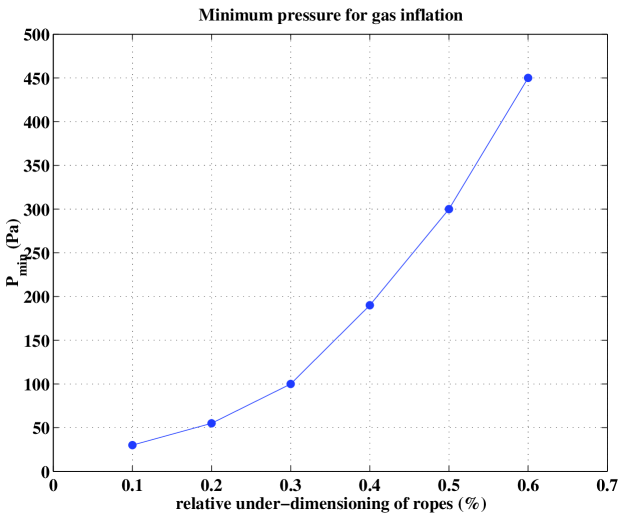
Bonds between adjacent nylon panels were made using a glue recipe from Nyltech of Acros Resorcinol and sodium meta bisulphite solution in water and ethanol. Glue is sprayed as a fine mist onto both surfaces of the joint. The glue chemically attacks a thin layer of nylon, making it tacky after a short exposure time. The two panels are clamped under pressure in order to produce a good seal and strengthen the bond. Various combinations of exposure time, glue amount, size of the droplets in the glue mist, applied pressure, and clamp time were tested. The optimal combination was found to be an exposure time of several tens of seconds, pressure in excess of Pa, and clamp time greater than 4 hours. Joints created with these parameters were mechanically stronger than the nylon film itself.
After continued exposure to light, the optical properties of these joints degraded slightly as the bond gained a greenish tint. However, no corresponding mechanical deterioration was observed.
Adjacent panels were sequentially bonded as described above and folded over to form an accordion-like stack (see Figure 4). Care was taken not to crease the nylon film at the folds. While the glue set, pressure was applied along the whole length of the seam with spring-loaded clamps mounted on the assembly tables. Remote-controlled carts were used to perform the cutting, glue-spraying, and folding steps (see Figure 5).
Once all panels of the IV were on the stack, the last seam was made by bonding together the edges of the first and last panels. The polar end regions were then put in place as described in section 4.3. The rope system was attached (section 4.4), followed by the optical fibers, temperature sensors, and load cells (section 4.5). The delicate operation of nesting the IV inside the OV was then performed. One meter of the final OV seam close to each pole was bonded first and the OV end regions were installed. After the IV was placed inside the OV (within one of the top folds of the OV stack to be precise), the rest of the OV seam was sealed. More details on the production operations are found in [13].
4.3 The polar region design and tube assemblies
The main challenge in building the polar end regions of the vessels consisted of making the transition between nylon film and bulk material with a low-mass, leak-tight, mechanically strong structure. The low mass is necessary to reduce the amount of radioactivity from material in the end regions. At each pole of the vessels is a set of tubes, the tube assemblies, connecting the vessels to the SSS, water tank, and fluid handling plants. These tubes carry the scintillator and buffer fluids into the IV and OV. They also transfer the buoyant load from the nylon vessels to the SSS. The transitions between the nylon vessels and the tube assemblies are by far the most delicate components of the system.
Three basic principles drove the design of the end regions:
-
•
The end regions need to be mechanically stronger than the nylon membranes to which they are connected. In the (unlikely) event of a catastrophic mechanical failure, we wanted to assure that the film envelopes would fail first for safety reasons, preserving the mechanical integrity of the supporting structure.
-
•
The end regions need to be leak tight; that is, the leak rate of the end regions must not contribute a significant fraction of the overall leak rate from the entire vessel.
-
•
The ray-induced background resulting from radioimpurities contained in the end regions should not contribute more than 0.1 events/day in the 250–800 keV energy range and for events localized in the innermost 100 tons fiducial mass. The corresponding requirements in terms of allowable radioimpurities in the material for the IV end regions are extremely stringent. Materials in the OV end regions have much less stringent requirements, due to their greater distances from the fiducial mass. Great effort has been put into minimizing the mass of the IV end region with the use of nylon film in place of bulk nylon and in carefully selecting the construction materials. Results are summarized in section 6.
The IV end region is shown in Figure 6. It consists of a nylon ring, a circular nylon film cap, the central nylon tube that carries IV fluid, and two flexible nylon tubes for direct fluid sampling and pressure measurement. Six diagonal copper struts between the ring and the central tube give mechanical strength against rotational and lateral stresses. Copper was chosen for struts in the IV for its low radioactivity content and greater strength than nylon. The OV caps have a solid nylon disk instead of the nylon bridge film and 8 stainless steel diagonal struts are used instead of copper ones. The more complex design of the IV end-cap minimizes its radioactivity at the smaller IV radius (the bridge film has significantly less mass than a bulk nylon plate and is intrinsically less radioactive) and prevents obstruction of light for events close to the IV poles. For the OV, stainless steel sampling tubes are used instead of the more delicate nylon ones.
The vessels and support structures are designed to withstand a load of 3000 N. This corresponds to a 5∘C temperature difference, or a 0.5% density difference, between the scintillator and the buffer region. The resulting localized stress on the nylon membrane is about 40 MPa (corresponding to a vertical force of 300 kg). This assumes that the ropes capture most of the 1400 kg buoyancy force and the film does not stretch. However, the film will stretch to relieve localized stress. A finite element analysis shows that after a short time the membrane stress will relax to 4 MPa. Some basic findings are presented in section 4.7 below.222A more detailed paper on the calculated stress levels of the nylon vessels is in preparation.
The assembly proceeded as follows: the IV nylon membrane, trimmed at the poles, is glued with Resorcinol onto a 60-cm diameter bulk nylon ring that acts as a collar on the inside of the vessel. (In order to maintain good levels of radiopurity, the bulk nylon pieces in the end regions were extruded, not cast.) An annulus of transparent nylon bridge film, 0.5 mm thick C38F nylon (the same type used in the prototype Counting Test Facility vessel), connects the collar ring to the nylon tube. Note that C38F has mechanical properties similar to those of Sniamid. It is first glued onto the central nylon tube assembly with the two flexible nylon sampling tubes and leak checked separately; it is then glued onto the collar ring. Finally, a second 60-cm diameter nylon ring is bolted onto the collar ring, clamping both the nylon vessel and the bridge film membranes between them. This second ring has a protruding lip, making it L-shaped in cross section (an “L-ring”), in order to provide anchoring points for the copper struts, and to fix the midpoint positions for the ropes that hold the vessels against buoyant and gravitational forces.
The gluing technique is shown in detail in Figure 7. A layer of C38F nylon film is glued onto the bulk nylon surface using pure formic acid. The bulk nylon surface is pre-treated with pure formic acid to improve the bond between film and bulk. Pressure is applied to form a seal. Thin nylon film is then Resorcinol-bonded onto the thick film as described in section 4.2. After the vessel membrane is glued onto the collar ring, the surface of the glue joint is cured with small amounts of raw formic acid to smooth the step at each joint. Such features, if not eliminated, would be natural channels for leaks.
The nylon tube and bridge film assembly were bonded similarly. The nylon tube section of the assembly had its surfaces treated with formic acid, then glued together with nylon and formic acid paste. The two 3/8-inch flexible nylon lines at each pole used for fluid sampling and pressure measurement were then added, attached by gluing in place with formic acid and a nylon Swagelok part. Each end tube was leak checked during assembly by pressurizing the system, mounted on a frame made for the purpose, with SF6 and sniffing for it from the outside. Mechanical and leak checking tests of prototype end region assemblies, as well as the final pieces, under the tensile design stress of 3000 N, exceeded the required specifications by many orders of magnitude.
The OV end regions are similar to the IV ones, but simpler. They do not incorporate a bridge film, since they obstruct much less scintillation light than the IV end regions would block if opaque. Instead, an L-ring is attached to a bulk nylon plate, which in turn connects to the stainless steel section of the central tube. The connection is made with an O-ringed flange and is performed during the vessel nesting step. No leak checking test was carried out for the actual OV end regions.
The two sets of tube assemblies are designed to transport fluids separately to each of the three volumes defined by the two vessels and the SSS, and in addition to keep the nylon vessels suspended in the center of the SSS, rigidly fixing their positions with respect to it. The tube assemblies must take the load of the vessels, while having stringent radiopurity requirements due to their proximity to the fiducial volume. In addition they accommodate fluid sampling lines and allow the passage of instrumentation lines for monitoring the vessels.
Connection of the tube assemblies to the SSS was implemented with double viton O-ring gaskets. A rotatable flange couples the south tube assembly and the south 1-meter flange of the SSS, in order to accommodate differing orientations of the north and the south 1-meter flanges.
| Component | 238U | 232Th | Knat | 60Co |
|---|---|---|---|---|
| [ppt] | [ppt] | [ppm] | [mBq/kg] | |
| Nylon rings (extruded) | 30 | 50 | 0.13 | 1 |
| Nylon tubes (cast) | 50 | 50 | 0.70 | 2 |
| Copper struts | 30 | 50 | 0.02 | 1 |
| Steel flanges | 150 | 920 | 0.15 | 15 |
| Steel tubes | 150 | 700 | 0.26 | 10 |
| Steel OV mount rings | 140 | 2100 | 0.13 | 20 |
| Steel OV flanges | 160 | 3300 | 0.07 | 2 |
Table 2 summarizes the radioactive contamination of materials in the end regions [27]. We found that extruded nylon has in general a lower K content than cast nylon, thus opted for extruded nylon in the components closest to the fiducial volume. An unexpected surprise was the level of the isotope 60Co in the steel parts. This anthropogenic isotope, which is often used for profile radiography in monitoring stainless steel production, decays by emission with the production of 1.17 and 1.33 MeV rays. Since the half-life of 60Co is 5.3 years, it is presumed that the levels actually present in Borexino once the detector is fully operational will be lower than those reported here.
Electropolished stainless steel is used for the outermost parts of the tube assemblies where they attach to the SSS; low activity nylon is employed between the two vessels. Due to the rigid radiopurity requirements, the steel portions of the tube assemblies have been welded with thorium-free rods. All the tube assemblies were pickled, passivated and precision cleaned before mounting.
4.4 The ropes
Each vessel is restrained by two sets of ropes to prevent vertical motion in each direction. Each set consists of 18 ropes for the IV and 20 ropes for the OV. The ropes wrap around the vessel longitudinally, with the rope ends attached to the stainless steel part of the tube assemblies. The center of each rope is routed through the L-ring opposite the rope ends. Nominal rope lengths are 27.526 m for the IV and 35.072 m for the OV. The ropes were pre-stretched, ensuring they were completely taut, before being cut to these lengths. For monitoring the tension in the ropes, load cells are employed where the ropes attach to the fluid tube. The tension in each IV rope would be 59 kg with a density difference of 0.5%.
In case the panels of the vessels were not aligned perfectly longitudinally, it was decided to allow the ropes to float freely over the vessel surfaces rather than being fixed to individual panels. This prevents the ropes from contributing a sideways component of force to the panels. In order to prevent several ropes from bunching up along one meridian of a vessel, all of them are attached to a perpendicular set of ropes. These horizontal ropes (seven on the IV and nine on the OV) are fixed to the vessels with tabs on the nylon panels. Thus the complete set of ropes forms a grid-like net over the vessels.
The choice of material for all of these ropes is critical due to stringent requirements for mechanical strength and low levels of radioactive contaminants. The rope used for Borexino is made of multistrands of Tensylon with an ultimate yield strength of 590 kg. Tensylon is an ultra-high molecular weight polyethylene manufactured by Synthetic Textiles. It has a tensile strength of 1.45 Pa, and a Young’s modulus of 9.6 Pa. The diameter of the ropes was chosen such that the maximum load would be 10% of the yield strength. Lifetime under this continuous stress is projected to be more than 10 years, but should be much longer under expected loads. Failure would eventually occur due to creep, an irreversible slow change in the arrangement of polymer chains under load. This creep has been measured for Tensylon to be unaffected by soaking in pseudocumene.
Potassium salts are typically used in the coating of nylon ropes, but must be avoided due to the presence of the naturally occurring radioactive isotope 40K. Tensylon rope (woven by Cortland Cable from fibers produced by Synthetic Textiles) is uncoated. Its total potassium content (all isotopes) was measured to be on the order of 0.2 ppm. Heavy metal contaminants in the Tensylon are also lower than or comparable to other ropes; see Table 3.
| Sample | 238U | 232Th | Knat |
| [ppt] | [ppt] | [ppm] | |
| Vectran, 1200 lbs. | 100 | 30 | 45.0 |
| Zylon 13 | 50 | 50 | 10.2 |
| Spectra, 300 lbs. | 60 | 500 | 7.5 |
| Aramid Technora T-000 | not measured | 5.7 | |
| Berkeley nylon monofilament | 90 | 150 | 0.2 |
| Tensylon by Cortland Cable | 70 | 160 | 0.5 |
| Tensylon (final batch) | 95 | 180 | 0.2 |
4.5 Instrumentation
A critical part of the vessel assemblies, although not directly related to containment of the scintillator, is the instrumentation. This encompasses a variety of sensors and calibration devices that measure temperature, rope strain, vessel position, and other local conditions.
4.5.1 Temperature sensors
The maximum temperature difference across the nylon vessels must be less than 5∘C. The density difference due to temperature swings can account for most of the buoyant force, as ton/m3/∘C for both the pseudocumene and PPO scintillator, and the pseudocumene and DMP buffers. In order to check for temperature gradients, a set of temperature monitoring sensors are installed.
On the vessels, four temperature sensors are mounted at each end, north and south. Two measurement points at each end are in the outer buffer volume: one set at the level of the SSS, and one halfway between the SSS and the OV. Two sensors are mounted at each end in the inner buffer volume, one at the level of the OV and a second 35 cm closer to the IV. These positions permit the measurement of vertical temperature gradients.
The temperature sensors chosen for the nylon vessels are custom made Pt100 RTDs produced by Fisher Rosemount, Italy. The sensors are Pt resistors, nominally 100 at a temperature of 20∘C. Their sensitivity is rated at C, better than the requirement of 0.2∘C. To read the sensors accurately, four copper wires are used to cancel the resistances of the cables themselves. These readout wires are embedded in MgO insulation; they are surrounded by a welded stainless steel conduit that carries them to the exterior of the detector. The mass per unit length of the conduit is 40 g/m.
4.5.2 Load cells
Load cells were installed to measure the buoyant force on the vessels due to differences in temperature and composition between the three fluid volumes. At a constant temperature, the buoyant upward force on the IV due to the difference in densities between scintillator and buffer fluids is 280 kg [13]. With a C temperature difference across the IV, the buoyant force on the IV goes from 1.58 tons in the upward direction to 1.02 tons in the downward direction. With the same temperature difference across the OV, there is a buoyant force of 2.45 tons. (The weight of the nylon vessels, strings and other mechanical parts is negligible.)
Buoyant forces on the vessels are transferred to the ropes and the tube assemblies. The force on both sets of components is measured using load cells. The selected load cell is the Sensotec model 34, which has a mass of 70 g. Each cell has a hysteresis no greater than 0.2% of the full-scale, and non-repeatability no greater than 0.05%. The temperature dependence of the cells is 0.005% of full scale per ∘C. Full scale (which may be tuned) is set at 500 kg force for the IV load cells, and 1000 kg force for the OV load cells.
The hold-down ropes are grouped together at their ends and attached to load cells. At the north and south pole of the IV, each of the 6 groups of 6 rope ends is connected to a load cell attached to the tube assemblies (for the OV, there are 8 groups of 5 rope ends at each pole). When the vessels are fully inflated, the load cells are attached to the central tube at angles of 58∘ and 53∘ from the vertical for the IV and OV, respectively. The maximum force expected on each load cell is thus 495 kg (510 kg) for the IV (OV).
The maximum force expected on the tube assemblies that support the vessels was calculated with a Finite Element Analysis simulation to be about 240 kg force. Load cells similar to those on the ropes, but with a lower capacity, are attached to the tube assemblies to measure this strain. There are two such load cells for each of the four tubes.
4.5.3 Calibration light sources and optical fibers
Since the two nylon vessels are not rigid, observing their precise shapes and positions may be important when defining fiducial volume cuts or making Monte Carlo simulations of external radiation. This monitoring ability is also one means by which the safety of the vessels can be ensured. In order to accomplish this, CCD cameras will be used to observe point-like light sources mounted on the outside surfaces of the vessels. The sources are 3/32-inch diameter teflon diffuser spheres attached to fiber optic cables, which are connected to a laser outside the detector. There are 38 light diffusers on the IV and 40 diffusers on the OV.
Eight additional optical fibers mounted on the IV are used for the purpose of monitoring scintillator quality. They use 355 nm light to excite the PPO in the scintillator near the membrane. A full description of the light diffusers and optical fibers, including their precise positions on the vessels’ surfaces, is provided in chapter 7 of reference [13].
4.5.4 Feed-through connections
To prevent leaks of the pseudocumene, the holding system is designed so that all fluids are doubly contained. Electrical cables from the instruments, optical fibers to the diffusers, and fluid sampling tubes from the vessels must therefore be routed through a complicated double set of feed-throughs.
The 44 electrical signals from temperature sensors and load cells run through wires completely contained in bellows. Wires run from these bellows through a conflat flange to meet a hermetically sealed feed-through isolated from the pseudocumene. There is also an individual feed-through for each of the 86 optical fibers.
To maintain a good seal where tubing from the vessels leaves the SSS, single tubes are welded directly to the flange coupling, which are joined with the feed-through fittings outside the SSS with Swagelok connectors. The connections of the tubes to the nylon vessels were sealed with metal gaskets. Seals between the tube assemblies and SSS were made with double viton o-ring gaskets for each tube.
4.5.5 Radioactivity measurements for instrumentation elements
It was necessary to ensure that radioactive background from the temperature sensors, load cells, and optical fibers placed inside the detector was sufficiently low. Radiopurity measurements of these components are detailed in Table 4. The primary contribution from the temperature sensors is due to the long stainless steel conduits that go out through the feed-throughs. Most of the lengths of these conduits are far from the IV; hence the relatively high levels of radioactive contaminants are not as damaging as one might think at first look. It should also be noted that the measured load cell was not equipped with a Swagelok connector. However, the stainless steel Swagelok is not expected to make a large contribution.
| Component | Mass | 238U | 232Th | Knat | 60Co |
| [g] | [ppt] | [ppt] | [ppm] | [mBq/kg] | |
| Light diffusers and optical fibers | |||||
| Teflon beads | 1 | 18 | 29 | 13 | - |
| Resorcinol | 1 | 26 | 100 | 0.051 | - |
| Formic acid | 1 | 2 | 2 | 0.014 | - |
| Optical fibers | 500 | 50 | 30 | 0.135 | - |
| Load cells | 1120 | 4500 | 2000 | 1 | 14 |
| Temperature sensors | 40 g/m | 33000 | 1900 | 3.4 | 9 |
4.6 Leak tightness specifications and leak checking
The assumption of a 10 year experimental lifetime with no fluid purification sets the leak tightness specification for the entire IV assembly. The tolerable leak rate was determined by the amount of PPO allowable in the buffer-quenched volume (inner buffer) between the two vessels. DMP leaking into the IV is much less worrisome. PPO concentrations in the inner buffer must be below 10 ppm; otherwise the overall trigger rate of the experiment would be too high [12]. The IV therefore has a leak tightness specification of cc/s of pseudocumene at a pressure difference of 1 mbar. This is equivalent to 1 cc/s of gas at the same relative pressure. (Strictly speaking, the equivalence is true only for viscous, i. e., not molecular, leaks, as the scaling from pseudocumene to gas is done using the ratio of viscosity coefficients.)
Since the leak rate in the OV is much less critical, the OV leak rate specification was conservatively set at cc/s/mbar of pseudocumene. Leak specifications for the individual end regions were set to no more than a fraction of the overall vessel specifications, specifically, 10-3 cc/s liquid leak rate for the IV end regions and 0.1 cc/s for the OV end regions at 1 mbar overpressure.
The tightness of the bonding technique was tested by bonding together two 3 m long panels to form an inflatable, cigar-shaped balloon. For testing, the prototypes were filled with air and a trace amount of SF6 gas. Leaks were measured with a residual gas analyzer sniffing near the joints. The tests were done at 50% relative humidity, and the film was creased and crinkled severely before inflation. No noticeable leak increase was observed within a sensitivity of cc/s of pseudocumene, scaled to the size and operational differential over-pressure of the Borexino IV of 1 mbar. To a good approximation, gas and liquid leak rates differ by the ratio of the viscosities. The liquid leak rates quoted above are thus approximately 100 times smaller than the explicitly measured gas leak rates.
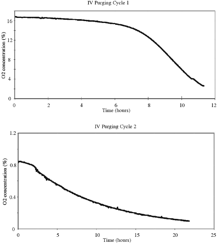
The entire IV assembly was also tested shortly after fabrication. Once the IV was completed with the addition of the endrings (section 4.3), a table top leak test was performed. The folded IV was first slightly inflated with humidified pure SF6 gas to an over-pressure of about 0.1 mbar. A thick layer of polyethylene film was placed around the vessel stack and tightly taped to the table, forming a closed volume in which a leak of SF6 would accumulate. The cover layer was then lifted and the concentration of SF6 in the sealed clean room measured as a function of time. Gas mixing in the clean room is essentially instantaneous (Figure 8, left), so the SF6 concentration step and the volume of the clean room give the amount of gas that has leaked. Consideration of the accumulation time and the over-pressure gives the leak rate. The measured leak rate was 10-3 cc/s/mbar of pseudocumene; this value was 10 times better than the design goal (Figure 8, right).
In addition, the vessels were also leak checked once they were installed at Gran Sasso; see section 5.3.2 for details.
4.7 Calculated stresses on the nylon film
In the Borexino design, the nylon vessels sit in a nearly buoyancy-free environment. The presence of different additives in the pseudocumene inside (1.5 g/liter PPO) and outside (5.0 g/liter DMP) the IV induces a density difference across the film, with scintillator 0.09% less dense than buffer fluid [13]; this gradient could be enhanced to a few tenths of a percent in the unlikely scenario of a uniform and relatively large temperature difference between the fluids inside and outside the vessel. The resulting buoyant force would pull the vessel up or down, depending on the direction of the density gradient, and reaction forces would develop at the contact with the hold-down ropes and the junction of the film to the end regions. As a result, in-plane stresses pull on the nylon membrane. The membrane responds elastically, up to a certain point, and then yields to creep until equilibrium is reached.
In order to evaluate the membrane stress and whether it is a challenge to the vessel structural integrity, we performed a static Finite Element Analysis (FEA) using version 6.1 of ABAQUS/Standard, a commercial Finite Element Algorithm for non-linear structural analyses. Under the approximations of neglecting friction and creep, the problem was also addressed analytically with the EMsolver code [40]. When the FEA model (which also does not take frictional forces directly into account) was tweaked to exclude the effects of creep, the results were in good agreement.
The structural analysis exploits the cyclic symmetry of the vessel around the axis and only models one nylon film panel, with glued seams at the edges and two ropes (section 4.4) running over its middle, one wrapped around the top and one around the bottom. The analysis is performed in a spherical coordinate system, with in-plane stresses considered along the meridional () and hoop () directions. Symmetry around the axis is enforced by the ABAQUS Multi Point Constraint, which equates radial, circumferential and axial displacement components of the nodes on the left and right edges of the film panel. In addition, all translational and rotational degrees of freedom of the end regions are constrained, while the boundary between end region and nylon membrane retains rotational degrees of freedom. The ropes are not allowed transverse motion.
The analysis models the end regions with 1 cm nylon shell elements, the ropes with beam elements of 1.75 mm radius and the mechanical properties of Tensylon, and the internal volume of scintillator as an incompressible fluid of 889 kg/m3 density inside the vessel. The nylon envelope is modeled with membrane elements, thin surfaces that offer in-plane strength but no bending stiffness. We used a realistic initial overpressure Pa. As the density gradient induces a buoyant load, which in the following we assume to be upwards, the incompressible fluid reacts by increasing its own internal pressure, from the initial value to a final value . The resulting pressure differential across the membrane is a positive number (points outwards), depending on the z coordinate, which for at the bottom, m at the top, is with .
For large membrane stress ( of the tensile yield), the elastic model and Hooke’s law lose accuracy. The nylon film response to external loads is viscoelastic, as the molecules realign themselves and the stress-strain relation changes in time, as described by the normalized creep compliance:
| (1) |
where is the time-dependent strain associated with a constant stress and is the Young’s modulus. In a linear viscoelastic material, the normalized creep compliance is not a function of the applied stress . We modeled the film creep with the ABAQUS quasi-static, viscoelastic analysis option. We treated nylon as a linear viscoelastic material, which is realistic up to about 30% of the tensile yield, with the creep compliance measured under uniaxial tension at 20% relative humidity.
It must be noted that wrinkling (caused by regions of compressive stress) and creep cannot be simultaneously treated by our model. A separate analysis that takes wrinkling but not creep into account, using the uniaxial tension mode, has also been performed, though there is insufficient space to discuss the results in detail. We found that in the worst-case scenario, the stress in the film rapidly causes creep; hence creep cannot be neglected and the analysis needs to be viscoelastic. If the vessel starts out slightly over-inflated (we assumed 50 Pa), wrinkling becomes a very small effect and the viscoelastic analysis without creep does a good job of simulating the vessel.
Figure 9 and Table 5 show how the stress profiles change depending upon whether or not creep is taken into account, in the two conditions of 20% and 100% relative humidity of the environment. Regions with negative stress are those where wrinkling, not properly modeled by the viscoelastic analysis, would occur.
The contact between nylon film and rope is the most challenging task in the model: the rope follows the deformation of the film, but at the same time constrains it and the way this interaction is modeled has important consequences on the analysis results. Static friction between film and rope attenuates the buoyancy-induced shape deformation and reduces the stress divergency at the bottom end-plate. We do not have a measurement of the static friction coefficient between film and rope in presence of water or pseudocumene333The Tensylon datasheet reports for the ropes; values for generic nylon in the literature are in the 0.4–0.7 range. The datasheet for Capran film (physically similar to Sniamid and Capron) has values between 0.5–0.75 in some cases, or up to 1 in others (film-to-film coefficient of friction)., so neglecting friction is the conservative thing to do. If we assume a static coefficient of friction of 0.5 in our worse-case scenario (0.5% density difference, wrinkling, no creep), the hoop stress in the upper hemisphere remains in the 9–10 MPa range, but the meridional stress divergence at the south pole drops from 27 MPa (no friction) to 9 MPa.
The rope length is also a factor in the final stress pattern. If the ropes are slack, the stress is larger, as the ropes allow for a larger vessel displacement than design, but the difference is only visible at the bottom end-plate: in the viscoelastic analysis, if the rope is 0.35% too long (9.5 cm), the equilibrium is reached at about 10 MPa instead of 6 MPa. If the rope is 0.35% shorter than design, the level is 5 MPa. From these results, it appears to be convenient to pre-stretch, or under-dimension the ropes by some small amount, compatible with minimizing wrinkles at the bottom end-plate during inflation. Figure 10 shows the minimum pressure required, at inflation, to avoid wrinkles if the rope is initially under-dimensioned by a certain percentage amount. Friction was not included in these calculations; this is purely a length conservation issue. The plot hints that we can afford a 0.2% undersize of the rope if, during filling, the vessel is maintained at a 50 Pa overpressure. (In fact, the vessel ropes were made slightly undersized, as can be seen by the visible scalloping of the film in Figure 13, and the overpressure is being maintained at this 50 Pa [5 mm H2O] value.)
The conclusion we can draw from the FEA model is that if we account for the creep of nylon under stress and if the hold-down ropes are not over-sized, even in the conservative assumption of no film-rope static friction, in the worst-case scenario the membrane stress on the vessel is at or below 10% of the nylon tensile yield. In practice, we expect about 5 times lower buoyancy, due only to the difference in density between scintillator and buffer fluids at the same temperature. (The OV, which separates two volumes of buffer fluid, would experience no buoyant stresses at all.) Thus we can consider the nylon vessels structurally safe for operation.
| R | P | Stress | ||||||
| min | max | mean | bottom | top | Meridional | Hoop | Rope | |
| (cm) | (cm) | (cm) | (Pa) | (Pa) | (MPa) | (MPa) | (MPa) | |
| 20% R.H. - Density gradient: 0.1% | ||||||||
| Elastic | -5 | 3.5 | 2.2 | 82 | 156 | 5.9 | 2.3 | 13 |
| Creep | -15 | 11 | 6.4 | 57 | 131 | 2.1 | 1.5 | 14 |
| 20% R.H. - Density gradient: 0.5% | ||||||||
| Elastic | 16.5 | 13 | 8 | 239 | 607 | 22.3 | 8.5 | 57 |
| Creep | 31 | 25 | 15 | 153 | 521 | 5.4 | 4.4 | 67 |
| 100% R.H. - Density gradient: 0.1% | ||||||||
| Elastic | 8 | 5 | 3.3 | 76 | 150 | 3.4 | 2.0 | 14 |
| Creep | 18 | 14 | 8 | 51 | 125 | 1.4 | 1.3 | 15 |
| 100% R.H. - Density gradient: 0.5% | ||||||||
| Elastic | 22 | 18 | 11 | 203 | 571 | 12 | 6.7 | 63 |
| Creep | 36 | 29 | 17 | 129 | 497 | 3.2 | 3.3 | 68 |
5 Shipping and installation in Gran Sasso
5.1 Packaging and shipping
To prepare for shipping the vessels, water was inserted at each of the two ends into the outer vessel (OV), to keep the vessels moist and the air humid. Then the nested vessels were triple-bagged: two layers of polyethylene film and a third aluminized film layer were wrapped around the vessels and heat-sealed. The aluminized film prevented diffusion of radon into the vessels.
After the sealing of the envelope, the vessels were folded into a packing frame of approximate dimensions 2.2 m 4 m. The frame held the two end regions vertically. The nylon envelope was folded in the central region of the frame, as shown in Figure 11. The frame was designed to fit in a wooden crate at a standard airline cargo size. The crate was instrumented with accelerometers and tilt meters to monitor the stress to which the vessels were subject during the shipping. The crate was flown from Newark, New Jersey, USA to Milano, Italy, then trucked into LNGS.
The feed-throughs (section 4.5.4) were added to the vessel end regions after they had been shipped to LNGS.
5.2 Installation of the nylon vessels
To install the nylon vessels, the north and south end regions needed to be attached at the top and bottom of the stainless steel sphere (SSS). Installation was a challenge because of the weight of the vessel assembly, the 13 m length of the film panels, and the large and delicate end regions. Furthermore, this work had to avoid damaging the phototubes inside the SSS, which were already installed everywhere except for a small region on the floor. The vessels had to be kept supple throughout the installation, so they were continuously sprayed with deionized water and the humidity in the SSS was kept %.
After their arrival at LNGS, the nylon vessels were unpacked in a clean room connected to the SSS entrance. Scaffolding was built in the clean room and SSS to keep the vessels off the floor and then lift them in a controlled manner. The vessels were first suspended horizontally from an I-beam track in the clean room. They were moved along the track up through the 3 m port into the SSS. Motion was controlled with a system of winches and pulleys. Once the north end region entered the SSS, it was rotated vertically and raised to the top, 14 m above. The nylon film was unfolded as it entered the SSS, following the north end region. While the north end region was raised, the three layers of bagging protecting the film were cut away.
Once the north end region was attached, the film could not simply be allowed to hang because it was too long. The length of the film panels when lying flat is a factor of longer than the final diameter of the spherical inflated vessels. Excess film was stored on a platform on top of the scaffolding in the SSS. When enough film had been gathered, the south end region was hoisted upward, rotated vertically, then lowered and attached to the bottom of the SSS.
A photograph of the nylon vessels partway through the installation is shown in Figure 12.
5.3 Inflation with synthetic air
Like the initial installation, inflation of the vessels is complicated by the fact that, in their folded state, the vessels were a bit under /2 times longer than the diameter of the SSS. The excess film was held, still folded, in the carriage used for installation. During inflation, gas was introduced from the top, so that an expanding inflated region of the vessels pulled film from the carriage. Unfolding of the film was controlled by hand from the installation scaffolding, which was disassembled as the inflation proceeded. At all times, the vessels were kept in a humidified, non-brittle state (as described above) by maintaining 80% relative humidity. Figure 13 shows the fully-inflated nylon vessels.
5.3.1 Radon limits on synthetic air
The vessels were inflated using humidified ultra-low radon air (synthetic air was used rather than pure nitrogen, in order to protect workers inside the nearly-sealed SSS from suffocation in the event of a vessel rupture.) The synthetic air was produced by mixing high purity boil-off nitrogen from the Borexino nitrogen plant [41] with oxygen that had been aged in clean stainless steel bottles to let its radon decay.
The lines used to carry the synthetic air, part of the Borexino permanent plants, were all made out of electroplated stainless steel. They were extensively purged with clean nitrogen, and the particulate level at the delivery point was measured to be better than class 1. The radon activity of synthetic air injected inside the vessels was continuously monitored, after it had gone through the inline humidifier, by diverting a small amount from the main flow and bleeding it through a large electrostatic radon detector [42]. Radon levels were constantly below the 1 mBq/m3 sensitivity limit of the device.
For Rn, the main danger is that its daughters wash or leach from the vessels into the scintillator. Assuming a worst-case scenario of all daughters transported into the liquid, a Rn concentration of 0.1 mBq/m3 during inflation will lead to 1 count/day of all 210-chain daughters in the fiducial volume.
5.3.2 Leak rate tests
Both vessels were leak checked after inflation. SF6 tracer gas, aged to let radon decay away, was injected into the inner vessel (IV) air stream at 1% concentration. The leak checking strategy relied on measuring the SF6 concentration in the outer buffer volume (between IV and OV) as a function of time; with the IV over-pressure and the volume of the outer buffer it would yield the total IV leak rate. This technique turned out to be affected by sampling problems and by the difficulty of mixing the gas in the outer buffer. It gave an upper limit of 5 cc (gas)/s/mbar, equivalent to a liquid leak rate of 0.05 cc (pseudocumene)/s/mbar.
A more sensitive method, applicable to both vessels, was to simply monitor the over-pressure trends of the IV and OV. After correcting for external atmospheric pressure fluctuations (the SSS was still open to the outside at this stage) and with a couple of months of data the following gas leak rates were recorded:
-
•
0.5 cc (gas)/s/mbar, or 0.005 cc (pseudocumene)/s/mbar, for the IV
-
•
10 cc (gas)/s/mbar, or 0.1 cc (pseudocumene)/s/mbar, for the OV.
The value for the IV is a factor of two better than the design specifications specified in section 4.6, and has to be taken as a conservative number in that the elastic deformations and creep of the membrane were not taken into account. The leak rate of the OV is at least one order of magnitude better than required.
5.4 Pressure control and DCS in filling stations
Because the vessels are among the most fragile parts of the Borexino experiment, it is necessary to monitor their volumes, pressures, and shapes continuously. If one or more of these parameters departs from the desired limits, it is necessary to take action to bring it back into the acceptable range. Borexino has a unique digital control system (DCS) to monitor and control all the process plants. In addition to showing the readouts of the strain gauges and temperature sensors on the vessels (refer to sections 4.5.2 and 4.5.1, respectively), the DCS was also used in the initial gas inflation of the vessels, and to ensure that the vessel parameters remained in a steady state while waiting to begin the process of filling the detector with water.
Since the atmospheric pressure in the laboratory may vary freely, the crucial parameters for these operations are the differential pressures across the IV and across the OV. These values are measured using differential pressure (dP) cells connected to the DCS. The dP cells are the Fisher Rosemount model 3051C. They are highly accurate, to 0.04% of their full range.
During the initial inflation, automatic interlocks between the dP cells and the valves used for gas insertion were used: in case a value went higher then the set threshold, if the interlock was enabled, the connected valves would close, stopping the inflation. The total value of the strain gauges gave a good indication of the inflation state. (The strain gauges and the temperature sensors will also be critical in monitoring the vessels during the filling with water and pseudocumene.) Other useful parameters monitored during the inflation included the relative humidity (this was kept high in order to keep the nylon film supple) and the oxygen content of the synthetic air.
For many months, the vessels remained inflated with synthetic air. During these static conditions, as well as during the following purges with nitrogen, critical high-level alarms are set on the dP cells via the DCS. On the basis of their readouts, actions to re-inflate or deflate one or both vessels may be taken.
In addition to the DCS, the vessels have a passive system for control of differential pressures, consisting of two bubblers. By changing the levels of the water in these, it is possible to set the maximum differential pressure allowed between the three volumes. The idea is to use this passive system as a last resort to save the vessels in case of sudden drastic changes.
5.5 Purging with nitrogen
Normal air, even when dust-free, has an activity of several Bq/m3 due to the presence of radon and other radioactive noble gas isotopes. Even one cubic centimeter of air thus implies about one radioactive decay in the fiducial volume per day. It is therefore crucial to purge the inflated vessels with ultra-pure nitrogen before filling them with water or scintillator.
The purging gas used in the vessels has very stringent radiopurity requirements. The primary concerns are 222Rn and the beta emitters 39Ar (565 keV endpoint, 369 yr half life), present in natural Ar at a level giving 1.2 Bq/(stp m3 Ar), and 85Kr (687 keV endpoint, 10.8 yr half-life), present in natural Kr at a level giving 1 MBq/(stp m3 Kr). Kr and Ar will diffusively or convectively be transported into the water during water filling, and then to the pseudocumene during water displacement by pseudocumene. Rn introduced with the gas will quickly decay, leading to 210Pb, Bi and Po deposited on the surfaces of the vessels.
The amount of Kr and Ar transfered to the scintillator from the purge gas depends on the relative solubilities of these gasses in N2, water and pseudocumene, and the amount of mixing or diffusion. Conservatively we assume full equilibration between Kr and Ar in the gas/water phases during water filling and subsequent full equilibration of Kr and Ar between pseudocumene and water during pseudocumene displacement of the water. The relevant solubilities are shown in Table 6. With a goal of 1 count/day in the fiducial volume, we arrive at required (volume, or molar) concentration limits of 0.37 ppm for Ar, and ppt Kr in the purge gas.
| Gas | water | pseudocumene (est.) |
|---|---|---|
| Ar | 0.039 | 0.23 |
| Kr | 0.073 | 0.77 |
| Rn | 0.295 | 12.96 |
To start with, the SSS was filled with normal air, while the nylon vessels (IV interior and inner buffer region) had been inflated with synthetic air. During this time period, Kr and Ar had diffused into the nylon film and tubes of the vessels; the volume of these gases trapped in these plastic parts was equivalent to a few liters of air. Purging therefore was done in stages, with a few weeks between each stage, to allow the Kr and Ar to diffuse back out. The first several stages, amounting to five volume exchanges within the IV, were done with high purity nitrogen (HPN) with a concentration of a few ppm Ar. The purging was finished with 14 volume exchanges in the IV of special low Ar and Kr nitrogen (LAKN).
During purging, the relative humidity of the nitrogen was maintained at over 60% to preserve the flexibility of the nylon vessels. Flow rate of the incoming gas was about 25 m3/hr for the inner buffer, and 30 m3/hr for the other two volumes. Differential pressure between the vessels was kept below 5 mm H2O at all times.
Concentrations of the relevant gases, O2, Ar, SF6 (used as a tracer), and N2, in gas leaving the vessels at the bottom were monitored at 5 s intervals with a residual gas analyzer. At the end of each purging stage, more accurate measurements, scanning all mass numbers, were taken. During the first stage (top of Figure 14), the reduction factor in the IV was about 20, much higher than the expected per-volume factor of e (2.718). This is a result of stratification in the vessel, with the pure lighter N2 coming in from the top and denser air exiting at the bottom. In following stages, the reduction factor per volume was much closer to e with complete mixing, shown in the bottom of Figure 14 (the second purging stage was about 2 volumes).
6 Summary of Radiopurity
In a low background experiment such as Borexino, each detector component is subject to strict radiopurity requirements. The nylon film for the inner vessel (IV), in particular, is a potential background source from emission (external background) and from Rn emanation into the sensitive volume (internal background). Other structural components of the detector also release rays and Rn, although most of the externally produced Rn will be barred from entering the volume of scintillator by the two nylon vessels.
6.1 Gamma backgrounds
The design requirement for the radiopurity of materials used in the vessel fabrication is that the nylon vessels and their associated parts should produce a background rate less than the background from the photomultiplier tubes and light cones mounted on the stainless steel sphere (SSS). (Though the selected phototubes incorporate special low-radioactivity Schott 8246 glass, the glass nevertheless has concentrations of 30 ppb U, 10 ppb Th, and 20 ppm K by mass, resulting in the phototubes being among the main sources of external rays.) Moreover, the overall background in the neutrino window should be less than the neutrino rate.
The radius of the IV is 4.25 m, while the radius of the fiducial volume is 3 m. Thus, there is an active shield of 1.25 m between the vessel and the part of the detector from which neutrino event data will be used. With this shield, the maximum allowed concentrations of U, Th and K in the nylon film are 10 ppt, 20 ppt and 30 ppb, respectively. Such limits guarantee that the external background from the IV film is less than 10% of the external background from the photomultiplier tubes. The thin, flexible IV membrane has a total mass of only 32 kg. We note that the use of a rigid shell instead, which by necessity would be much more massive, as a scintillator containment vessel in Borexino would have required much more stringent limits on the permissible concentrations of emitters.
The materials used in the construction of the outer vessel (OV) end regions (see Table 2) are the principal sources of vessel-related background. Table 7 reports the simulated background from each end region component in the energy windows for 7Be neutrinos (250–800 keV) and neutrinos (800–1300 keV) in different fiducial volumes. The steel flanges and the steel pipe located half-way between IV and OV contribute the most, due to the 60Co content in steel. As noted above, these numbers are conservative because the 60Co half-life is only 5.3 years.
For ease of comparison, Table 7 shows the predicted neutrino rate and the expected background from the end region components, nylon membranes, phototubes, their light cones, and the SSS. The table was constructed using the GENEB (GEneration of NEutrino and Background interactions) Monte Carlo software developed expressly for simulation of the Borexino detector [45], including a simulation of the finite resolution of position reconstruction. The radial dependence of neutrino and external background events in the 0.25–0.8 MeV energy window can be seen in Figure 15: the different behaviors make the fiducial volume cut a powerful tool to suppress this type of background.
| Component | Position | Mass | All | 200 t | 100 t | |||
| [m] | [kg] | NW | pep | NW | pep | NW | pep | |
| nylon rings | 4.25 | 5.2 | 124 | 107 | 2.16 | 1.53 | 0.15 | 0.180 |
| nylon hubs | 4.25 | 0.4 | 12 | 8 | 0.43 | 0.14 | 0.03 | 0.008 |
| Cu rim brackets | 4.35 | 1.6 | 32 | 17 | 0.53 | 0.25 | 0.03 | 0.025 |
| nylon tubes | 4.25–4.9 | 1.9 | 31 | 27 | 0.73 | 0.45 | 0.14 | 0.060 |
| Cu struts | 4.25–4.9 | 11.2 | 56 | 21 | 1.21 | 0.40 | 0.23 | 0.034 |
| nylon flanges | 4.9 | 0.6 | 1 | 1 | 0.04 | 0.04 | 0.01 | 0.009 |
| steel flanges | 4.9 | 3.4 | 63 | 29 | 1.47 | 1.53 | 0.30 | 0.061 |
| steel tubes | 4.9–5.6 | 6.9 | 66 | 30 | 2.52 | 1.70 | 0.68 | 0.176 |
| IV rope attachment | 5.45 | 3.7 | 4 | 1 | 0.14 | 0.09 | 0.02 | 0.002 |
| steel OV mount rings | 5.5 | 7.8 | 13 | 6 | 0.32 | 0.31 | 0.06 | 0.011 |
| steel OV tubes | 5.5 | 2.6 | 2 | 1 | 0.06 | 0.06 | 0.01 | 0.003 |
| steel OV flanges | 5.6 | 11.3 | 6 | 2 | 0.23 | 0.16 | 0.03 | 0.004 |
| 4 pipe load cells | 5.2 | 0.3 | 3 | 2 | 0.09 | 0.09 | 0.02 | 0.003 |
| 12 string load cells | 5.4 | 0.8 | 2 | 1 | 0.06 | 0.06 | 0.01 | 0.002 |
| temperature sensors | 4.9–5.6 | 0.2 | 9 | 4 | 0.39 | 0.09 | 0.04 | 0.003 |
| Subtotal, End Regions | 424 | 257 | 10.38 | 6.90 | 1.76 | 0.581 | ||
| IV nylon film | 4.25 | 32.1 | 52 | 60 | 0.39 | 0.34 | 0.01 | 0.006 |
| optical fibers | 4.25 | 0.5 | 15 | 9 | 0.12 | 0.07 | 0.01 | 0.001 |
| ropes | 4.25 | 4.5 | 332 | 180 | 2.45 | 1.58 | 0.06 | 0.028 |
| Subtotal, Nylon Vessels | 823 | 506 | 13.34 | 8.89 | 1.84 | 0.616 | ||
| light cones | 6.3–6.5 | 896 | 494 | 18 | 18 | 0.6 | 0.4 | |
| phototubes | 6.5–6.85 | 1280 | 651 | 25 | 26 | 0.6 | 0.4 | |
| SSS | 6.85 | 496 | 207 | 10 | 9 | 0.2 | 0.2 | |
| Total, Borexino | 3495 | 1858 | 66 | 62 | 3.2 | 1.6 | ||
| Neutrino rate | 4.25 | 89 | 4 | 64 | 2.8 | 32 | 1.4 | |
6.2 Radon diffusion through nylon
A more stringent radiopurity requirement is the amount of radon allowed to diffuse into the scintillator before it decays into 218Po and succeeding, essentially non-diffusing, daughters. The diffusion of radon through nylon films, if known, may be used to evaluate the potential background from radon originating in the bulk nylon due to 226Ra impurity in the material, and due to radon that originates in the buffer region and diffuses through the membrane into the scintillator.
The passage of radon through nylon, regardless of whether a Rn atom originates within the IV nylon film and travels into the scintillator, or instead travels from the outside to the inside of the IV, is governed by the diffusion equation, with two additional terms accounting for the radon decay and for any radon produced within the nylon:
| (2) |
Here, is the local radon concentration at a point within the film, is the diffusion coefficient of radon in nylon, the radon mean lifetime of 5.5 days, and the production rate of radon (or equivalently, decay rate of radium) per unit volume of nylon.
The problem is essentially one-dimensional when, as in Borexino, the vessel radius is much greater than the membrane thickness . We may presume a steady-state solution. An important length scale, giving the mean distance that a radon atom travels (projected onto the radial direction) through the nylon film before it decays, is
| (3) |
6.2.1 Permeability of nylon to radon
The permeability of non-decaying atoms through a membrane is defined as the product of the solubility (the ratio of concentrations of a solute at the interface between two solvent materials) with the diffusion coefficient, which regulates the speed of propagation through the membrane material. In order to take into account the decay of 222Rn as it crosses the nylon membrane, we define an effective permeability, which depends on the membrane thickness and on the diffusion length , which was defined in eq. 3:
| (4) |
In this particular case, the solubility factor is defined as the ratio of the radon concentration in the fluid touching the nylon to the radon concentration in the nylon itself at the surface.
| interface | RH | d | ||||
|---|---|---|---|---|---|---|
| [m] | [cm2/s] | [m] | [cm2/s] | |||
| PC/PC | 15 | – | – | – | ||
| H2O/PC | 100 | 135 | 120 | |||
| N2/N2 | 18 | 10 | ||||
| N2/N2 | 18 | 10 | ||||
| N2/N2 | 18 | 14 | ||||
| N2/N2 | 18 | 30 | ||||
| N2/N2 | 18 | 79 | ||||
| N2/N2 | 18 | 248 |
The diffusion constant in nylon depends strongly on the relative humidity of the nylon, and increases as the humidity is raised. It is such that the diffusion length is m for dry nylon and m for wet nylon. The effective permeability increases likewise. Table 8 reports measured diffusion coefficient, solubility and the effective permeability of 222Rn in a m nylon barrier at various relative humidities.
The first two rows in the table report results obtained in Princeton and described in reference [19]. These measurements were conducted with fluid on both sides of a nylon membrane, in order to reproduce the experimental conditions for the IV. On one side of the membrane was a small can with radon-saturated fluid (either pseudocumene or water), on the other side a larger cylindrical stainless steel tube held radon-free scintillator (pseudocumene plus fluors), viewed by two phototubes that measured the decay rate of radon permeating through the membrane, function of time. In the first case, with dry pseudocumene on both sides, the diffusion was below the sensitivity limit for the apparatus, even using the thinnest available nylon film (m nylon-6). The second (wet) measurement was performed with C38F nylon film of thickness comparable to that of the Borexino IV.
The remaining entries in Table 8 are for measurements performed by our collaborators in Heidelberg and Kraków [35], in which a m nylon C38F membrane was held in a nitrogen atmosphere at a known relative humidity: on one side the gas contains a known amount of radon, from a source, and on the other side a photomultiplier tube is used to detect radon that has permeated through the membrane. In order to control the humidity, the nitrogen is passed through a two-liter glass flask partially filled with acqueous solutions of various salts; depending on the salt, it was possible to obtain several standard humidity values in the gas phase in equilibrium above the solution.
6.2.2 Radon emanation from nylon
In general, the concentration of radon within the nylon film will be much greater than that in the liquid in contact with either inner or outer surface, as pseudocumene may be purified much more efficiently than nylon. Therefore, in the limit of a large mean travel distance for a radon atom, , the average radon activity within the Borexino scintillator would be one-half of the total activity within the IV film, scaled by the ratio of the nylon volume to the scintillator volume. (The other half would diffuse outward into the inner buffer volume.) In particular, this upper limit corresponds to about 10 radon events per day within a 100-ton fiducial volume, if we assume complete mixing of the scintillator. Convection in Borexino is actually unlikely, due to a fair temperature gradient (a few-degree increase from bottom to top), so the actual radon activity within the fiducial volume should be much smaller.
More detailed calculations [30, 35] indicate that radon activity within the 100-ton fiducial volume, due to radon emanation from the IV, will be between 1–7 radon decays per day, depending upon the actual relative humidity seen by the nylon film. Again, these figures presume complete mixing of the scintillator on a time-scale comparable to the radon mean lifetime or less.
In the assumption of secular equilibrium, the 222Rn emanation from ppt 238U in nylon and emanating into the fiducial volume, in a dry Borexino detector, is equivalent to the 222Rn from less than 10-17 g of 238U per gram of scintillator. We are hence fairly confident that radon emanation from nylon will be a small effect compared to uranium (and radium) contamination in the scintillator fluid.
6.2.3 Principle of the outer vessel barrier
The OV was designed to be a radon barrier that would minimize the radon concentration near the IV. The plan for the OV barrier was based on the concern that the outer region of the SSS, which includes the phototubes and SSS inner surface, could contain a significant quantity of dust due to the exposure of several months required for installation of the photomultiplier tubes. This is true even though the space was operated with filtered Class 1000 clean-room air. Moreover, although this region was cleaned just before the closing of the SSS, a precision cleaning could not be accomplished due to the limited accessibility. A protective barrier was judged to be the best way to assure a low background from dust and radon at the IV.
The effectiveness of the OV as a radon barrier was evaluated by calculating the rate of radon diffusion through the nylon membrane [19]. The relevant parameters are the mean diffusion length (eq. 3), which is the mean distance a radon atom travels during its mean life days, and the thickness . The solution of the diffusion equation for a decaying substance through a barrier, with the simplifying hypothesis of relatively large concentration of radon () on one side and negligible concentration () on the other, yields the following:
| (5) |
where is the volume of the membrane, in the Borexino spherical geometry, and is the enclosed volume. If we substitute the definition of from eq. 4 and use the definition of diffusion length from eq. 3, the equation becomes
| (6) |
For wet film, the mean diffusion distance is m, which is comparable to the thickness of the film (m); then and . In this case, the result is consistent with the following intuitive explanation. If the membrane thickness is equal to the mean diffusion distance, then the flux of atoms going into the vessel is the number of atoms in the membrane divided by the mean life of radon. Since these atoms decay with the same mean life inside the vessel, the result is that the radon concentration (atoms/m3) within the vessel is the number of radon atoms in the barrier divided by the volume of the vessel. This ratio is the concentration in the membrane times the ratio of the volume of the membrane () divided by the volume of the vessel (). The concentration within the film is equal to the concentration outside the vessel times the solubility ratio for radon in pseudocumene and in nylon. The final result is that the concentration inside the vessel is given by
Consider only the OV for now. For m, m (the OV radius), it follows that, for dry nylon, eq. 6 yields
In the worst-case scenario of nylon in contact with water, , and
Thus, we find that a thin nylon film will serve as an excellent barrier even in presence of water.
In Borexino, with two concentric nylon membranes, the reduction factor for radon concentration between the outer buffer and scintillator volumes is roughly the square of the reduction factor for a single vessel. Incorporating geometric considerations (the intermediate inner buffer region is a shell, not a full sphere), we find this range for the ratio between radon concentrations in the scintillator (IV) and outer buffer (OB):
(the number on the left being the dry nylon value and that on the right, for complete immersion in water). Hence, by far the dominant contribution to radon within the scintillator will be emanation from the IV nylon itself.
As above, all of these formulas presume complete convective mixing of radon within the scintillator fluid. A lack of convection will imply that most radon atoms that manage to emanate from or pass through the IV film nevertheless do not ever reach the central fiducial volume of scintillator.
7 Conclusions
The Borexino nylon vessels have been installed within the detector for over three years. During this time, members of the Borexino collaboration have learned a great deal about how to ensure their safety under various operating conditions. Water filling of the detector was initiated in August 2006, and finished 3.5 months later. Already the detector has observed Čerenkov light from muons passing sideways through the detector, generated by the interaction of neutrinos (created at the CNGS facility of CERN [46]) with the water molecules.
Filling the detector with purified buffer and scintillator is ongoing in early 2007, to be followed shortly by filling the outer steel tank (muon detector and neutron shield) with water. When this final stage is finished, the detector will be complete, able to observe the 7Be and possibly and even CNO-cycle neutrinos. Only at this point will we know the levels of radioactive contamination present within the detector fiducial volume. We may say, optimistically, that there is no reason to believe any unexpected major radiocontamination issues will present themselves, and every reason to expect that the Borexino nylon vessels will fulfill all the needed requirements for operating successfully.
Acknowledgments
The authors would like to thank the following individuals and companies, all of whom have been critical in the design, construction, or installation of the Borexino vessels and development of associated technologies.
John-Paul Chou, Farng-Yi Foo, Charles Sule, Joseph Stritar, and Thomas Zhang were invaluable in the measurements of mechanical properties of nylon film at Princeton. The Borexino vessel construction crew included Julie Bert, John-Paul Chou, Joel Greenberg, Eric Hopkins, Brian Kennedy, Ted Lewis, John Saunders, Domenic Schimizzi, and Charles Sule. Davide Gaiotto was an important contributor to the research and development effort on the optical fibers. The vessel installation crew included Augusto Brigatti, Angelo Corsi, Antonio di Ludovico, Giuseppe di Pietro, Massimo Orsini, Sergio Parmeggiano, and others.
Evan Variano helped early in the research effort on radon diffusion. Other individuals involved in designing, building and operating the radon scrubber for the vessel construction clean room included Nick Darnton and Costin Bontas. Aldo Ianni, Matthias Laubenstein, and the late Burkhard Freudiger helped to monitor radon levels in the synthetic air during the vessel inflation. Radon and radium measurements performed by our collaborators at Heidelberg and Kraków, including Christian Buck, Gerd Heusser, Wolfgang Rau, Hardy Simgen, Wojciech Wlazło, Marcin Wójcik, and Grzegorz Zuzel, were invaluable.
Mathematical calculations of stress on the Borexino vessels came in great part from the work of Frank Baginski, Chris Jenkins and Bob Walls. Prototype vessels were inflated at the Princeton Plasma Physics Laboratory [20], and later at the Princeton University Department of Athletics’ Jadwin Gym, with the kind permission of both organizations. The Honeywell (Pottsville, PA) and mf-folien (Germany) extrusion plants permitted our inspections and implemented our suggested cleanliness precautions with more willing cooperation on their parts than we had any right to expect. We could not have selected and purified our materials without the work of Tama Chemicals, CleanFilm, and many other companies and institutions.
Funding for this paper and for the activities reported herein were provided by the National Science Foundation (grants PHY-0077423, PHY-0201141, PHY-0503816), and by the Instituto Nazionale di Fisica Nucleare. Co-author L. Cadonati gratefully acknowledges the support of NSF grant PHY-0107417. Co-author R. B. Vogelaar gratefully acknowledges the support of NSF grants PHY-9972127 and PHY-0501118.
References
- [1] The Borexino Collaboration, G. Alimonti et al., Astrop. Phys., 16 (2002) 205.
- [2] J. Bahcall et al., Astrophys. J. Let., 621 (2005) 85L.
- [3] L. Wolfenstein, Phys. Rev. D, 17 (1978) 2369.
- [4] A. Strumia, F. Vissani, Nucl. Phys. B, 726 (2005) 294.
- [5] The Borexino Collaboration, H. Back et al., Phys. Rev. C, 74 (2006) 045805.
- [6] F. Elisei et al., Nucl. Instr. Meth. A, 400 (1997) 53.
- [7] O. Ju. Smirnov et al., Instr. and Exp. Tech., 47 (2004) 69.
- [8] J. X. Prochaska, “The Design and Fabrication of Optimal Light Collectors for the CTF Upgrade”, Senior Thesis, Princeton University, Apr. 1993.
- [9] L. Oberauer et al., Nucl. Instr. Meth. A, 530 (2004) 453.
- [10] C. Galbiati and K. McCarty, Nucl. Instr. Meth. A, 568 (2006) 700.
- [11] O. Ju. Smirnov, Instr. and Exp. Tech., 46 (2003) 327.
- [12] M. Chen et al., Nucl. Instr. Meth. A, 420 (1999) 189.
- [13] A. Pocar, Low Background Techniques and Experimental Challenges for Borexino and its Nylon Vessels, Ph.D. Thesis, Princeton University, Nov. 2003.
- [14] J. Boger et al., Nucl. Instr. Meth. A, 449 (2000) 172.
- [15] M. Apollonio et al., Phys. Lett. B, 420 (2000) 397.
- [16] F. Boehm et al., Phys. Rev. D, 64 (2001) 112001.
- [17] The Borexino Collaboration, C. Arpesella et al., Proposal of Borexino: a Real Time Detector for Low Energy Solar Neutrinos, University of Milano and Istituto Nazionale di Fisica Nucleare, 1991.
- [18] G. Alimonti et al., Nucl. Instr. Meth. A, 406 (1998) 411; G. Alimonti et al., Astropart. Phys., 8 (1998) 141.
- [19] L. Cadonati, The Borexino Solar Neutrino Experiment and its Scintillator Containment Vessel, Ph.D. Thesis, Princeton University, Jan. 2001.
- [20] PPPL [DOE Princeton Plasma Physics Laboratory] News, 3:3 (2000), 11.
- [21] KamLAND collaboration, K. Eguchi et al., Phys. Rev. Lett., 90 (2003) 021802.
- [22] M. I. Kohan, ed., Nylon Plastics Handbook, Hanser Publisher, 1995.
- [23] http://www.honeywell.com/
- [24] http://www.basf.com/
- [25] http://www.rhodia-ep.com/
- [26] http://www.tama-chem.co.jp/english/
- [27] The Borexino Collaboration, C. Arpesella et al., Astrop. Physics, 18 (2002) 1.
- [28] http://www.mf-folien.de/
- [29] Department of Defense, “Military Standard 1246C. Product Cleanliness Levels and Contamination Control Program”, 1994.
- [30] K. McCarty, The Borexino Nylon Film and the Third Counting Test Facility, Ph.D. Thesis, Princeton University, June 2006.
- [31] J. R. Martin and R. J. Gardner, Polym. Engin. and Sci., 21 (1981) 557.
- [32] C. Galbiati et al., “Glass transition, moisture content and mechanical characteristics of Nylon”, Princeton University, Mar. 2001, unpublished.
- [33] F. Rodriguez, Principles of Polymer Systems, Francis & Taylor, 1996.
- [34] M. Wójcik et al., Nucl. Instr. Meth. A, 498 (2003) 240.
- [35] M. Wójcik, G. Zuzel, Nucl. Instr. Meth. A, 524 (2004) 355.
- [36] A. Pocar, AIP Conf. Proc., 785 (2005) 153.
- [37] B. Cabrera, private communication, Jan. 2007.
- [38] M. Leung, AIP Conf. Proc., 785 (2005) 184.
- [39] A. Hallin, private communication, Jan. 2007.
- [40] F. Baginski and W. Collier, AIAA J., 39 No. 9 (2001) 1662; F. Baginski and K. Brakke, AIAA J., 36 No. 10 (1998), 1901.
- [41] G. Heusser et al., Appl. Rad. and Isotopes, 52 (2000) 691.
- [42] J. Kiko, Nucl. Instr. Meth. A, 460 (2001) 272.
- [43] H. L. Clever, ed., Solubility Data Series Volume 4: Argon—Gas Solubilities, Pergamon Press, New York, 1980.
- [44] H. L. Clever, ed., Solubility Data Series Volume 2: Krypton, Xenon and Radon—Gas Solubilities, Pergamon Press, New York, 1979.
- [45] S. Bonetti et al., Nucl. Instr. Meth. A, 329 (1993) 314; B. Caccianiga et al., “GENEB: GEneration of NEutrino and Background”, INFN—Milano, Oct. 1997, unpublished.
- [46] R. Bailey et al., The CERN Neutrino beam to Gran Sasso (NGS): Addendum to report CERN 98-02, INFN/AE-98/05, CERN-SL/99-034(DI), INFN/AE-99/05, unpublished.
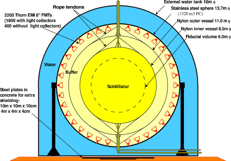
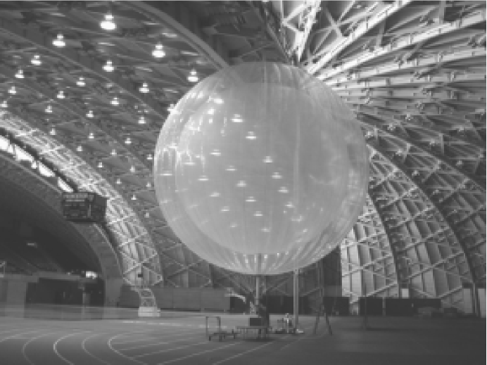
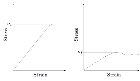

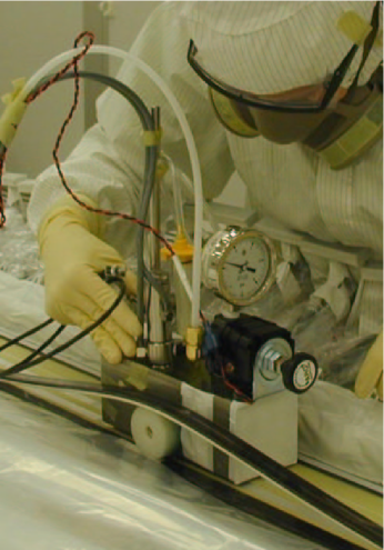
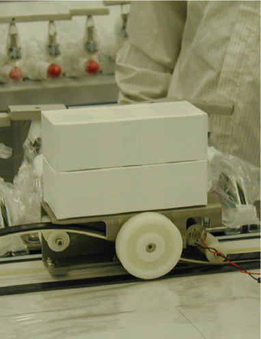
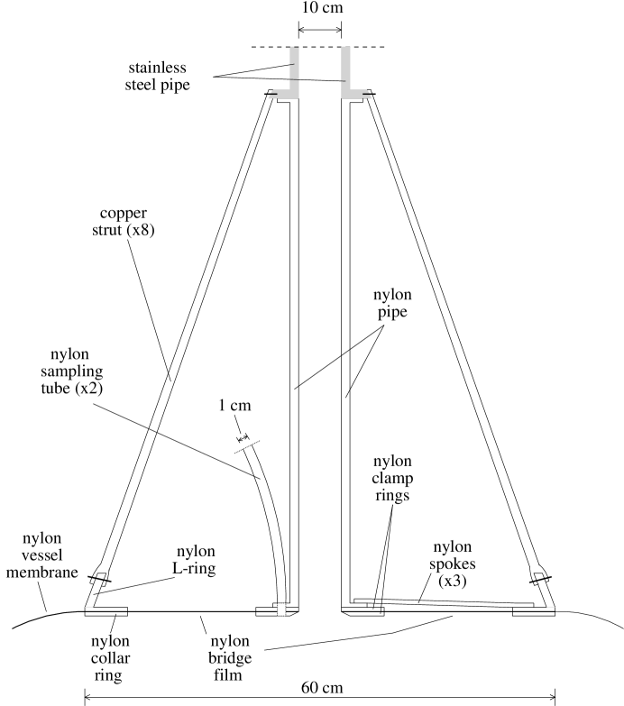
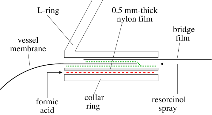
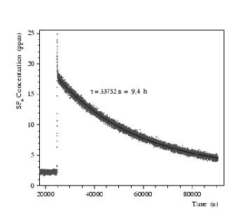
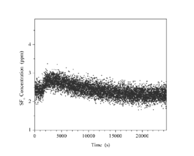
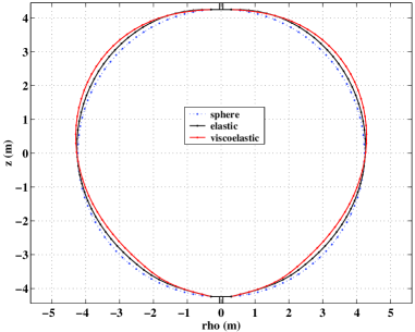 |
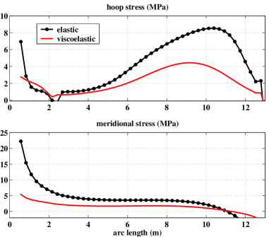 |
| 20% relative humidity | |
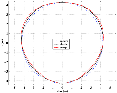 |
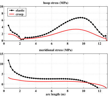 |
| 100% relative humidity | |