Conformal mapping of ultrasonic crystals: confining ultrasound and choclear-like wave guiding.
Abstract
Conformal mapping of a slab of a two-dimensional ultrasonic crystal generate a closed geometrical arrangement of ultrasonic scatterers with appealing acoustic properties. This acoustic shell is able to confine ultrasonic modes. Some of these internal resonances can be induced from an external wave source. The mapping of a linear defect produces a wave-guide that exhibits a spatial-frequency selection analogous to that characteristic of a synthetic “cochlea” . Both, experimental and theoretical results are reported here.
It has been recently reported that a parallel-sided slab of material with negative refractive index can work as a perfect lens Pendry1 and conformal transformations applied to these slabs generate a variety of lenses Pendry2 . Also, quite recently, curvilinear coordinate transformations and conformal mappings have been applied to versatile optic metamaterials in order to develop cloaks of invisibility Pendry3 . On the other hand, phononic crystals, i.e., periodic composite materials whose structure varies on the scale of the wavelength of the sound and exhibiting forbidden frequency band-gaps, have also stirred a great interest Sigalas ; Sala ; Montero ; Vasseur ; Psarobas ; Liu ; Yang1 . Here, we apply a conformal transformation to a slab of a conventional two-dimensional ultrasonic crystal to build a continuous field of ultrasonic scatterers that displays conspicuous physical results. Several acoustic properties of this transformed struture are studied theoretically and experimentally.
The analytic function using in this letter to generate the conformal mapping is , where , and ; belonging to the original complex plane and to the transformed one Nehari . This exponential function transforms parallel lines of the original slab into concentric circumferences. Since this continuous transformation preserves the angles between grid lines but not the size of the objects, the transmission spectra is disturbed in a complex way, displaying a lot of localized resonant modes. The similarity ratio in the transformed arrangement is locally equal to , preserving the filling ratio of the transformed unit cell and, hence, the effective medium parameters for the long wavelength limit Berryman are also conserved. This property is characteristic of conformal structures but is not fulfilled in the recently reported circular photonic crystals Horiuchi .
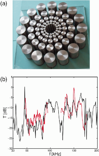
By applying the exponential conformal mapping to an adequate square periodic slab of identical circles, we generate the radial structure shown in Fig.1(a). Aluminum cylinders were glued to a methacrylate layer with 6 mm of thickness. Cylinders, with a height of 5 cm, were turned from bars of aluminum UNE 6082 (L 3453). The Young modulus of this material is = 6.9x10¹⁰ N/m2 and its density is = 2.7x10³ Kg/m3. These cylindrical scatterers were immersed in a large vessel, provided with anechoic walls, and filled with degasified water with a depth of 6 cm.
To measure the acoustic transmission through this shell of immersed cylindrical scatterers we emit with a Langevin type piezoelectric sandwich, built by using two PZT-5A piezoelectric rings. Te diameter of the is of =15.5 mm and the length, without coating, of = 33 mm. The launched signal is always received in a PVDF needle hydrophone DAPCO NP 10-3A90 and processed by means of a Hewlett Packard 4194A Impedance/Gain-Phase Analyzer. Theoretical calculations are carried out by solving the acoustic propagation equation by means of the Finite Element Method (FEM). We only present experimental measurements within the two broad resonance bands of the piezoelectric sandwich, ranging from 50 to 100 kHz and from 120 to 160 kHz respectively.
In Fig.1(b) we show both theoretical and experimental measurements of the outgoing transmission spectrum through the conformally mapped structure. The transmitter is now the transducer diametrically placed near the inner circular layer of scatterers and the receiver is the needle hydrophone located just at the output of the structure at the end of the corresponding emission radius. This measurement scheme is always chosen in order to profit the high directionality of the sandwich transducer, thus overcoming the high energy damping of the system.
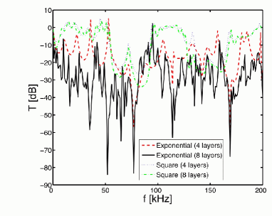
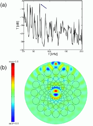
In Fig.2, transmission spectra FEM calculations for both the original square and its corresponding conformally mapped crystal slab are compared. Calculations are presented for slabs containing four and eight rows of scatterers respectively. The original ultrasonic crystals are excited by means of plane waves parallel to the slabs and transmission spectra are calculated by integrating the received signal after passing through the slabs. In the conformal structures the exciting waves are concentric circular waves launched from the inner of the cavities and their corresponding transmission spectra are calculated by integrating the received signal along a concentric circle enclosing the structures. The transmission spectra of the original slabs exhibit well defined forbidden frequency band gaps, as expected. On the contrary, the corresponding spectra for the transformed structures exhibit a spiky structure showing many deep peaks corresponding to internal resonances. The more of the layers in the circular shell the more peaks in the spectrum. Thus, these conformal structures can be used as ultrasonic traps to confine internal modes with a wide and discrete range of frequencies and as ultrasonic filters exhibiting very high attenuation for some frequency ranges. The present conformal device also allows to implement the important technique that consists of injecting inner resonances into the cavities of the shells starting from external point wave sources. Fig.3 (a) shows the ingoing transmission spectra for the conformal structure. The transmitter source is placed near the external boundary of the scatterer arrangement and the integrating receiver circular domain is located just at the center of the cavity. We have found a rich variety of inner localized modes injected from the external boundary. In Fig.3(b) we show an example of the injection of an internal resonance in the conformal shell.
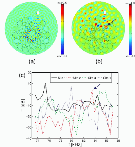
By removing a diagonal line along the direction in the original rectangular slab, a spiral-like defect is generated in the conformally mapped structure. In Fig.4(a) we show the guiding of the wave along these linear defects. There are a lot of resonance frequencies to localize the wave along these spiral choclear-like defects. In Fig.4(b) we show the experimental measurements performed at four different locations along the choclear-like defect generated in the conformal structure, where the numerical label of each curve indicates the relative location along the defect path, from the exterior to the interior. As it can be seen in the figure, a clear spatial- frequency selection is achieved. This performance allows us to identify this wave guide with a device similar to a “synthetic choclea”, which is able to discriminate and separate different frequencies by exploring the path along the defect with different point receptors for each resonance. So, the spiral-like defects works as the “Negative-print” or “mould” of a natural choclea. As an example, in Fig.4(c) we show the theoretically FEM calculated resonance of this choclear-like defect corresponding to a frequency of 83 kHz. As it can be seen, the theoretical prediction, indicated with a little arrow in Fig.4(b), fits with high accuracy a remarkable peak of the experimental observation shown in the second curve in Fig.4 (c). Theoretical and experimental concordance is observed also for the other resonance peaks.
As conclusion, a conformal mapping of ultrasonic crystals give rise to a variety of interesting acoustic transmission phenomena.
Acknowledgements.
This work has been partially supported by the Spanish MCYT (Grant No. FIS2004-03237), and the Mexican DGAPA-UNAM (Grant Nos. IN-117806 and IN-118406) and CONACyT (Grant No. D40615-F).References
- (1) J. B. Pendry, Phys. Rev. Lett. 85, 3966 (2000).
- (2) J. B. Pendry and S. Anantha Ramakrishna, J. Phys.: Condens. Matter 14, 8463 (2002).
- (3) J. B. Pendry, D. Schurig and D. R. Smith, Science 312, 1780 (2006); U. Leonhardt, ibid. 312, 1777 (2006).
- (4) M. M. Sigalas and E. N. Economou, J. Sound. Vib. 158, 377 (1992); Solid State Commun. 86, 141 (1993); M. S. Kushwaha, P. Halevi, L. Dobrzynski and B. Djafari-Rouhani, Phys. Rev. Lett. 71, 2022 (1993); M. S. Kushwaha, Int. J. Mod. Phys. B 10, 977 (1996).
- (5) R. Mártinez-Sala, J. Sancho, J. V. Sánchez, V. Gómez, J. Llinares and F. Meseguer, Nature (London) 378, 241 (1995); J. V. Sánchez-Pérez, D. Caballero, R. Martíinez-Sala, C. Rubio, J. Sánchez-Dehesa, F. Meseguer, J. Llinares, and F. Gálvez, Phys. Rev. Lett. 80, 5325 (1998).
- (6) F. R. Montero de Espinosa, E. Jiménez, and M. Torres, Phys. Rev. Lett. 80, 1208 (1998); M. Torres, F. R. Montero de Espinosa, D. García-Pablos and N. García, Phys. Rev. Lett. 82, 3054 (1999); D. García-Pablos, M. Sigalas, F. R. Montero de Espinosa, M. Torres, M. Kafesaki and N. García, Phys. Rev. Lett. 84, 4349 (2000); M. Torres, F. R. Montero de Espinosa and J. L. Aragón, Phys. Rev. Lett. 86, 4282 (2001).
- (7) J. O. Vasseur, P.A. Deymier, G. Frantziskonis, G. Hong, B. Djafari-Rouhani and L. Dobrzynski, J. Phys. Condens. Matter 10, 6051 (1998); J. O. Vasseur, P.A. Deymier, B. Chenni, B. Djafari-Rouhani, L. Dobrzynski and D. Prevost1, Phys. Rev. Lett. 86, 3012 (2001).
- (8) I. E. Psarobas, N. Stefanou and A. Modinos, Phys. Rev. B 62, 278 (2000).
- (9) Z. Liu, X. Zhang, Y. Mao, Y. Y. Zhu, Z. Yang, C. T. Chan and P. Sheng, Science 289, 1734 (2000).
- (10) S. X. Yang, J.H. Page, Z. Liu, M.L. Cowan, C.T. Chan and Ping Sheng, Phys. Rev. Lett. 88, 104301 (2002) and 93, 024301 (2004); M. Torres and F. R. Montero de Espinosa, Ultrasonics 42, 787 (2004).
- (11) Z. Nehari, Conformal Mapping (McGraw-Hill, New York, 1952).
- (12) J. B. Berryman, J. Acoust. Soc. Am. 68, 1809 (1980); A. Krokhin, J. Arriaga, L. N. Gumen, Phys. Rev. Lett. 91, 264302 (2003); J. Mei, Z. Liu, W. Wen and P. Sheng, Phys. Rev. Lett. 96, 024301 (2006); J. Li and C. T. Chan, Phys. Rev. E 70, 055602(R) (2004).
- (13) N. Horiuchi, Y. Segawa, T. Nozokido, K. Mizuno and H. Miyazaki, Opt. Lett. 29, 1084 (2004); J. Zarbakhsh, F. Hagmann, S. F. Mingaleev, K. Busch and K. Hingerl, Appl. Phys. Lett. 84, 4687 (2004); J. Chaloupka, J. Zarbakhsh and K. Hingerl, Phys. Rev. B 72, 085122 (2005).