ACORDE a Cosmic Ray Detector for ALICE
Abstract
ACORDE, the ALICE COsmic Ray DEtector is one of the ALICE detectors, presently under construction. It consists of an array of plastic scintillator counters placed on the three upper faces of the ALICE magnet. This array will act as Level 0 cosmic ray trigger and, together with other ALICE sub-detectors, will provide precise information on cosmic rays with primary energies around eV. In this paper we will describe the ACORDE detector, trigger design and electronics.
1 Introduction
Because of their extremely low flux, the observation of cosmic ray particles, with energies around and beyond the knee region, of the cosmic ray spectrum (see Fig. 1), is possible only using indirect methods. Ground based arrays, so-called extensive air shower arrays, located on the Earth surface or underground, detect particle showers created by the interaction of primary cosmic rays with the atmosphere. The large collecting surface of such arrays may allow the detection of events with extremely high energies and very high multiplicity. One of the main problem of an extensive air shower array experiment, comes from the difficulty in reconstructing the energy and the mass of the primary cosmic particle crossing the atmosphere. As matter of fact a detailed understanding of the interaction mechanism and and shower development and evolution in the atmosphere is needed in order to achieve this scientific goal. On the other hand new phenomena, in very forward high-energy hadronic interactions, such as coherent pion production, disoriented chiral condensate states (DCC) or heavy flavor production, may significantly affect the hadronic cascade and then the structure of the cosmic ray events at ground level. Such an effects may be responsible, for example, of the discrepancies found among different experiments, about the shower particle composition.
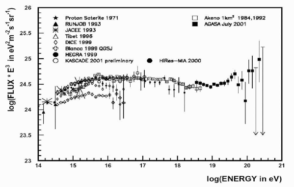
Particle production, both at large energies and in the forward direction, can be estimated only using models based on the extrapolation of accelerator data. The interpretation of cosmic ray data, in particular the identification of primary cosmic rays, rely crucially on such a model. Presently, there are no accelerator data for particle production at very small forward regions as well as in the energy region around the cosmic ray knee. In the past years, many interaction models such as VENUS, QGSJET, DPMJET, SIBYLL and others have been extensively developed and used by the cosmic-ray community [2]. As these models are based on proton-antiproton, electron-positron and heavy-ion collisions data, at the present, the maximum energy available from the accelerator experiments comes from the Tevatron collider that has TeV. LHC experiments may then contribute to clarify and constrain such a models significantly bringing the center-of-mass energy up to TeV which corresponds approximately to a proton of eV interacting with an other proton in the upper atmosphere. This energy value lies above the knee of the energy spectrum of cosmic rays, see Fig. 1. ALICE and the other LHC detectors will allow to extend the study of the -dependence in interactions to higher energies. Particularly important will be in particular to study nitrogen-nitrogen interactions, since nitrogen and oxygen are the most abundant nuclei in the atmosphere and since nitrogen nuclei are also present in high-energy cosmic rays (eV).
At CERN, the use of large underground high-energy physics experiments, for comic ray studies, has been suggested by several groups [3]. In particular, the L3 experiment established a cosmic ray experimental program the so called L3+Cosmics. The principal aim was to measure, precisely, the inclusive cosmic ray () spectrum in the energy range GeV [4], which is relevant for neutrino oscillations.
2 The ACORDE Detector
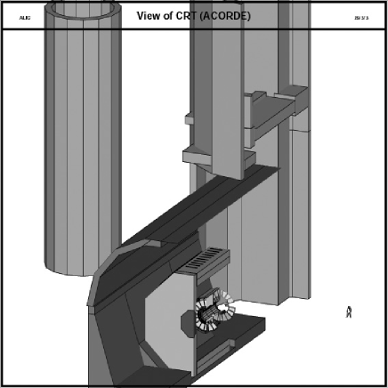
ALICE is an experiment mainly designed to study the products of nucleus-nucleus collisions at CERN Large Hadron Collider (LHC) [5]. The underground location of the ALICE detector, with 30 m of overburden composed of subalpine molasse, is an ideal place for muon based underground experiments (see Fig. 2). Using this facilities, we plan to observe muon bundles generated by cosmic ray primary particles with energies around the knee region eV [6].
ACORDE, ALICE COsmic Ray DEtector, is an array of scintillator modules that will act as cosmic ray trigger for ALICE calibration, as a multiple muon trigger and it will be used to detect, in combination with other tracking apparatus, atmospheric muons and multi-muons events. Taking into account the fine granularity of the ALICE Timing Projection Chamber (TPC) and the fast response of the ACORDE array it will be possible to measure several properties of cosmic ray events with high density muon tracks, the so-called muon bundles. A more detailed discussion on the ACORDE physics goals can be found in the ALICE Physics Performance Review, Chapter 6 [5].
2.1 The scintillator array
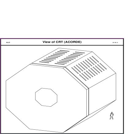
ACORDE is an array of plastic scintillator modules (60 at the present) placed on the top sides of the central ALICE magnet, as shown in Fig. 3. More modules, to achieve a better angular coverage and acceptance, will be added later. Each module, consists of two plastic scintillator paddles with cm2 effective area, arranged in a doublet configuration (see Fig. 4). Each doublet consists of two superimposed scintillator counters, with their corresponding photomultipliers active faces, looking back to back. A coincidence signal, in a time window of ns, from the two scintillator paddles gives, for each module, the trigger hit. A PCI BUS electronics card have been developed in order to measure plateau and efficiency of the module counters [7].
2.2 The Cosmic Ray Trigger
The cosmic ray trigger system (CRT) will provide a fast level-zero trigger signal to the central trigger processor, when atmospheric muons impinge upon the ALICE detector. The signal will be useful for calibration, alignment and performance studies of other ALICE tracking detectors: the Time Projection Chamber (TPC), the Transition Radiation Detector (TRD) and the Inner Tracking System (ITS). A typical rate, for single atmospheric muons crossing the ALICE cavern, will be less than Hz/m2. The expected rate for multi-muon events will be around or less than Hz/m2. Atmospheric muons will need an energy of at least GeV to reach the ALICE hall, while the upper energy limit for reconstructed muons in the TPC will be less than 2 TeV, depending on the ALICE magnetic field intensity (up to T).

2.3 Electronics design and construction
We have designed and implemented the necessary electronics in order to do the following tasks:
-
1.
Perform the clock synchronization with the LHC clock;
-
2.
Produce single and multi-muon trigger signals for the Central Trigger Processor (CTP);
-
3.
Prodce a wake-up signal for the ALICE-TRD;
-
4.
Communicate with the DAQ through a DAQ Source Interface Unit;
-
5.
Online monitoring of the scintillator counter performances.
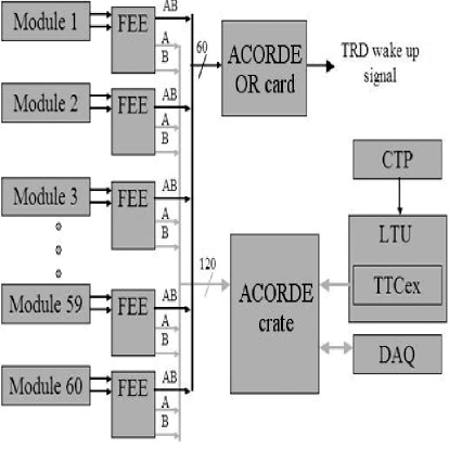
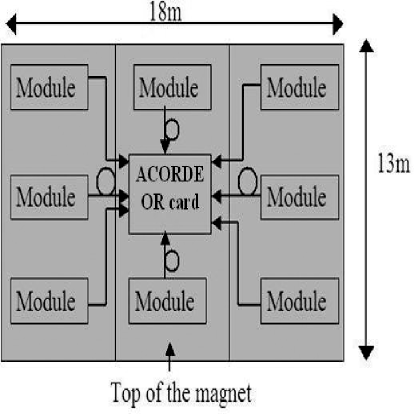
The ACORDE Electronics is then made of several different parts essentially the follow: 60 Front End Electronics cards (FEE), one for each ACORDE module; the ACORDE OR card to generate the TRD wake up signal (this card receive the 60 coincidence LVDs signals coming from the FEE cards); a Main Card, which contains the electronics to receive the 120 LVDS signals coming from 120 scintillators (this card will produce the single and the multi-coincidence trigger signals and will provide the connectivity to the ALICE trigger and DAQ systems, see Fig. 5.a).
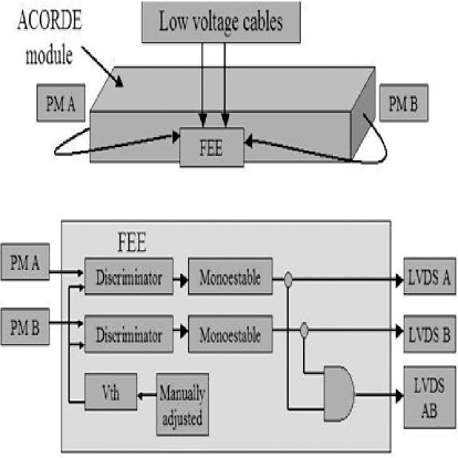
Between the electronics cards the FEE performs the following task: take the signal from each of the two PMT contained in an ACORDE module and submits it to a leading edge discriminator. The discriminators convert the negative low signal coming from each PMT to a CMOS digital signal. These signals have a time duration of about 10-20ns. In order to produce a wider signal (100ns) the FEE electronics includes a mono-stable circuit. The mono-stable outputs are used to produce the coincidence (AND) between the two plastic scintillators. Also, the FEE electronics translate these three signals into LVDS signals to eliminate noise problems during the transmission to the other cards. Summarizing, the FEE will be able to provide the coincidence signal of one ACORDE module and two signals coming from the scintillators, these three signals will be pulses of 100ns. The coincidence signals are then transmitted to the ACORDE ”OR” card and the PMT signals are tranfered to the ACORDE main card (see Figure 5.b). The ACORDE OR card is used to produce a TRD wake-up signal using the coincidence signals coming from the 60 FEE cards. Those signals are then translated from LVDS to CMOS levels. Afterwards, it will be used an OR gate of 60 inputs to generate the wake-up signal. The trigger signal is then translated from CMOS to LVDS in order to be sent to the TRD detector. There is also a 40MHz cryptal oscillator to produce the wake-up signals (25ns LVDS pulse). The ACORDE OR card will be located on top of the magnet as shown in Fig. 6.a.
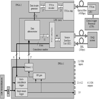
The ACORDE main card uses 1 Bus card to interconnect 6 LVDS to CMOS translator cards with the ACORDE main card. One LVDS to CMOS translator card is able to receive 20 differential signals coming from 20 FEE cards. In order to receive the 120 differential signals we use six translator cards. The Bus card supply the power to the 6 translator cards and the ACORDE main card. The last card receives 120 CMOS signals through the bus card. These signals are supplied to an ALTERA EP20K100QC240-1 FPGA. This FPGA chip same as the one used in the TPC electronics; tests done previously have shown that this device is radiation tolerant. The function of the FPGA chip is to store the hit information and produce the single muon and the multi-coincidence trigger in synchronization with the LHC clock signal. The main card has a second ALTERA EP20K100QC240-1 FPGA chip, this device is connected with the TTCrq and SIU card to provide the LHC clock recovery, the trigger message decoder, the data header generator and the ACORDE-SIU interface. The single moun L0 trigger signal is generated by combinational logic (AND and OR gates). The ACORDE card latches the tracking data in a memory when the detector produces a L0 trigger signal. The SIU daughter card allows the communication with the DAQ system to be able to send the data header and the tracking information through the Detector Data Link (DDL). The ACORDE card sends the Data header and the tracking data to the DAQ system after receiving a L2 accepted trigger message, see Fig. 6.b. The FEE cards has been tested showing a very good performance, the leading edge discriminator has a rise and fall time of 2ns and the mono-stable circuit produces a 100ns pulse.
In order to calibrate the ALICE-TPC detector using cosmic rays, we have developed a different version of the ACORDE electronics. This version only receives 40 differential signals coming from 20 modules. Ten modules will be located on top and the other ten will located underneath. The system will use an ACORDE card with one bus card to connect two LVDS to CMOS translator cards to 1 main card. This card will only use one ALTERA EP20K100QC240-1 FPGA chip. We will not have connection to the Trigger and DAQ ALICE systems. This electronics will provide a trigger signal (LVDS). The user will be able to set an arbitrary OR combination of the top modules in AND with an arbitrary OR combination of the bottom modules through a PC. The communication between the PC and the ACORDE electronics card is provided through the parallel port of the PC. An ACORDE-PC interface card with a micro-controller has been developed to receive the data from the PC to show the setting combination with a group of 20 LED indicator. In this way the user can verify if the system have the correct configuration.
3 The ACORDE Control System
The main tasks of any Detector Control System (DCS) is the
monitoring and control of the electrical and physical parameters
necessary to operate the sub-detector. In general, these task include the high voltage (HV) and low voltage (LV) power supplies,
the front-end electronics (FEE) configuration parameters, alarm handling,
parameter archiving and all other services such as gas, cooling, etc.
In our case we need to monitor and control only the HV and LV power supplies.
The electronics parameters such as multi-coincidence number, trigger rates
and others will be managed by the central DAQ system.
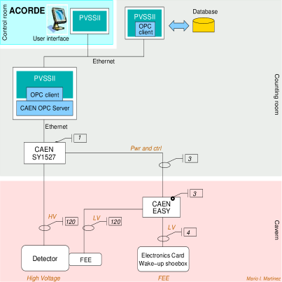
A general view of our DCS is shown in Fig. 7.a. We plan
to use the SY1527 and the EASY [8] (Embedded
Assembly SYstem) power supply systems from CAEN as
the HV and LV supplies respectively. The latter is a radiation- and
hig-magnetic-field tolerant power supply system to be installed in the
cavern racks to supply the LV for ACORDE.
The SY1527 crate can hold up to 16 boards. Ten of its slots will be
filled with 12-channel HV boards (A1733N) to feed the 120 PMT’s. We
will also install the EASY Branch Controller (A1676A) board that can
control up to 6 EASY crates. We will need two full EASY 3000 crates
each with five 12-channel 2–8 V boards (A3009) for the discriminators.
The remaining four channels for the Acorde Electronics Card and the
shoebox producing the TRD wake up signal will be hosted by a third
EASY 3000 crate with an additional A3009 board.
The intrinsic grouping of the scintillators into modules (each with
a couple of scintillators and PMT’s) and the fact that the FEE cards
will be mounted on the modules, makes it natural to select a
detector-oriented hierarchy for our DCS as shown in
Fig. 7.b. This hierarchy will allow us to independently
control a single module in a simple way which can be useful for
purposes of isolating, testing or calibrating it. There will be a total of 183 Control Units (CU) in the DCS; the
parent ACORDE DCS with 61 module CU’s (M0 through M60). M1 to
M60 will control each one of the modules respectively, including its
associated FEE card. Module 0 will take care of the LV supply to the
Electronics and TRD shoe-box cards.

As mentioned before the only electronics parameter to be controlled is the multi-coincidence number; i. e. the minimum number of modules hit in order to produce a multi-muon event trigger. This threshold will be programmed through the DAQ system. The DCS however should be able to monitor and control it (via the DAQ system). As described on the ALICE TDR 010 [9] the online systems interface to each other through the Experiment Control System (ECS); so the DCS will access the multi-coincidence number by communicating with the ECS. The DCS is also in charge of managing the calibration procedure of our detector. This procedure will consist in monitoring the individual counts on each one of the scintillators in a given time interval; so that we can realize if any of the corresponding efficiencies has dropped to an unacceptable value.
4 Summary
We have implemented a dedicated cosmic ray trigger for ALICE which in conjunction with other ALICE detectors provides a powerful tool for the study of muon bundles properties. At the present, we have 20 ACORDE modules already installed and the related electronics working. The ALICE-TPC above ground commissioning is proceeding based on ACORDE trigger using 10 modules placed on the top and 10 underneath the ALICE TPC (see [10]).
5 Acknowledgments
We are grateful to the High Energy Physics Latinamerican-European NETWORK (HELEN) and CONACyT(México) for continuous support. We especially thank Laszlo Jenkovszky for his kind hospitality.
References
- [1] M. Takeda, et. al. (AGASA Collaboration),Energy determination in the Akeno Giant Air Shower Array experiment astro-ph/0209422.
- [2] J. Ranft, Cosmic Ray particle production, Nucl. Phys. B Proc. Suppl., 71, 228, 1999.
- [3] A. C. et al., The UA1 detector as possible cosmic ray device, Proc. 17th Int. Cosmic Ray Conf., Paris, 10, 401, 1981; C. Taylor et al., CosmoLep, an underground cosmic ray muon experiment in the LEP ring, CERN/LEP C 99-5, LEPC/P9, 1999; C. Taylor et al., CosmoLep, an underground cosmic ray muon experiment in the LEP ring, CERN/LEPC 99-5, LEPC/P9, 1999;
- [4] O. Adriani, et. al. (L3 + C Collaboration), NIMA, 488, (200 2) pp. 209-225.
- [5] ALICE Physics Performance Report, ALICE Collaboration, http://alice.web.cern.ch/Alice/ppr/.
- [6] A. Fernández et al.,Czechoslovak J. Phys., 55 (2005) B801 - B807.
- [7] E. H. Bellamy et al., Nucl. Instrum. Meth. A 343, 484 (1994); E. H. Bellamy et al., Nucl. Instrum. Meth. A 339, 468 (1994).
- [8] CAEN S.p.A. – Costruzioni Apparecchiature Elettroniche Nucleari, http://www.caen.it/nuclear/easy_ info.html
- [9] ALICE Technical Design Report of the Trigger Data Acquisition High-Level Trigger and Control System, CERN-LHCC-2003-062, 7 january 2004, chap. 16, 20.
- [10] C.Pagliarone et al., arXiv:physics/0606051 to be published on Nucl. Instrum. Meth.