Further author information: A.V.K. is on leave from Department of Physics, State Maritime Technical University, St. Petersburg, Russia. A.V.S. is on leave from Ioffe Physical-Technical Institute, Russian Academy of Sciences, St. Petersburg, Russia.
Parameters of the crystalline undulator and its radiation for particular experimental conditions
Abstract
We report the results of theoretical and numerical analysis of the crystalline undulators planned to be used in the experiments which are the part of the ongoing PECU project[(1)]. The goal of such an analysis was to define the parameters (different from those pre-set by the experimental setup) of the undulators which ensure the highest yield of photons of specified energies. The calculations were performed for 0.6 and 10 GeV positrons channeling through periodically bent Si and Si1-xGex crystals.
keywords:
crystalline undulator, dechanneling, photon attenuation1 INTRODUCTION
In this paper we report the results of calculations of the parameters of the crystalline undulators (different from those pre-set by the experimental setup, see Section 2) and the characteristics of the undulator radiation for the positron energies, the types and lengths of the crystals, and the photon energies which will be available in the experiments planned to be carried out within the PECU project[(1)].
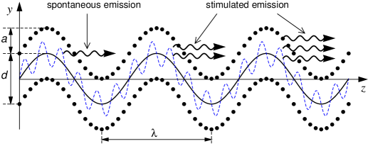
A periodically bent crystal together with a bunch of ultra-relativistic charged particles which undergo planar channeling constitute a crystalline undulator, see Fig. 1. In such a system there appears, in addition to the well-known channeling radiation, the undulator type radiation which is due to the periodic motion of channeling particles which follow the bending of the crystallographic planes[(2), (3)]. The intensity and characteristic frequencies of this radiation can be varied by changing the beam energy and the parameters of the bending. In the cited papers as well as in subsequent publications (see the review Ref. 4 and the references therein) we proved a feasibility to create a short-wave crystalline undulator that will emit high-intensity, highly monochromatic radiation when pulses of ultra-relativistic positrons are passed through its channelsElectronUndul . A number of corresponding novel numerical results were presented to illustrate the developed theory, including, in particular, the calculation of the spectral and angular characteristics of the new type of radiation. Later the importance of the novel concept of a crystalline undulator has been realized by other authors.
The scheme presented in Fig. 1 leads also to the possibility of generating a stimulated emission of a free-electron laser type. The estimates carried out in Refs. 3; 4; 7 showed that it is feasible to consider emission stimulation within the range of photon energies keV (a Gamma-laser). It was demonstratedSPIE1 also that the brilliance of radiation from a positron-based undulator in the energy range from hundreds of keV up to tens of MeV is comparable to that of conventional light sources (both existing and proposed) operating for much lower photon energies.
Once the feasibility of a positron-based crystalline undulator had been established theoretically, it has become clear that further joint theoretical and experimental efforts are needed to actually create this powerful source of radiation, the parameters of which can be easily tuned by varying the energy of the beam particles, by using different crystals and by changing the parameters of the crystal bending. All this constitute a complex, highly interdisciplinary, absolutely new and very promising field of research. Constructing such a device is an extremely challenging task, to realize which it is necessary to bring together research groups from various fields of expertise. Such a collaboration, created recently, has got the support from the European Commission within the framework of the PECU projectPECU .
The PECU project aims to develop in full the theory of of spontaneous and stimulated emission of radiation in crystalline undulator, to use both theory and experiment to investigate the best methods and materials for constructing the crystals, to carry out the experiments with the crystalline undulators. The European researchers, involved in the project, are among the world leaders in various fields of research. Theoretical support of the activities within the project will be carried out by researches from Frankfurt Institute for Advanced Studies and Institut für Theoretische Physik (Univestität Frankfurt am Main), whose pioneering works initiated the worldwide activity in the field. The key role in channeling experiments will be played by scientists from the Aarhus University (Denmark), who have a long-term experience in beam physics and studying the channeling phenomenon. Also, this institution has the necessary facilities to construct periodically bent crystalline structures. The group from Mainz University (Germany) will carry out experiments on testing periodically bent structures. The group from Imperial College (the UK) will contribute its expertise in the free-electron laser physics. The experiments with crystalline undulators will be performed at CERN and INFN, where the positron beams, satisfying all the necessary criteria, are available.
For further referencing, let us mention the necessary conditions, which must be met in order to treat a crystalline undulator as a feasible scheme for devising a new source of electromagnetic radiation KSG1998 ; KSG1999 ; KSG2004_review :
| (1) |
Below we present a short description of the physics lying behind these conditions.
Stable channeling of an ultra-relativistic positron in a periodically bent channel is possible if the maximum centrifugal force is less than the maximal interplanar force , i.e. . Expressing through the energy of the projectile, the period and amplitude of the bending one formulates this condition as it is written in (1).
The operation of a crystalline undulator should be considered in the large-amplitude regime. Omitting the discussion (see Ref. 2; 3; 4), we note that the limit accompanied by the condition is mostly advantageous, since in this case the characteristic frequencies of undulator and channeling radiation (see, e.g., Ref. 8) are well separated, so that the latter does not affect the parameters of the former, whereas the intensity of undulator radiation becomes comparable or higher than that of the channeling oneKSG1998 ; KSG1999 ; KKSG00Tot . A strong inequality , resulting in elastic deformation of the crystal, leads to moderate values of the undulator parameter (here ) which ensure that the emitted radiation is of the undulator type rather than of the synchrotron oneBaier .
The term ’undulator’ implies that the number of periods is large (here denotes the crystal length). In this case the emitted radiation bears the features of the undulator one, i.e. narrow, well-separated peaks, - harmonics, in spectral-angular distribution. Therefore, the stronger the third inequality is the more pronounced the features are.
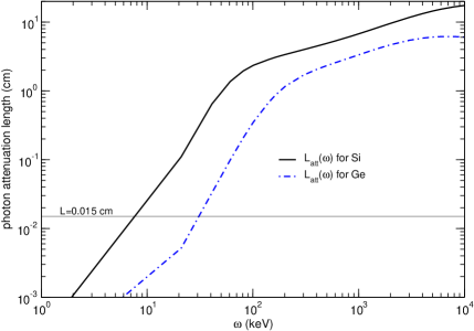
The essential difference between a crystalline undulator and a conventional one, based on the action of a magnetic (or electric) fieldRullhusenArtruDhez , is that in the latter the beams of particles and photons move in vacuum whereas in the former – in a crystalline medium, where they are affected by the dechanneling and the photon attenuation. The dechanneling effect stands for a gradual increase in the transverse energy of a channeled particle due to inelastic collisions with the crystal constituentsLindhard . At some point the particle gains a transverse energy higher than the planar potential barrier and leaves the channel. The average interval for a particle to penetrate into a crystal until it dechannels is called the dechanneling length, . In a straight channel this quantity depends on the crystal, on the energy and the type of a projectile. In a periodically bent channel there appears an additional dependence on the parameter . The intensity of the photon flux, which propagates through a crystal, decreases due to the processes of absorption and scattering. The interval within which the intensity decreases by a factor of is called the attenuation length, . This quantity is tabulated for a number of elements and for a wide range of photon frequencies (see, e.g., Ref. 13). The forth condition in (1) takes into account severe limitation of the allowed values of the length of a crystalline undulator due to the dechanneling and the attenuation.
Finally, let us comment on the last condition in (1). For sufficiently large photon energies ( keV) the restriction due to the attenuation becomes less severe than due to the dechanneling effectKSG1998 ; KSG1999 ; KSG2004_review . Then, introduces an upper limit on the length of a crystalline undulator. Indeed, it was demonstratedSPIE1 ; Dechan01 that in the limit the intensity of radiation is not defined by the expected number of undulator periods but rather is formed in the undulator of the effective length . Since for an ultra-relativistic particle BiryukovChesnokovKotovBook ; Uggerhoj_RPM2005 ; Baier , it seems natural that to increase the effective length one can consider higher energies. However, at this point another limitation manifests itselfKSG1998 ; KSG1999 ; KSG00Loss . The coherence of an undulator radiation is only possible when the energy loss of the particle during its passage through the undulator is small, . This statement together with the fact, that for an ultra-relativistic projectile is mainly due to the photon emissionBaier , leads to the conclusion that must be much smaller than the radiation length , - the distance over which a particle converts its energy into radiation.
For a positron-based crystalline undulator a thorough analysis of the system (1) was carried out for the first time in Refs. 2; 3; 6; 9; 17; 4. For a number of crystals the ranges of , , and were established within which the operation of the crystalline undulator is possible. These ranges include GeV, , , keV and are common for all the investigated crystals. The importance of exactly this regime of operation of the positron-based crystalline undulator was later realized by other authorsBellucciEtal2003 .
2 EXPERIMENTAL CONDITIONS
At the initial stage of the PECU projectPECU two experiments on the measurement of the photon yield from positron-based crystalline undulators are planned to be carried out at CERN and INFN laboratories. Due to the experimental conditions and methods of preparations of periodically bent crystalline structures several parameters of the crystalline undulator are pre-set. These parameters includeUggerhoj2006 :
-
•
The positron beam energy is fixed at MeV in the INFN experiment and at GeV in the CERN one.
-
•
The crystalline undulators are to be produced by two methods. The first method utilizes the technology of growing Si1-xGex structures. In this case, by varying the Ge content one can obtain periodically bent crystalline structure MikkelsenUggerhoj2000 ; Darmstadt01 . The technological restrictions imposed by this method on the crystalline undulator length is that m.
The periodic bending can also be achieved by making regularly spaced grooves on the crystal surfaceBellucciEtal2003 . In this case, the crystalline planes in the vicinity of the defects become periodically bent. For the experiment within PECU a number of Si crystals prepared by laser-ablation method are availableUggerhoj2006 ; Connell2006 . The length of such crystalline undulators is or 4 mm, and the period of the structure is 50, 100 and 200 m. -
•
A severe restriction on the emitted photon energy is anticipated in the INFN experiment where the experimental setup allows to register only keV photons.
Theoretical support for these experiments implied to provide an initial analysis of other parameters which can be varied in the crystalline undulators described above, and, as a final result, to establish the ranges of parameters which lead to the highest yield of the undulator radiation. Partly, the results of such analysis we present in sections 3.2 and 3.3 for the following two cases (labeled below in the paper as ’Undulator 1’ and ’Undulator 2’):
| Undulator 1.The fixed parameters are: | (2) | ||||
| Undulator 2.The fixed parameters are: | (3) |
3 RESULTS OF CALCULATION
3.1 The formalism
For the sake of reference let us outline the basic formulae which we used in our calculations. A more detailed description of the formalism one can find in Refs. 3; 4; 6; 14.
The spectral distribution of the energy of radiation emitted in a crystalline undulator in the forward direction (i.e., with respect to the axis, see Fig. 1) can be written in the following formSPIE1 :
| (4) |
where is the fine structure constant, , is the Anger’s functionGradshteyn , with being the undulator parameter. The parameter is related to the frequency of the emitted radiation as follows
| (5) |
where is the undulator frequency. The integer values of , i.e. define the frequencies of harmonics. The factor on the right-hand side of (4) ensures that only odd harmonics are emitted in the forward direction. We also note that in this case the Anger’s functions reduce to the Bessel functions (e.g., Ref. 23), so that the expression in the square brackets acquires the form known in the theory of undulator radiationBaier ; Alferov .
A peculiar feature of the undulator radiation, which clearly distinguishes it from other types of electromagnetic radiation by a charge moving in external fields, is that for each value of the emission angle (and, in particular, for ) the spectral distribution consists of a set of narrow and equally spaced peaks corresponding to different harmonics. In an ideal undulator (i.e., in which positrons and photons propagate in vacuum) the peak intensity is proportional to the squared number of periods. Formally, it follows from the fact that is proportional to which behaves as for Baier ; Alferov . This factor reflects the constructive interference of radiation emitted from each of the undulator periods and is typical for any system which contains coherent emitters. Consequently, in an ideal undulator one can, in principle, increase unrestrictedly the radiated intensity by increasing of the undulator length which, for a fixed , defines the number of undulator periods.
The situation is different for a crystalline undulator, where the number of channeling particles and the number of photons which can emerge from the crystal decrease with the growth of . In Ref. 6; 14 we analyzed quantitatively the influence of the dechanneling and the photon attenuation on the spectral-angular distribution. The main result of these studies reads that the peak intensity of the radiation is no longer proportional to . Omitting the discussion, which can be found in the cited papers, we mention that in a crystalline undulator the factor must be substituted with , which depends not only on and but also on the ratios and . A convenient formula for is as followsSPIE1 :
| (6) | |||||
where , and is a positive integer such as . Despite a cumbersome form of the right-hand side of (6) its main features can be easily understood. The most important is that, as in the case of an ideal undulator (to which reduces in the limit ) the main maxima of correspond to the integer values of , and, therefore, the harmonic frequencies are still defined by (5) with . For finite and the maximum value of is smaller than whereas the width of the peak is larger than that in the corresponding ideal undulator.
To complete the descriptive part of the paper let us mention the method used to calculate the dechanneling and the attenuation length.
The dechanneling length in a periodically bent crystal is expressed via the dechanneling length in the straight crystal as followsKSG1999 ; SPIE1 :
| (7) |
Here is the interplanar distance, is the Thomas-Fermi radius of the crystal atom. The quantity , with denoting the (average) ionization potential of the crystal atom, is the Coulomb logarithm characterizing the ionization losses of an ultra-relativistic positron in an amorphous medium. On the right-hand side of the second equation it is implied that is measured in GeV, and - in Å, and the result, , - in cm. The data on for several straight channels are presented in Table 1.
| GeV | GeV | |||||
|---|---|---|---|---|---|---|
| Channel | (100) | (110) | (111) | (100) | (110) | (111) |
| Si | 0.029 | 0.041 | 0.050 | 0.43 | 0.61 | 0.74 |
| Ge | 0.025 | 0.033 | 0.043 | 0.36 | 0.51 | 0.63 |
The data on the attenuation lengths for various crystals can be found in Ref. 25. The dependence for Si and Ge in a wide range of photon energies is presented in Fig. 2.
Finally, we mention that the values of and for a composite crystal Si1-xGex can be estimated as follows:
| (8) |
Since it is anticipated that the Ge content is small, namely , the values of for the composite are, practically, the same as for pure Si structure.
3.2 Numerical results for ’Undulator 1’.
The goal of the quantitative analysis of the undulator with fixed values of , and (see eq. (2)) was to establish the ranges of other parameters (these include, in particular, the number of periods , the bending amplitude , and the parameter ) which ensure the largest photon yield. The results of this analysis are presented in Figs. 3-5. The calculations were organized as follows.
As a first step, let us consider the undulators with different number of periods, . The value of defines the period length: . For fixed , and the first relation from (1) uniquely defines the dependence of on , and, as direct consequence, the dependence of on :
| (9) |
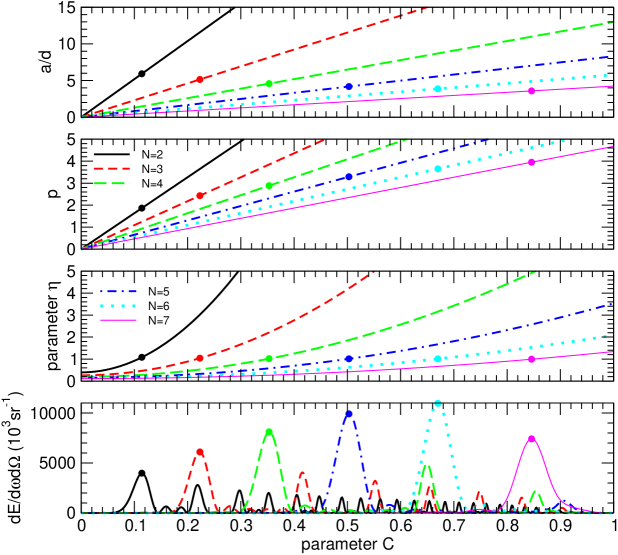
where and are the absolute maximum values of the amplitude and undulator parameter achieved at and . The dependences and are presented in Figs. 3(a)-(b). Fig. 3(c) presents the dependence of the parameter on which, as it follows from (5), has the form and for each reaches its maximum value at , .
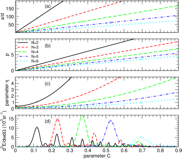
Graphs (a) and (b) represent the dependences and , - see (9). Graph (c) - represents , with defined in (5). The dependence of (see (4)) on is presented in graph (d). Open circles mark the parameters which correspond (for each ) to the main maxima of .
Eq. (9) and figs. 3(a)-(c) show that generic type of each of the functions, - , or , is independent on , so that in each graphs the curves for different differ only quantitatively (for fixed the larger values of , and correspond to the smaller ’s).
These quantities, being used in (4), allow one to analyze the dependence of the energy emitted at given frequency in the forward direction on and , see Fig. 3(d). Let us mention several features of the functions and relate them to other graphs presented in Fig. 3. Firstly, comparing the graphs (d) and (c) one notices that for each the (most pronounced) maxima are located at those -values which correspond to , whereas for even the spectrum in accordance with general theory of the planar undulator radiation. The maximum value of is much larger than one for but in the case . As a result, the number of the maxima of decreases with . The open circles in Fig. 3(d) mark the highest (for a given ) peak. It is seen that the position of the highest peak gradually shifts towards larger values as increases. This feature reflects the fact that for each the highest peak corresponds to , which is achieved at larger ’s as grows, - Fig. 3(c). The height of the peak exhibits a non-monotonous dependence on . One one understands this feature recalling eqs. (4)-(7). From the first of these it follows that with the latter tending to increase with , - note the factor on the r.h.s. of (6)). However, as becomes larger the dechanneling lengths , eq. (7), decreases, so that the exponential factors reduce . Therefore, there exists a particular number of undulator periods which ensures the absolute maximum of the photon yield. For the undulator with fixed values of , and (see eq. (2)) the absolute maximum is achieved for and . The corresponding values of the amplitude and undulator parameter are , (see Fig. 3(a,b)).
Figs. 4(a)-(d) present spectral distribution , - eq. (6), as a function of photon energy within the interval including keV and calculated for different values. For each the calculations were performed for the parameters and indicated in Fig. 3 by open circles. The solid curves were obtained with the dechanneling and photon attenuation effects taken into account. For the sake of comparison, the dashed curves represent the spectral distributions in the absence of these effects. The destructive role of these effects is clearly seen: the maxima of the solid curves are noticeably lower than those of the dashed curves.
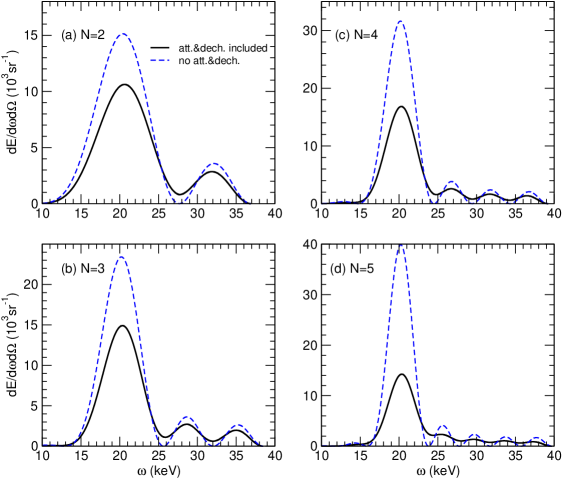
(a) , , , , m; (b) , , , , m;
(c) , , , , m; (d) , , , , m.
The data presented in Figs. 3 and 4 illustrate the procedure, following which one define the optimal parameters of the crystalline undulator (with pre-set values of , and ) in order to achieve the highest yield of the emission of the energy 20 keV. However, the values of the undulator parameter in all four cases described in the caption to Fig. 4 indicate that for keV one can expect higher values of the spectral intensities . Indeed, as it follows from general theory of undulator radiation (see, e.g., Baier ), in the case the number of emitted harmonics is and the intensity of emission into the fundamental harmonic is not the highest one. To illustrate this statement in Fig. 5 we present the results of calculation of (eq. (4)) over the wide range of photon energies. In each graph from this figure the characteristics of the undulator (, , and ) are as in the graph with the same from Fig. 5. The harmonic-like character of the spectral distribution manifests itself in each graph, although it becomes more pronounced with the increase of : the number of the emitted harmonics (peaks) in Fig. 5(d) exceeds that seen in graph 5(a) by a factor approximately equal to the cubed ratio of the corresponding undulator parameters ( and , see Fig. 4). The figure demonstrates also that the undulators, initially ’tuned’ to the emission of keV, can be used to generate more energetic radiation and of a higher intensity.
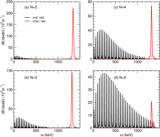
The energy of the harmonic of a sufficiently large order might become comparable with the characteristic energy of the channeling radiationKumakhov2 . Therefore, it is meaningful to compare the spectra of the undulator and the channeling radiation. In Fig. 5 powerful and wide peaks in the region MeV represents the spectral distribution of the channeling radiation. The latter was calculated using harmonic approximation for the interplanar potential. Omitting the detailed discussion (see Ref. 17) let us briefly explain the decrease with . Qualitatively, is proportional to the (average) squared amplitude of the channeling oscillations, . In the straight channel . In a periodically bent channel, the depth of the effective potential well decreases, leading to the decrease of the amplitudes of the channeling oscillations. Within the framework of the harmonic approximation BiryukovChesnokovKotovBook ; KSG00Loss . Therefore, - decreases with . Fig. 5(a) corresponds to the undulator with the smallest value of , whereas Fig. 5(d) - to the one with the largest (see Fig. 3(d) or/and the caption to Fig. 4). This explains the difference in the magnitudes of the channeling peaks.
3.3 Numerical results for ’Undulator 2’.
The results of numerical analysis of the second undulator, - eq. (3), are presented in Figs. 6-8 The calculations were performed following, basically, the scheme outlined in Sec. 3.2, though there were several specific features.
Firstly, the energy of radiation was not limited by experimental conditions. Therefore, it was meaningful to analyze the radiation within the range keV where the photon attenuation becomes much less pronounced, see Fig. 2. The data presented below refer to the undulator tuned to the first harmonic energy MeV. The corresponding attenuation length is nearly three orders of magnitude larger than the crystal length m. Therefore, the photon attenuation can be completely disregarded. (In formal terms this means that one can put on the right-hand side of (6).)
Secondly, the length of Undulator 2 only slightly exceeds that of Undulator 1, whereas the beam energy, GeV, is nearly 20 times higher. As a result, the dechanneling length becomes more that an order of magnitude larger than the crystal length (see Table 1). Therefore, one may expect that a strong inequality will be valid over a wide range of the bending parameter leading to a decrease of the influence of the dechanneling effect on the photon yield.
Graphs (a) and (b) represent the dependences and , - see (9). Graph (c) - represents , with defined in (5). The dependence of (see (4)) on is presented in graph (d). Circles mark the parameters which correspond (for each ) to the main maxima of .
Figs. 6(a)-(d) present the dependences , , (see (9)) and - the energy emitted in the forward direction, calculated for several values of the number of undulator periods. General features of all dependences are similar to those presented in Figs. 3. The qualitative differences are mostly pronounced for the dependences: it is seen that the values in Fig. 6(a) are by more than an order of magnitude smaller than those in Fig. 3(a). This is solely due to the differences in the crystal length and the beam energy. Indeed, the factor (see(9)) for Undulator 2 is approximately 15 times less than for Undulator 1. On the contrary, the factor is independent on , and this results in close values of for both undulators. The peak intensities of in Fig. 6(d) are three orders of magnitude higher than those in Fig. 3(d). This increase is due to the following two reasons. Firstly, the factor on the r.h.s. of (4) ensures the increase by more than 2 orders of magnitude. The rest is donated by the enhancement of the factor due to the decrease of the ratios and .
Six graphs in Fig. 7 present spectral distribution of the radiation in the forward direction as a function of photon energy within the interval including MeV and calculated for different values. For each the calculations were performed for the parameters and marked in Fig. 6 by the circles. The solid and dashed curves were obtained with and without account for the positron dechanneling (the attenuation is negligibly small for a 5 MeV photon). As mentioned above, the influence of this effect in the case of Undulator 2 is much less pronounced that for Undulator 1 (see Fig. 4). Only in the two last graphs for and the account for the dechanneling results in a noticeable decrease of the photon yield. These cases correspond (see the caption) to large values of the parameter which, in turn, greatly reduces the dechanneling length (see eq. (7)) making it comparable or even less than the length of the crystal.
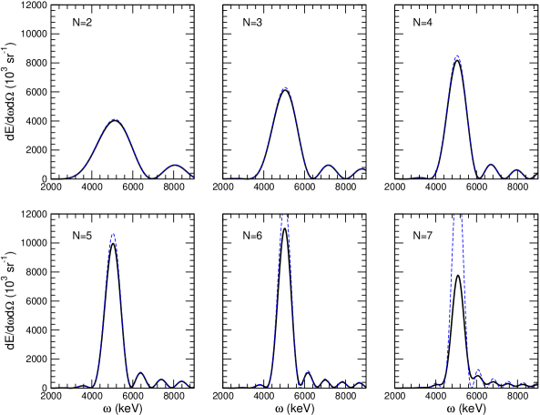
(a) , , , , m; (b) , , , , m;
(c) , , , , m; (d) , , , , m;
(e) , , , , m; (f) , , , , m.
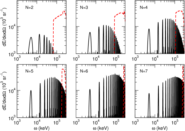
Finally, let us shortly comment on the graphs from Fig. 7 which present the spectra over the wide range of photon energies calculated for the undulators with the parameters enlisted in the caption to Fig. 7. Note the double log scaled used in this figure in contrast to its analogue for Undulator 1, - Fig. 7. Similar to the latter case the undulator radiation contains several peaks corresponding to different harmonics. The energies of the harmonics with low order are well-below the regions where the channeling radiation (the dashed curves) dominates.
4 CONCLUSION
Theoretical investigations of the last decadeKSG1998 ; KSG1999 ; KSG2004_review ; SPIE1 have proven that it is entirely realistic to use a positron-based crystalline undulator for generating spontaneous radiation in a wide range of photon energies. The parameters of such an undulator, being subject to the restrictions mentioned in Sect. 1, can be tuned by varying the parameters of the bending, the positron energy and by choosing different crystals and applying different methods to create periodically bent crystalline structures.
The efforts of the last years have succeeded in constructing the consortiumPECU , consisting of leading European groups, which will carry out further theoretical and experimental studies of this phenomenon. The latter, provided being successful, will become a very important step toward actual construction of a new source of electromagnetic radiation at very high energies.
Acknowledgements.
We are grateful for Ulrik Uggerhøj for providing the data on the crystals length, ranges of photon energies and energies of positron beams which are to be used in the experiments in CERN and Frascati.This work has been supported by the European Commission (the PECU project, Contract No. 4916 (NEST)).
References
- (1) http://ec.europa.eu/research/fp6/nest/pdf
- (2) A.V. Korol, A.V. Solov’yov, W. Greiner, J. Phys. G 24, L45 (1998).
- (3) A.V. Korol, A.V. Solov’yov, W. Greiner, Int. J. Mod. Phys. E 8, 49 (1999).
- (4) A.V. Korol, A.V. Solov’yov, W. Greiner, Int. J. Mod. Phys. E 13, 867 (2004).
- (5) The feasibility of an electron-based crystalline undulator was proven recently by M. Tabrizi, A.V. Korol, A.V. Solov’yov, W. Greiner, submitted to Phys. Rev. Lett. (2006); (arXiv: physics/0611012).
- (6) A.V. Korol, A.V. Solov’yov, W. Greiner, Proc. SPIE - Int. Soc. Opt. Eng. 5974, Article 597405 (2005).
- (7) A.V. Korol, A.V. Solov’yov, W. Greiner, Proc. SPIE - Int. Soc. Opt. Eng. 5974, Article 59740O (2005).
- (8) M.A. Kumakhov, F.F. Komarov, Radiation From Charged Particles in Solids (AIP, New York, 1989).
- (9) W. Krause, A.V. Korol, A.V. Solov’yov, W. Greiner, J. Phys. G 26, L87 (2000).
- (10) V.N. Baier, V.M. Katkov, V.M. Strakhovenko, High Energy Electromagnetic Processes in Oriented Single Crystals (World Scientific,1998).
- (11) P. Rullhusen, X. Artru, P. Dhez, Novel Radiation Sources using Relativistic Electrons (World Scientific, 1998).
- (12) J. Lindhard, Kong. Danske Vid. Selsk. Mat.-Fys. Medd. 34, 14 (1965).
- (13) W.-M. Yao et al., J. Phys. G 33, 1 (2006).
- (14) A.V. Korol, A.V. Solov’yov, W. Greiner, J. Phys. G 27, 95 (2001).
- (15) V.M. Biruykov, Yu.A. Chesnokov, V.I. Kotov, Crystal Channeling and its Application at High-Energy Accelerators (Springer, Berlin, 1996).
- (16) U.I. Uggerhøj, Rev. Mod. Phys. 77, 1131 (2005).
- (17) A.V. Korol, A.V. Solov’yov, W. Greiner, Int. J. Mod. Phys. E 9, 77 (2000).
- (18) S. Bellucci, S. Bini, V.M. Biryukov, Yu.A. Chesnokov et al, Phys. Rev. Lett. 90, 034801 (2003).
- (19) U. Uggerhøj, private communication (2006).
- (20) U. Mikkelsen, E. Uggerhøj, Nucl. Inst. and Meth. B Nuclear Instrum. Methods B 160, 435 (2000).
- (21) A. V. Korol, W. Krause, A. V. Solov’yov, W. Greiner, Nuclear Instrum. Methods A 483, 455 (2002).
- (22) S. H. Connell, private communication (2006).
- (23) I. S. Gradshteyn, I. M. Ryzhik, Table of Integrals, Series and Products (Academic Press, New York, 1965).
- (24) D. F. Alferov, Yu. A. Bashmakov, P. A. Cherenkov, Sov. Phys. - Uspekhi 32, 200 (1989).
- (25) J. H. Hubbel, S. M. Seltzer, Tables of X-ray Mass Attenuation Coefficients, NISTIR 5632 - Web Version 1.02, http://physics.nist.gov/PhysRefData/XrayMassCoef/cover.html.