Optical ferris wheel for ultracold atoms
Abstract
We propose a versatile optical ring lattice suitable for trapping cold and quantum degenerate atomic samples at discrete angular positions. We demonstrate the realisation of intensity patterns generated from Laguerre-Gauss () modes with different indices. The ring lattice can have either intensity maxima or minima, suitable for trapping in red or blue detuned light, and it can be rotated by introducing a frequency shift between the Laguerre Gauss modes. The potential wells can be joined to form a uniform ring trap, making it ideal for studying persistent currents and the Mott insulator transition in a ring geometry.
Confining ultracold atomic samples in optical lattices allows the investigation of effects conventionally associated with condensed matter physics within a pure and controllable system. Optical lattices have been employed to trap arrays of atoms Hemmerich as well as Bose condensates (BECs). Important experiments include the investigation of the quantum phase transition from a superfluid to a Mott insulator Bloch , and the realisation of arrays of Josephson junctions Inguscio . Of particular interest is the study of quasi 1D systems as quantum effects are strongest at low dimensionality. An effective change of mass and associated lensing have been observed in a moving 1D lattice Inguscio2 . Various ring traps for quantum degenerate gasses ram ; gup have been generated that are in many ways equivalent to an infinite 1D geometry. More recently ring-shaped lattices have been proposed Amico .
Optical beams at a frequency far detuned from the atomic or molecular resonance are one of the fundamental tools for the manipulation of cold atoms and BECs Adams . The spatial structure of the intensity distribution creates an energy potential well to trap and hold the target species, either in the high intensity region of red detuned light, or in the low intensity region of blue detuned light. Translation of the intensity distribution of the beam can be used to impart a global motion to the trapped atoms/molecules Meschede . Arbitrary intensity patterns can be generated using spatial light modulators (SLMs) acting as reconfigurable diffractive optical components, i.e. holograms. Most notably SLMs have been employed to form holographic optical tweezers Curtis where a single laser beam is diffracted to form multiple foci, trapping microscopic objects in complex 3D geometries Sinclair . Very recently, SLMs have also been used to manipulate single atoms Grangier and BECs Foot . However, the nature of nematic liquid crystal devices means that most SLMs are limited in their update rate to around Hz, and even those based on ferroelectric configurations are limited to kHz Foot . In this paper we establish a method for creating both positive and negative optical potentials that can be rotated around the beam axis at frequencies ranging from a few mHz to 100’s of MHz – optical ferris wheels for atoms or BECs. The barriers between the individual potential wells can be controlled allowing the Mott transition from a ring lattice to a uniform ring trap.
I Rotating ring lattice theory
Laguerre-Gauss (LG) beams have an azimuthal phase dependence The center of these beams contains a phase singularity (optical vortex) where intensity vanishes. By overlapping two co-propagating LG beams with different -values and , the beams interfere constructively at azimuthal positions, separated by regions of destructive interference, leading to a transverse intensity profile comprising bright or dark petals. An angular frequency shift of between the LG beams introduces an angular petal rotation rate of Courtial .
Although LG beams with non-zero -indices (i.e. with intensity rings), will allow more freedom in the creation of exotic ring lattices, we confine our discussion in this paper to the case as it already allows the simple, but highly adaptable, formation of both bright and dark dynamic ring lattices. We furthermore assume that the interfering LG beams have the same focal position and beam waist in order to guarantee stable propagation. The scaled electric field of an LG beam using a laser power at wavelength can be expressed as:
| (1) |
where is a dimensionless radial amplitude variation multiplied by the square root of a beam intensity parameter . Here is the beam waist, the Rayleigh range is , the radius of curvature is , and the Gouy phase. By interfering two LG beams with different and angular frequency we obtain the intensity distribution:
We have omitted the term in the cosine as it is negligible for our experimental parameters. The Gouy phase difference can be significant near the focus. One ring lattice site will rotate to the angle of the next site in a distance from the focus, i.e. for . In our experiment we operate away from the focus so that the twist due to the Gouy phase is negligible. The spatial intensity in Eq. I has intensity maxima and minima as a function of and rotates at an angular frequency . Complete constructive or destructive interference occurs at a radius where both beams have equal intensity, determined by . For the case of the cylindrically symmetric intensity pattern comprises petals (Fig. 1(a)) Harris , forming a bright lattice. If , the radii of the intensity rings differ. By choosing appropriate pairs of and one can generate dark lattices (Fig. 1(b)).
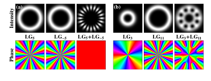
The maximum intensity of a single LGℓ beam can be approximated to at a radius Turnbull and this approximation improves for large . One can also show that the electric field in the radial direction has a full-width-half-maximum (FWHM) of . By choosing (i.e. with , and the two LG electric fields have similar maximum amplitudes and are separated by 1 FWHM. This leads to a dark lattice with an approximately uniform depth in the radial and azimuthal directions (Fig. 1(b)). We also note that the intensity gradient becomes maximal at which can be used for determining lattice site stability at high rotation rates.
II Rotating ring lattice experiment
Precise laser frequency shifts can be produced by passing light through an acousto-optic modulator (AOM). An acoustic modulation of angular frequency applied to a crystal produces a traveling Bragg grating, shifting the frequency of the first order diffracted beam by . Typically operating at around MHz, such modulators can be tuned over ’s of MHz. Two AOMs operating at and can produce light beams differing in angular frequency by which can range from 0 to 10’s of MHz. Our radio frequency signal generators (Marconi 2019) are passively highly stable, but to ensure long term relative stability we synchronize their MHz clocks. In order to eliminate the slight angular shift produced by tuning the modulator frequency, the experiment is configured in a double-pass arrangement, thus doubling the frequency shift to . We note that alternatively, a small frequency shift can be imposed onto a light beam by passing circularly polarized light through a rotating half wave plate Garetz , which due to an accumulated geometric or Berry phase Simon , shifts the frequency by twice the rotation speed of the waveplate. This approach has been employed in optical tweezers Paterson .
A Gaussian laser beam can be readily converted into a Laguerre-Gaussian mode by diffraction from a forked grating where the positive and negative first order beams correspond to opposite signs of Bazhenov . In our experiment the forked gratings are generated on a computer addressed SLM (HoloEye). The mode purity of the diffracted Laguerre-Gaussian beams is enhanced beyond standard hologram design by incorporating a spatially dependent modulation of the hologram blazing Leach .
Figure 2 shows the experimental arrangement used to create bright and dark rotating ring lattices.
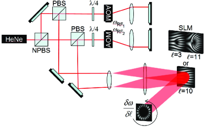
The Gaussian beam from a helium-neon laser is divided and double passed through two AOMs, leading to laser beams with an angular frequency difference of . These beams are expanded to the size of the SLM. For the bright lattice, the SLM is programmed with an -forked diffraction grating and the two beams are aligned such that the positive and negative diffracted first-order, which have opposite signs of , subsequently interfere to give an intensity pattern rotating at angular frequency .
For the dark lattice we need to overlap two appropriate Laguerre beams with order and . In our experiment we generated the required and forked holograms on different parts of the same SLM, with each laser beam incident on one of the areas and aligned so that the reflected beams are recombined to form the petalled dark lattice. We note that alignment of the and beams is comparatively uncritical as the true zero intensity at the dark lattice sites results from optical vortices (a electric field phase winding around the dark lattice site).
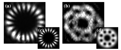
Visualization of a rotating lattice requires high speed photography. Using shutter speeds down to ns we have observed the rotating intensity patterns for frequency shifts of up to ’s of MHz between the two interfering Laguerre-Gaussian modes. The petal patterns rotate at the expected frequencies. In Fig. 3(a) and (b) we show still images of the light and dark lattice respectively, which agree well with theory.
III Applications to atom optics
By subjecting cold atoms to the dark or bright ring lattice described above, they can be trapped in the resulting light potential. In order to limit losses due to photon scattering we assume a light beam far detuned from the atomic resonance. The AC Stark potential , and photon scattering rate are related to the light intensity , and detuning by:
| (3) |
where and denote the linewidth and saturation intensity of the atomic transition, respectively. To illustrate the experimental feasibility of our scheme we use the two-level dipole potential approximation, this could be extended to a higher-order multi-level atom model approx . We now consider the specific example of the D2 transition of 87Rb atoms with W m-2. We assume a ring lattice laser total power of W, which is focussed to a beam waist of m at nm for trapping in the bright lattice and nm for trapping in the dark lattice. For a ring lattice with 10 potential wells this results in a peak intensity of W m2 corresponding to a potential well K deep for the bright () lattice and W m2 corresponding to K for the dark lattices respectively. The coldest atoms trapped in the high intensity regions of the red detuned light potential will scatter a photon every s. For the blue detuned lattice the coldest atoms are trapped at dark lattice sites and scattering will be negligible – even the hottest atoms only scatter a photon every s.
The optical lattice potential is sufficient to provide confinement in the transverse direction. To additionally localise atoms in the axial direction we suggest a hybrid trap, combining the optical lattice with a quadrupole magnetic trap kettoptplug ; ram . For the red lattice one could consider all-optical confinement in a tightly focused lattice with a short Rayleigh range, but there is a trade-off between axial confinement and scattering rate. Instead, atoms could be optically pumped into magnetic weak-field-seeking states and loaded into a quadrupole magnetic potential . The centre of the quadrupole field could be positioned away from the beam focus to ensure a stable Gouy phase. However, for a standard quadrupole gradient of G/cm, the atoms will be confined axially to a region much smaller than the Rayleigh range and the twist of the Gouy phase becomes negligible. In this hybrid magnetic and optical trap one can use standard RF evaporation, allowing in-situ cooling to quantum degeneracy. Circularly polarised LG lattice beams are required to maintain the symmetry between the quadrupole magnetic field and the light field and obtain a uniform ring lattice potential.
Alternatively, one can provide axial confinement in a ring lattice by using counterpropagating laser beams to create a standing wave, generating an axially separated stack of lattices similar to the method suggested in Amico . However, by introducing a frequency shift between the forward and backwards LG beam, the individual ring lattices will not only rotate but also translate along the -axis at a speed . Additionally, having a single ring lattice rather than a stack of ring lattices simplifies the experiment and enables single-site addressability.
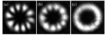
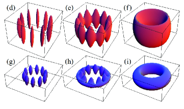
Our hybrid ring lattice enables the observation of the Mott insulator transition in a geometry with periodic boundary conditions. To adjust the barrier depth, and hence the tunneling between sites, the relative power in the beams can be varied. Experimentally, this can easily be achieved by varying the modulation amplitude of both AOMs while keeping the overall light intensity constant. To make full use of all laser power, an electro-optic modulator could be used to rotate the polarisation from the laser incident on a polarising beamsplitter leading to the two AOMs. For the bright lattice variation directly converts a uniform ring into a ring lattice. Images from our optical experiment are shown in Fig. 4(a)-(c) and the corresponding hybrid lattice theory in Fig. 4(d)-(f). For the dark lattice, the transition between uniform and multi-petalled ring is achieved by gradually dimming the outer LG beam, and outer transverse confinement is then provided by the magnetic potential (Fig. 4(g)-(i)).
The dynamic nature of our lattice could also be used to initiate persistent currents. In order to trap atoms in a rotating well pattern, several conditions need to be fulfilled: their initial temperature must be low enough in order to be trapped, the rotation speed must change slowly enough so that the atoms can adiabatically follow, and the centrifugal acceleration must be small enough for the radial potential gradient. This constraint is much higher than the critical rotation rate for vortex creation in 1D rad/s for our parameters.
IV Conclusions
We have experimentally obtained both bright and dark optical ring lattices, with tunable barriers between sites, and with a tunable rotation rate. Furthermore we have shown that, in combination with a magnetic trap, these lattices will be ideal for studying quantum degenerate gases. Future applications of the lattice include studies of: persistent currents, rotation of a “quantum register,” collisional studies using two counter-propagating rings.
Acknowledgements: This work is supported by the UK EPSRC, and SFA is a Dorothy Hodgkin Research Fellow of the Royal Society. VEL and DE were supported by ‘Pythagoras II’ of the EPEAEK programme and VEL was also supported by the CATS programme of the ESF (grant 756).
References
- (1) P. S. Jessen and I. H. Deutsch, Adv. At. Mol. Opt. Phys. 37, 95 (1996).
- (2) M. Greiner et al., Nature 415, 39 (2002).
- (3) F. S. Cataliotti et al., Science 293, 843 (2001).
- (4) L. Fallani et al., Phys. Rev. Lett. 91, 240405 (2003).
- (5) D. S. Naik, S. R. Muniz and C. Raman, Phys. Rev. A 72, 051606(R) (2005);
- (6) S. Gupta et al., Phys. Rev. Lett. 95, 143201 (2005); A. S. Arnold, C. S. Garvie and E. Riis, Phys. Rev. A 73, 041606(R) (2006).
- (7) L. Amico, A. Osterloh and F. Cataliotti, Phys. Rev. Lett. 95, 063201 (2005).
- (8) C. S. Adams and E. Riis, Prog. Quant. Electr. 21, 1 (1997); E. A. Hinds and I. G. Hughes, J. Phys. D 32, R119 (1999).
- (9) S. Kuhr et al., Science 293, 278 (2001).
- (10) J. E. Curtis, B. A. Koss and D. G. Grier, Opt. Commun. 207, 169 (2002).
- (11) G. Sinclair et al., Opt. Express 12, 5475 (2004).
- (12) S. Bergamini et al., J. Opt. Soc. Am. B 21, 1889 (2004).
- (13) V. Boyer et al., Phys. Rev. A 73, 031402(R) (2006).
- (14) J. Courtial, D. A. Robertson, K. Dholakia, L. Allen and M. J. Padgett, Phys. Rev. Lett. 81, 4828 (1998).
- (15) M. Harris, C. A. Hill and J. M. Vaughan, Opt. Commun. 106, 161 (1994).
- (16) M. J. Padgett and L. Allen, Opt. Commun. 121, 36 (1995).
- (17) B. A. Garetz and S. Arnold, Opt. Commun. 31, 1 (1979).
- (18) R. Simon, H. J. Kimble, and E. C. G. Sundarshan, Phys. Rev. Lett. 61, 19 (1988).
- (19) J. Arlt et al., Opt. Express 10, 844 (2002).
- (20) V. Yu. Bazhenov, M. V. Vasnetsov and M. S. Soskin, JETP Lett. 52, 429 (1990).
- (21) J. Leach, M. Dennis, J. Courtial and M. Padgett, Nature 432, 165 (2004).
- (22) C. S. Adams et al., J. Phys. B 36, 1933 (2003); V. E. Lembessis and D. Ellinas, J. Opt. B 7, 319 (2005).
- (23) K. B. Davis et al., Phys. Rev. Lett. 75, 3969 (1995).