Also at ]Institute for Integrated Energy Systems, University of Victoria, P.O. Box 3055, Victoria, BC V8W 3P6, Canada
Effect of transient pinning on stability of drops sitting on an inclined plane
Abstract
We report on new instabilities of the quasi-static equilibrium of water drops pinned by a hydrophobic inclined substrate. The contact line of a statically pinned drop exhibits three transitions of partial depinning: depinning of the advancing and receding parts of the contact line and depinning of the entire contact line leading to the drop’s translational motion. We find a region of parameters where the classical Macdougall-Ockrent-Frenkel approach fails to estimate the critical volume of the statically pinned inclined drop.
pacs:
????I Introduction
Dispense a drop on a flat substrate and then tilt it. Depending on the balance between gravitational and capillary pinning forces, the drop will slide down or stay at rest. Raindrops sticking or sliding on a vehicle windshield provide a familiar example of this drop stability problem, which is of broad practical importance.
In structural genomics, for example, protein crystals are grown by dispensing protein-containing drops onto horizontal glass or plastic substrates. Because protein crystals are extremely fragile, the substrate is then inverted so as to prevent any nucleating crystals from sedimenting onto and adhering to it Hampton ; McPherson . Crystals in these ”hanging drops” instead sediment to the liquid-air interface, where they can be easily extracted without damage. It was shown previously Berejnov that pinning conditions are important for maintaining stability of the inclined drops of protein solutions with concentration suitable for crystallization. Obviously, crystal nucleation and growth - and thus the ultimate quality of the molecular structure determined by X-ray crystallography - are strongly affected by the drop shape and consequently by the drop stability. Drop shape variations are also a major obstacle to automated optical recognition of the protein drop’s contents, important in high-throughput experiments. More generally, the motion of contact lines is related to motion of elastic manifolds in the presence of disorder Fisher , including motion of interfaces in porous media and depinning of flux line lattices Blatter , Wigner crystals and charge-density waves Thorne .
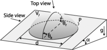
The pinning of an inclined drop that prevents its continuous motion is related to the contact angle hysteresis, whose magnitude is usually estimated from the maximum difference between the contact angles and at the advancing (downhill) and receding (uphill) edges of the contact line, as shown in Fig. 1. If this maximum difference is nonzero, then drops of volume less than a critical may remain at rest at a given inclination angle Frenkel ; Macdougall , although this is a necessary but not sufficient condition for drop stability. A simple formula
| (1) |
was obtained by Macdougall and Ockrent as a phenomenological explanation of their experiments with the inclined drops Macdougall and independently by Frenkel as a boundary condition of one exactly formulated problem of the drop stability on a tilted surface Frenkel . Here is an appropriately scaled material constant, is the capillary length, and , , , and are the density, surface tension, gravity, and drop width, respectively.
The MOF formula Eq. (1) is believed to describe the relation between contact angle hysteresis and the equilibrium and criticality of an inclined dropFrenkel ; Macdougall ; Aron ; Bikerman ; Kawasaki ; Furmidge ; Extrand ; Roura , from small inclinations and volumes at which the drop deforms but remains static up to the critical inclination or volume at which it begins to slide continuously. The validity of the MOF functional form has been verified in a variety of experiments Macdougall ; Aron ; Bikerman ; Kawasaki ; Furmidge ; Extrand ; Roura . However, surprisely it was noted that all phenomenological improvements have led to the same general form of Eq. (1), with different length factors instead of and this formula has not always correctly predicted the exact volumes of drops pinned at critical conditions.
Despite extensive study, the problem of the stability of a one-component drop on an inclined surface has yet to be addressed in its full richness. Here we examine the equilibrium and criticality of a water drop pinned on a hydrophobic flat glass slide. In particular, we examine a wide range of quasi-static tilting for a moderately hydrophobic surface ( contact angle) having a moderate range of contact angle differences . We show that the MOF criterion is not general and its limitation is based on the existence of transient modes of displacement, whose mechanics have not yet been described. We have clearly resolved the partial and global instabilities of the contact line. Three coexistence curves corresponding to the partial depinning of the advancing and receding parts of the contact line and to depinning and continuous motion of the entire contact line mark those instabilities unambiguously. The transient displacements of the advancing and receding parts of the contact line have different scalings. We find that the difference between the drop’s maximum and minimum contact angles cannot reliably be used to predict the maximum pinning strength and the onset of drop sliding.
II Contact line stability and depinning for an inclined drop
A drop’s contact line, between its initially static pinned state and its steady sliding motion, may exhibit a continuous series of intermediate states. This fact has been previously noted Bikerman ; Furmidge ; Extrand ; Extrand2 , but its effect on the stability of an inclined drop has not been fully appreciated.
After being dispensed on a homogeneous, flat, horizontal substrate, a drop will have a circular contact line. As the substrate angle is slowly stepped upward, a drop of volume eventually becomes unstable and slides continuously down the substrate. At a smaller angle, the drop’s contact line may become locally unstable, and undergo local displacements that change the contact line’s shape but that do not produce continuous motion. Although these critical angles for the onset of global and local instability are in general different, for some experimental conditions they may be weakly distinguishable in measurements. In this case, the transient pinning of the contact line does not affect drop criticality and may be neglected. The drop equilibrium and criticality may then be described in terms of a simple energetic balance, as in the MOF formula, between the potential and capillary energies of the inclined drop. When the global and local equilibriums are well separated, the contact line can be displaced over the substrate while simultaneously maintaining its stability against continuous sliding. In this case, because the contact line configuration corresponding to the global equilibrium is unknown, the simple energetic balance describing the drop stability criterion should be reconsidered.
Several attempts to analytically describe the shape, reconfigurations and criticality of the contact line for an inclined drop have been reported. In 1948, using a variational technique to analyze the drop shape for small inclinations, Frenkel Frenkel explicitly showed for a 2D inclined drop that equilibrium conditions and translational drop instability lead to the MOF criteria Eq. (1). Popova Popova extended the variational technique to a 3D drop at small inclination. She analytically calculated the equilibrium drop shape, contact line shape, and the contact angle as a function of position along the contact line. Carre and Shanahan CareeShanahan used the ideas similar to Popova’s variation of the contact angle along the contact line to calculate the pinning force, and obtained a criticality equation similar to the MOF criterion Eq. (1). Dussan Dussan , stimulated by earlier experiments Bikerman ; Furmidge , studied criticality of 3D inclined drops with an initially elliptically-like contact line. Using the equations of continuous fluid dynamics, she found an equation of equilibrium states for the inclined drop for small hysteresis, which can be used for obtaining the critical conditions of the inclined drops also. Popov Popov used a variational analysis to examine the equilibrium and criticality of a weakly perturbed hemi-spherical drop at large inclinations. His solution describes well only the stability of small drops inclined near .
It is important to note that in all the above studies Frenkel ; Popova ; CareeShanahan ; Dussan ; Popov , the contact line shape was either assumed arbitrarily or else determined from the minimum of some free energy. Furthermore, in all cases the chosen contact line shape was assumed to be maintained up to and including the critical point for the onset of instability and drop sliding. Consequently, these approaches ignored the transitional behavior of the contact line prior to global criticality.
In addition to these analytic attempts, two numerical studies Dimitrakop ; Iliev

have explored freely displacing contact lines. Dimitrakopoulos and Higdon Dimitrakop reported transient contact line behavior similar to that observed here. However, the implementation of pinning in the numerical algorithm, which leads to the experimental-like contact line profiles, was arbitrary, and their -constrained boundary conditions need further clarification and justification. Iliev Iliev used two phenomenological parameters to describe the pinning. However, the unclear connection between those parameters and experiment and the absence of numerically calculated the drop deformations and criticality curves make comparison with the present results difficult.
III Material and experimental methods
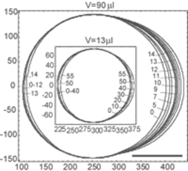
Distilled and deionized water purified by a NANOpure II system (Barnstead, Boston, MA) was dispensed onto siliconized flat glass slides with diameter 22 mm (HR3-231, Hampton Research, Laguna Niguel, CA). On a freshly unpackaged slide, a 40 water drop formed a reproducible contact angle of . To determine drop stability on a given slide, a drop was manually dispensed onto a horizontal slide using a 100 micropipette (Pipetman Co., France). The slide was then slowly rotated in steps on a home-built rotation stage. The time interval between rotations was roughly one minute, long enough to allow transient shape relaxations to dissipate. A 640x480 pixel resolution digital camera (Cohu, San Diego, CA) with a telecentric 55 mm objective (Computar, Japan) was mounted on the rotation stage. Image recording at six frames per second began immediately after each stage rotation was completed and continued throughout the entire relaxation period. A custom image recognition program was written and implemented in LabView to process each image to extract the contact line. Fig. 2 shows examples of contact line profiles at different tilt angles determined in this way.
The apparent contact angles at the advancing and receding contact lines were measured from the drop side view using an independent horizontal goniometer. Dispensed drop volumes were accurate to , and tilt and contact angle measurements were accurate to . Measured velocities of average drop contact line motion of the transient displacements were mm/s. Using water’s dynamic viscosity g/(cm s) and surface tension dyn/cm yields an upper bound for the capillary number . Thus all dynamic effects during contact line rearrangement can be neglected.
On a horizontal, homogeneous flat surface, a drop’s minimum free-energy configuration has a circular contact line. In practice, the actual contact line shape depends on the initial contact conditions formed while the drop is dispensed. We found that the subsequent contact line displacements depend on the contact line’s initial shape and on the initial contact angles along it. Consequently, we carefully prepared and selected drops with initially circular contact lines.
IV Results
Fig. 2 shows typical results for the contact line position recorded at different tilt angles, for two drops with volumes of 13 and 90 , respectively. As the substrate is tilted, the contact line remains pinned in its original circular configuration. Beyond a first critical tilt angle , the advancing portion of the contact line becomes locally unstable and displaces in an attempt to find a new equilibrium, eventually reaching a new static configuration. Beyond a second, larger critical angle , the receding part of the contact line becomes locally unstable and displaces, but the drop again finds a new static configuration. Beyond a third critical angle of inclination , the drop becomes unstable and slides continuously. The difference in the behavior of the advancing and receding contact lines implies that pinning along the contact line is not homogeneous. This conclusion is consistent with previous calculations and measurements Finn ; Brown ; CareeShanahan ; ElSherbini of the contact angles along a contact line’s circumference.
Fig. 3 examines how the displaced length of the static contact line evolves with respect to the critical parameters and . The total displaced length of the contact line at the advancing and receding edges following a tilt increment to angle can be determined by subtracting images acquired at from those at that angle .

For small such that the contact line remains circular, the resultant images still show some displaced pixels that are randomly distributed over the contact line, arising from noise and other measurement errors. In Fig. 3 (a) and (b), this regime corresponds to the horizontal ”zero” parts of the curves. At larger (beyond or ), the advancing or receding part of the contact line begins to displace (Fig. 3 insets), and the difference image shows a chain of connected pixels. This chain grows on further inclination to form a displacing front of length .
Fig. 3 shows the ratio of the total displaced length to the unperturbed drop perimeter (at ) versus , where corresponds to onset of drop instability and continuous translational motion. Fig. 3 visualizes unambiguously the fact noted previously Bikerman ; Furmidge ; Extrand ; Extrand2 that the advancing contact line may displace at a lower inclination angle than the receding contact line. Although there is considerable scatter in the data, there is still remarkable consistency in behavior over the factor-of-10 volume range examined. The advancing contact line begins moving at a small and the displaced length grows monotonically, reaching a consistent value of just before . In contrast, the receding contact line remains pinned until , and then steeply increases to at . Note that, because the drop becomes distended, the total contact line length near exceeds its initial length .
Fig. 4 presents a subset of the data in Fig. 2, plotted in the space of critical parameters and . The solid and open squares indicate the onset of local instability at the advancing and receding parts of the contact lines, respectively, and the solid triangles indicate the onset of continuous drop motion. A log-log scaling of this data is presented in Fig. 5, and clarifies the observed differences in the transient displacements of the contact lines.

Between absolute stability (zone (a)) - where the initial circular contact line is maintained at all inclinations - and continuous motion (zone (e)), the contact line passes through three transitions: instability of the advancing line at (Fig. 4, curve ), instability of the receding line at (Fig. 4, curve ), and finally, instability at leading to continuous translational motion of the entire contact line (curve ). Fig. 5 also clearly shows that there are five zones of behavior in the space in which the contact line loses its stability. In addition to zones (a) and (e), in zone (b) the contact line is stable only up to a maximum inclination . In zone (c), between the and transition curves, the contact line shows partial instability at its advancing edge. In zone (d) both the advancing and receding portions participate in quasi-static displacements, but the drop still remains at rest.
It is interesting to note the functional dependencies of the transitional curves. The receding contact line transition and the transition to continuous sliding have the same volume scaling . However, the advancing transition scales as . This suggests that the advancing instability is controlled by disturbances that do not scale like the drop size. The length factor in the MOF formula for the advancing part of the contact line should thus be replaced by some new scaling , which is independent of the drop size and is likely related to the length scale of local perturbations.

Fig. 6 shows the measured apparent advancing and receding contact angles versus inclination angle, for drop volumes ranging over a factor of 8. The measurements were performed for each particular drop volume at inclinations below , for which the contact line reached a static configuration after each inclination increment. Solid guide lines denote the stable regions ((a) and (b) in Fig. 5), and dashed lines indicate zones of partial instability at the advancing and receding edges ((c) and (d) in Fig. 5). The drop contact line traverses the stable zones (a) and (b), passes the advancing and receding displacement transitions and the zones of partial instability (c) and (d), and eventually reaches the absolutely unstable zone (e). These data deviate significantly from those presented in Ref. Wolfram , where a hydrophobic substrate was also used. In particular, while the advancing angle in Fig. 6 is nearly independent of drop volume, the receding angle depends strongly on drop volume.
Fig. 6 raises another interesting question, touched on in Krasov : which values of the advancing and receding contact angles and for a given drop volume do we have to choose for an adequate description of contact line pinning and stability? According to Fig. 5 and Fig. 6, the advancing and receding angles often lie in different zones of stability in Fig. 5. In particular, the last absolutely stable of (indicated in Fig. 6 by the points at which the solid curves connect to the dashed ones) do not have corresponding absolutely stable values of ; the advancing line has undergone quasi-static displacements that modify (reduce) from what would be obtained if the advancing line had remained in its initial position. In this case when the angles lie in different zones of stability, they cannot be simply inserted into the MOF formula to get an accurate measure of pinning strength and drop stability. Traditionally, the contact angle hysteresis at criticality is obtained from the difference measured at the last inclination before the drop begins to slide. These correspond to the last points on the dashed curves in Fig. 6, and to the - transition curve in Fig. 4 and Fig. 5.
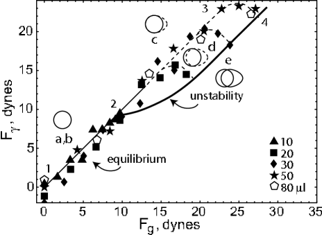
Fig. 7 shows a direct test of the MOF equation as a predictor of the equilibrium and stability of inclined drops. Using the perimeters from images similar to those presented in Fig. 2 and the traditional choice for the contact angles and to quantify the contact angle difference, we may rescale the data of Fig. 4 and Fig. 6 using and such that the MOF fit of Eq. (1) appears as a straight line. At small values of the scaled variables, the data are in fact linear, and a fit gives dynes/cm, consistent with the accepted value for water at T=22 C of 72.5 dynes/cm. The part 1-2 of the solid line corresponds to the regions (a) and (b) in Fig. 5, where the contact line of pinned drops is in equilibrium and does not change its initial configuration (see an insert corresponding to (a, b)-region in Fig. 7). Thus, the MOF approach is able to describe well deformation of a meniscus upon the drop inclination while the contact line remains completely pinned and the gravity and capillarity forces can balance each another. This behavior in this region of parameter space has been observed in many previous studies Macdougall ; Bikerman ; Kawasaki ; Furmidge ; Extrand ; Roura .
After the point 2 at larger and , corresponding to larger inclinations or drop volumes or contact angle differences , the equilibrium curves deviate substantially from the linear fit: line 2-3 (dashed curves in Fig. 7). The line 2-3 corresponds to the region (c) in Fig. 5 where the advancing part of the contact line is not stable and exhibits quasi-static displacements (see an insert corresponding to the region (c) in Fig. 7). The points at largest - on the ”hooks” of the dashed curves in Fig. 7 - represent the last stable contact line configurations, corresponding to the -line in Fig. 5. The zone between the curves 2-3 and 2-4 corresponds to the (d) region of Fig. 5. According to Fig. 5, in this zone both the advancing and receding contact lines are unstable but only undergo quasi-static displacements (not sliding). These last points form the criticality curve 2-4, which obviously, cannot be described by the MOF formula.
V Conclusions
The present experiments show that the standard picture of instability of inclined drops is over-simplified, and that the behavior is more complex than assumed in previous analytical treatments. In particular, the assumption that the contact line remains unchanged with inclination until it begins to slide does not adequately describe the actual depinning.
As the substrate tilt is increased, three distinct depinning transitions - of the advancing portion of the contact line, the receding portion of the contact line, and of the contact line as a whole - are observed. These transitions have different effects on overall drop stability. Transient displacements of the advancing contact line in zone (c) decrease drop stability locally (-curve in Fig. 4). But on further inclination, in zone (d), transient displacements of the receding contact line (occurring with additional advancing displacements) involve whole contact line in reconfiguration that stabilizes the overall pinning (-curve in Fig. 4 and the ”hooks” in Fig. 7). We understand this stabilizing effect as arising a new mechanism of dissipation directed against the drop sliding, which origin is based on pinning-depinning of the local parts of the drop contact line.
Consistent with the MOF formula, the contact angle difference varies linearly with up to inclinations at which the receding contact line displaces. But the MOF formula fails to describe drop stability at larger angles and the critical transition to drop sliding.
Acknowledgements.
This work was supported by the NIH (R01 GM65981-01). We thank C. W. Extrand for helpful and stimulating e-mail discussion and P. Dimitrakopoulos and M. H. Murray for critical reading of our manuscript.References
- (1) Hampton Research, in Crystallization Research Tools, 13, 2003, Laguna Niguel, CA. Hampton Research.
- (2) A. McPherson, Crystallization of Biological Macromolecules (Cold Spring Harbor Laboratory Press, New York, 1999).
- (3) V. Berejnov and R.E. Thorne, Acta Cryst. D 61, 1563-1567 (2005). http://lanl.arxiv.org/abs/cond-mat/0604326
- (4) D. S. Fisher, Physics Reports, 301, 113 (1998).
- (5) G. Blatter et al., Rev. Mod. Phys. 66, 1125 (1994).
- (6) R. E. Thorne, Physics Today, 49, 42 (1996).
- (7) Y. I. Frenkel, J. Exp. Theor. Phys., russ. 18(7), 659-667 (1948). This work, to date available only in Russian, has not been adequately appreciated, so we have made a translation available at http://xxx.lanl.gov/abs/physics/0503051
- (8) Y. B. Aron and Y. I. Frenkel, J. Exp. Theor. Phys., russ. 19(9), 807-813 (1949).
- (9) G. Macdougall and C. Ockrent, Proc. R. Soc. London, 180(A981), 0151-0173 (1942).
- (10) J.J. Bikerman, J. Colloid Science, 5(4), 349-359 (1950).
- (11) C.G. Furmidge, J. Colloid Science, 17(4), 309 (1962).
- (12) R.A. Brown, F.M. Orr Jr., L.E. Scriven, J. Colloid and Interface Science, 73, 76 (1980).
- (13) A.I. ElSherbini and A.M. Jacobi, J. Colloid and Interface Science, 273, 556-565 (2004).
- (14) R. Finn, Equilibrium Capillary Surfaces, Springer-Verlag, New York, 1986.
- (15) L. N. Popova, Fluid Dynamics, 18(1), 634-637 (1983).
- (16) A. Carre, and M. E. R. Shanahan, J. Adhesion, 49, 177-185 (1995).
- (17) K. Kawasaki, J. Colloid Science, 15, 402-407 (1960).
- (18) C. W. Extrand and Y. Kumagai, J. Colloid and Interface Science, 170, 515-521 (1995).
- (19) P. Roura and J. Fort, Phys. Rev. E, 64, 011601 (2001).
- (20) C. W. Extrand and A. N. Gent, J. Colloid and Interface Science, 138(2), 431-442 (1990).
- (21) E. B. Dussan, J. Fluid Mech., 151, 1-20 (1985).
- (22) V. G. Popov, High Temperature, 28(5), 731-736 (1990).
- (23) A. Lawal and R.A. Brown, J. Colloid and Interface Science, 89(2), 332-345 and 346-352, (1982).
- (24) S. D. Iliev, J. Colloid and Interface Science, 194(2), 287-300 (1997).
- (25) P. Dimitrakopoulos and J.J.L. Higdon, J. Fluid Mech. 395, 181-209 (1999).
- (26) E. Wolfram and R. Faust, in Wetting, Spreading and Adhesion, edited by J. F. Padday (Academic Press, New York, 1978), p. 213-222.
- (27) B. Krasovitski and A. Marmur, Langmuir, 21, 3881-3885 (2005).