Design of resonant microcavities: application to optical gyroscopes
Satoshi Sunada and Takahisa Harayama
Department of Nonlinear Science, ATR Wave Engineering Laboratories, 2-2-2 Hikaridai Seika-cho Soraku-gun, Kyoto, 619-0228 Japan
sunada@atr.jp
Abstract
We study theoretically and numerically the effect of rotation on resonant frequencies of microcavities in a rotating frame of reference. Cavity rotation causes the shifts of the resonant frequencies proportional to the rotation rate if it is larger than a certain value. Below the value, a region of rotation rate exists where there is no resulting the frequency shifts proportional to the rotation rate. We show that designing cavity symmetry as () can eliminate this region.
OCIS codes: (140.4780) Optical resonators, (140.3410) Laser resonators, (140.3370) Laser gyroscopes, (350.5720) Relativity.
References and links
- [1] E. J. Post, “Sagnac effect,” Rev. Mod. Phys. 39, 475-493 (1967).
- [2] W. W. Chow, J. Gea-Banacloche, L. M. Pedrotti, V. E. Sanders, W. Schleich, and M. O. Scully, “The ring laser gyro,” Rev. Mod. Phys. 57, 61-104 (1985).
- [3] F. Aronowitz, in Laser Applications, M. Ross, ed. (Academic, New York, 1971), Vol. 1, pp 133-200.
- [4] L. N. Menegozzi and W. E. Lamb, Jr., “Theory of a ring laser,” Phys. Rev. A 8, 2103-2125 (1971).
- [5] A. Kuriyagawa and S. Mori, “Ring laser and ring interferometer in accelerated systems,” Phys. Rev. D 20, 1290-1293 (1979).
- [6] H. J. Arditty and H. C. Lefevre, “Sagnac effect in fiber gyroscopes,” Opt. Lett. 6, 401-403 (1981).
- [7] W. M. Macek and D. T. M. Davis, “Rotation rate sensing with traveling-wave ring lasers,” Appl. Phys. Lett. 2, 67-68 (1963).
- [8] J. L. Anderson and J. W. Ryon, “Electromagnetic radiation in accelerated systems,” Phys. Rev. 181, 1765-1774 (1969).
- [9] E. Landau and E. Lifshits, The Classical Theory of Fields (Butterworth-Heinemann. Oxford, 1975).
- [10] C. V. Heer, “Resonant frequencies of an electromagnetic cavity in an accelerated system of reference,” Phys. Rev. 134, A799-804 (1964).
- [11] Y. Yamamoto and R. E. Slusher, “Optical processes in microcavities,” Phys. Today 46, 66-73 (1993).
- [12] R. K. Chang and A. J. Campillo, eds., Optical processes in microcavities (World Scientific Publishing, Singapore, New Jersey, Hong Kong, 1996).
- [13] S. Sunada and T. Harayama, “Sagnac effect in resonant microcavities,” Phys. Rev. A 74, 021801(R) (2006); T. Harayama, S. Sunada, and T. Miyasaka, “Wave chaos in rotating optical cavities,” Phys. Rev. E 76, 016212 (2007).
- [14] Equation (7) agrees with a conventional expression for frequency difference: by applying assumptions (i) and (ii) to Eq. (7). In the above, is the area bounded by the optical path, is the perimeter of the optical path, and is the eigen frequency of the non-rotating ring cavity approximated as .
- [15] Here, CW- (CCW-) rotating waves mean those having mostly negative (positive) angular momentum components, as in the definition of Eq. (23) in Ref. [13].
- [16] R. J. C. Spreeuw, R. Centeno Neelen, N. J. van Druten, E. R. Eliel, and J. P. Woerdman, “Mode coupling in a He-Ne ring laser with backscattering,” Phys. Rev. A 42, 4315-4324 (1990).
- [17] G. Hackenbroich, E. Narimanov, and A. D. Stone, “Quantum perturbation theory for the level splitting in billiards,” Phys. Rev. E 57, R5-R8 (1998).
- [18] M. Choi, T. Fukushima, and T. Harayama, “Alternative osicillation with difference in quasi-stadium laser diodes,” in CLEO/Pacific Rim 2007, WGI-3 (2007).
- [19] Morton Hamermesh, Group Theory and Its Application to Physical Problems, (Dover New York, 1989).
- [20] S. Sakanaka, ”Classification of eigenmodes in rf-cavities using the group theory,” Phys. Rev. ST Accel. Beams 8, 072002 (2005).
- [21] M. Sorel, P. J. Laybourn, G. Giuliani, and S. Donati, “Progress on the GaAlAs ring laser gyroscope,” Alta Frequenza, Rivista Di Electonica, 10 45-48, (1998); M. Sorel, G. Giuliani, A. Scire, R. Miglierina, S. Donati, and P. J. R. Laybourn, “Operating regimes of GaAs-AlGaAs semiconductor ring lasers: experiment and model,” IEEE J. Quantum Electron. 39, 1187-1195 (2003).
- [22] H. Cao, C. Liu, H. Ling, H. Deug, M. Benavidez, G. M. Peake, G. A. Smolyakov, P. G. Eliseev, and M. Osinski, “Frequency beating between monolithically integrated semiconductor ring lasers,” Appl. Phys. Lett. 86, 041101 (2005).
- [23] F. C. Rarnberg, R. Johnson, W. Ellerbusch, B. Schermer, and R. Gopinath, “Cavity element for resonant micro optical gyroscope,” IEEE Trans. Aerosp. Electron. Syst. 15, 33-36 (2000).
- [24] M. N. Armenise, V. M. N. Passaro, F. Leonardis, and M. Armenise, “ Modeling and design of a novel miniaturized integrated optical sensor for gyroscope systems,” J. Lightwave Technol. 19, 1476 (2001).
- [25] Ben Zion Steinberg, “Rotating photonic crystals: a medium for compact optical gyroscopes,” Phys. Rev. E 71, 056621, (2005).
1 Introduction
The propagation of light fields and the resonances of optical cavities in rotating systems have been experimentally and theoretically studied as one of the most basic and interesting problems of electromagnetics in arbitrary accelerated systems [1]. Many of these investigations have concentrated on rotating ring interferometers and rotating ring cavities because such devices can be applied to optical rotation velocity sensors [1, 2, 3, 4, 5, 6].
One of the first suggestions to optically detect rotation rate was given by Sagnac in 1913 [1]. The basic idea is to use the difference in one round-trip time between clockwise (CW-) and counter-clockwise (CCW-) propagating waves due to rotation in a ring interferometer. The time difference was experimentally observed as phase difference. Today the measurement of phase difference in ring interferometers has become very precise due to optical fiber technology.
On the other hand, rotation also affects the resonances of optical cavities (modal structures). The degenerate resonant frequency of a non-rotating ring cavity was split into a doublet by rotation, and the fact was confirmed by the experiments of Macek and Davis [7]. The effect of the splitting has becomes the basic principle of the operation of ring laser gyroscopes, which are now used in airplanes, rockets, and ships etc. for autonomous navigation because they are the most precise sensors among any other types of gyroscopes.
So far, the effect of rotation on resonances (i.e., frequency splitting induced by rotation) has been explained as that which originated in the time difference between counter-propagating lights due to rotation. This fact has been derived by a kinematical approach (ray-optics) [1, 2, 3, 4, 5] or by a wave dynamical approach based on the electromagnetic equations of a naturally covariant form (or general theory of relativity) [1, 8, 9, 10]. For such theoretical approaches, the following assumptions are explicitly or implicitly used in their derivations: (i) The light field one-dimensionally propagates in slender waveguides such as optical fibers or ring cavities composed of more than three mirrors; (ii) The wavelength of the light is much shorter than the sizes of the cavities, i.e., The geometrical optics approximation is valid enough. The use of assumptions (i) and (ii) means that resonant modes can be expressed as CW- or CCW- propagating wave modes along a ring trajectory with identical resonant frequencies(i.e., degenerate states) in non-rotating cavities.
Recently, advanced semiconductor technologies make it possible to fabricate arbitrary-sized optical cavities [11, 12]. When the cavity size becomes smaller, however, it remains unclear whether assumptions (i) and (ii) are still valid and conventional theory based on them really works. In addition, resonant modes cannot always be expressed as counter-propagating waves in microcavities.
We have recently established a wave-dynamical approach to rotating resonant cavities without assumptions (i) and (ii). We showed that, when the angular velocity is larger than a certain value, the nearly-degenerate standing wave modes of a non-rotating microcavity change into a pair of counter-propagating wave modes and their frequency difference starts to increase proportionally to the angular velocity [13]. It has been revealed that, below the value of the angular velocity, a region exists where the frequency difference almost does not change, suggesting that the existence of this region might be an obstacle in the practical sense when one operates the microcavities as optical gyroscopes.
In this paper, we discuss the relation between the existence of this region and the symmetry of cavity shape and show that designing cavity symmetry as yields degenerate resonant frequencies and can eliminate the region.
This paper is organized as follows: In Sec. 2, we review the derivation for the shifts of resonant frequencies induced by rotation and the numerical results by a wave-dynamical approach without assumptions (i) and (ii). It is shown that there exists a region around zero angular velocity where the frequency shifts are almost not caused. Discussions are provided in Sec. 3, and we propose a method for eliminating the region in Sec. 4. Finally, a summary of this paper is provided in Sec. 5.
2 Theory
According to the electromagnetic equations of naturally covariant forms [8] or general theory of relativity [9, 10], electromagnetic fields in a rotating resonant microcavity are subject to the Maxwell equations generalized to a non-inertial frame of reference in uniform rotation with angular velocity vector . We derived the following stationary wave equation from the Maxwell equations by assuming that microcavities can be modeled as a waveguide, which is wide in the direction and thin in the direction [13]:
| (1) |
where . denotes coordinates in a rotating frame of reference with angular velocity vector . The cavity is at rest in the rotating frame of reference. and are respectively the velocity of the light and a refractive index inside the cavity, and is the wave number. We also assume that the TM or TE waves of the electromagnetic fields oscillate as . Below, we impose the Dirichlet boundary condition for simplicity, and resonant modes of rotating cavities can be obtained by solving Eq. (1) with two perturbation theories typically used in quantum mechanics.
First, we discuss a case where angular velocity is smaller than the following value :
| (2) |
where denotes the domain of the cavity, and is the spacing between adjacent eigenvalues of the wave number for Eq. (1) with , i.e., and are the wave functions of these eigenstates (resonant modes) that correspond to the adjacent eigenvalues. In this case, we apply the perturbation theory for non-degenerate states to Eq. (1) by assuming that, due to cavity rotation, the eigenvalue is shifted as and the wave function is changed as By substituting them to Eq. (1), we obtain
| (3) |
up to the first order of and , where
| (4) |
These results mean that, as long as angular velocity is small enough, frequency shift due to rotation does not occur, , and the wave functions of the eigenstates do not change CW- or CCW- rotating waves.
Next we discuss the case where angular velocity is larger than , i.e., . In this case, the perturbation theory used above breaks down because coefficient of resonant mode , which has the adjacent eigenvalue to , is no longer small due to . Instead, we use the perturbation theory for degenerate states. According to the perturbation theory, two nearly-degenerate wavefunctions and are superposed to reproduce the solutions of Eq. (1) as follows:
| (5) |
where the wavenumbers are shifted by rotation:
| (6) |
Accordingly, the frequency difference between the two eigenstates newly produced by cavity rotation is proportional to the angular velocity [14]:
| (7) |
where .
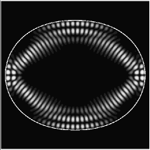
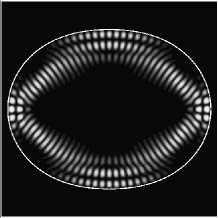
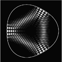
To demonstrate our theoretical results, we carry out the numerical simulation in a quadrupole cavity defined by boundary , where denotes the cylindrical coordinates. The parameters of the cavity are set as and the refractive index is , where there is a ring trajectory shown by the dashed line in Fig. 1. When the cavity is not rotated, solving Eq. (1) with yields the wavefunctions of the eigen modes corresponding to the ring trajectory, as shown in Figs. 2(a) and (b). As seen here, these modes are standing waves along the ring trajectory and have different parities with respect to the (horizontal and vertical) symmetry axes of the cavity. In addition, they have slightly different eigenvalues of the wavenumber; these modes are nearly-degenerate standing waves. We call the two modes shown in Figs. 2 (a) and (b) modes A and B, respectively.
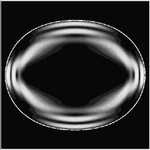
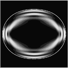
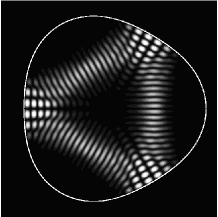
When the cavity is rotated but the angular velocity is smaller than (where ), the frequency difference between modes A and B does not increase, as shown in Fig. 3(a) , and the wavefunctions of modes A and B do not drastically change, and they remain standing waves. However, for , the frequency difference increases proportionally to the angular velocity . Then the wavefunctions of modes A and B are superimposed following Eq. (5) and change into the wavefunctions shown in Figs. 4(a) and (b), respectively. The wavefunctions corresponds to the CW- and CCW- rotating waves [15]. From these results, one can observe the Sagnac effect (in cases of resonant cavities) as the frequency difference between counter-propagating wave modes proportional to the angular velocity. Note that a region of angular velocity exists where the frequency difference almost does not change. This result can never be derived from the conventional theory of the Sagnac effect using assumptions (i) and (ii).

 |
 |
|---|---|
| (a) | (b) |

 |
 |
|---|---|
| (a) | (b) |
3 Discussion
Note that the existence of region is not akin to the so-called “lock-in” phenomenon that has been frequently observed in ring laser gyroscopes [2, 3, 4, 16]. The lock-in phenomenon in ring laser gyros is that CW- (CCW-) rotating wave modes are injection-locked to CCW-(CW-) propagating wave modes by backscatters in the ring lasers at a low rotation rate. However, in our analysis, the backscatters and the nonlinear effect of laser medium are not both taken into account. Our results show that a region of shown in the previous section exists even without backscatters and the nonlinearity of laser medium.
As seen in Eq. (2), the existence of region originates in the existence of non-degeneracy (or spacing ). It is well-known that spacing is determined by the ratio between the characteristic radius of cavity and wavelength of the light, (for example, Ref. [17]). Angular velocity increases as cavity size decreases. In such a case, the existence of the region might prevent the optical cavity from operating as an optical gyroscope, because the frequency difference almost does not change for angular velocity smaller than .
Recently, in a semiconductor microcavity laser called the quasi-stadium laser, the frequency difference between nearly-degenerate ring modes has experimentally measured as the frequency of oscillatory behavior, which the intensities of the CW- and CCW- output lights periodically oscillate with phase difference [18]. The frequency difference () was around 3 , although the value was changed by the pumping power. Applying Eq. (2) to the case of the quasi-stadium cavity, can be estimated as the order of , which is so large that one might not be able to experimentally observe frequency shift due to rotation even with any equipments. In the next section, we propose a method to remove the region.
4 Application: design of resonant microcavity gyroscopes
According to Eq. (2), one can see that equals zero in the case of
| (8) |
The simplest case that satisfies condition (8) is when a cavity has continuous symmetry, such as circular symmetry, (e.g., micro ring or microdisk) because there are degenerate CW- and CCW- rotating waves in the non-rotating cavity. In a real system, however, the cavity must be coupled with an apparatus, such as a coupler or a photo detector, to actually measure beat frequency (frequency difference) between the counter-propagating waves. The total configuration of the cavity and such an apparatus cannot have continuous symmetry. Therefore, the break in symmetry causes frequency splitting even in the absence of rotation, i.e., . Thus, coupling the cavity with continuous symmetry with an apparatus complicates satisfying condition (8). Accordingly, to preserve the existence of degeneracy even in cases of total configuration, the cavity must have at most discrete symmetry because it is possible to preserve the discrete symmetry of the configuration by symmetrically deposing the apparatus.
4.1 Degeneracy and irreducible representations of symmetry group of cavity
The existence of degenerate eigenstates in a cavity with discrete symmetry can be shown by applying the representation theory of groups to wave Eq. (1) with [19]. Here we are concerned with the finite point group that leaves the cavity invariant in two dimensions.
An irreducible representation (IR) of the symmetry group of the cavity can characterize an eigenstate of Eq. (1) with [20]. Then the degree of degeneracy of the eigenvalue equals the dimension of the IR. That is, when the symmetry group of the cavity has a two-dimensional IR, the wave equation can give a degenerate eigenstate corresponding to the IR.
Based on group theory, the point groups (rotations and reflections) in two dimensions can have one-dimensional and two-dimensional IR’s. A requirement for the existence of a two-dimensional IR is that the group is not commutative. If the symmetry group of the cavity is commutative group, such as symmetry, () symmetry or symmetry, the group only has one-dimensional IR’s, namely, no degenerate eigenstates (barring accidental degeneracy). Note that the symmetry of the cavity shown in Fig. 1 is classified into . Since there are only non-degenerate eigenstates in the cavity, the region is caused by the lack of degeneracy, as shown in the previous section. Thus, the only symmetry group that is not commutative is ().
Here, let and be the rotation operator of around the origin of the coordinate system and the reflection symmetry operator with respect to a symmetry axis, respectively. Then, we denote wavefunctions that have even and odd parities with respect to the symmetry axis by and , respectively, as
| (9) |
Note that even and odd parity wavefunctions and are always the solutions of Eq. (1) with in a cavity with a symmetry axis. In addition, also note that wavefunctions and are orthogonal. In a cavity with () symmetry, the eigenvalues of wavefunctions , which satisfy the following condition for integer , are degenerate:
| (10) |
The reason is because can be converted to as follows: First, odd parity wavefunction is rotated by clockwise and counterclockwise around the origin of the coordinate system. Rotated wavefunction also has the same eigenvalue as wavefunction , because the cavity is invariant for rotational operators . Then linear combination also has the same eigenvalue. Operating to the linear combination yields the following result:
| (11) | |||||
where and formula are used. This means that the linear combination is even parity with respect to the same symmetry axis. That is, even-parity wavefunction can be written as , where is a constant. Even-parity wavefunction can also be converted to odd parity wavefunction in the same way. Accordingly, one can see that condition (8) can be satisfied for the eigenstates of the wavefunctions satisfying condition (10) in the cavity with () symmetry and that becomes zero in this case.
4.2 Numerical simulation
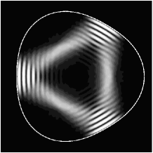
Theoretical predictions are confirmed by numerical simulation in which we chose a cavity defined by boundary that has symmetry, where . Figure 5 shows the four parity symmetry classes of this cavity. In notation , the sign is if the wave function is even (odd) with respect to the horizontal axis. Letter indicates a wavefunction that does not satisfy condition (10), while letter indicates a wave function that does. Therefore, solving Eq. (1) with yields two degenerate standing-wave eigenfunctions, as shown in Figs. 6(a) and (b), which are classified into and , respectively.
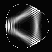
For , standing-wave eigenfunctions, as shown in Figs. 6(a) and (b), change into the rotating wavefunctions shown in Figs. 6(c) and (d), respectively. Then, as shown in Fig. 7, the frequency difference between the two eigenstates is proportional to angular velocity . Accordingly, the frequency difference can be observed in a rotating cavity with symmetry for .
5 Summary
In summary, we showed that designing the symmetry of cavity shape as symmetry gives degenerate resonance frequencies in non-rotating cavities and eliminates region where there is no resulting the shifts of resonant frequencies proportional to rotation rate.
Recently, semiconductor ring lasers [21, 22] and various types of microcavities [23, 24, 25] have been studied experimentally and theoretically toward the realization of small-sized rotation velocity sensors. We believe that our results will be useful for designing such rotation velocity sensors.
Acknowledgments
We thank T. Miyasaka for discussions and numerical simulations.
The work was supported by
the National Institute of information and Communication Technology
of Japan.

 |
 |
|---|---|
| (a) | (b) |
 |
 |
| (c) | (d) |
