Simultaneous slow phase and group velocities of light in an anisotropic metamaterial
Abstract
We study theoretically the effect of ultraslow phase and group velocities in an anisotropic metamaterial. The ultraslow phase propagation is induced by the hyperbolic dispersion relation. While the inherent physics underlying the slow group velocity are collective operations of the frequency and spatial dispersion. We show that a Gaussian wave packet exhibits simultaneous slow phase and group velocities which depend on the choice of incident angles and principal axis angles. The anisotrocpic metamaterial slab can be constructed and the ultraslow phase and group velocities can be measured experimentally.
pacs:
78.20.Ci, 41.20.Jb, 42.25.GyI Introduction
The unusual properties of the electromagnetic waves in a medium with simultaneously permittivity and the permeability were firstly introduced by Veselago about forty years ago Veselago1968 . The waves propagation in such media are quite counterintuitive. For example, the direction of energy flow for a plane wave is opposite to the direction of propagation. After the first experimental observation using a metamaterial composed of split ring resonators (SRR) Smith2000 ; Shelby2001 , the study of such materials has received increasing attention over the last few years. As noted earlier, both and are necessarily frequency dispersive in LHM. Since the frequency dispersion is important, the superluminal Ziolkowski2001 ; Woodley2004 ; Gupta2004 and the subluminal propagation Gupta2004 ; Gennaro2005 ; Dolling2006 in the LHM takes place.
It should be noted that we neglect bianisotropic effects despite the fact that they might be important for the characterization of some rings. While negative refraction is most easily visualized in an isotropic metamaterial, negative refraction can also be realized in anisotropic metamaterial, which does not necessarily require that all tensor elements of and have negative values Lindell2001 ; Parazzoli2003 ; Smith2003 ; Smith2004 ; Thomas2005 ; Luo2005 . If we just consider the spatial dispersion, the superluminal group velocity can be expected in the AMM with hyperboloid dispersion relation Luo2006 . While the real AMM constructed by SRR is highly dispersive, both in spatial and frequency sense Parazzoli2003 ; Smith2003 ; Smith2004 ; Thomas2005 , hence It is very necessary to extend the previous work and take the frequency dispersion into account.
In the present letter, we will investigate the simultaneous slow phase and group velocities of wave packet in an anisotropic metamaterial. The subluminal phase propagation is induced by the hyperbolic dispersion relations associated with the AMM. We describe a modulated Gaussian wave packet incident on the anisotropic metamaterial, which demonstrates in a straightforward manner that the peak of the localized wave packet displays interesting smultaneous slow phase and group velocities.
II Hyperbolic dispersion relation
It is currently well accepted that a better model is to consider anisotropic constitutive parameters, which can be diagonalized in the coordinate system collinear with the principal axes of the metamaterial. If we take the principal axis as the axis, the permittivity and permeability tensors have the following forms:
| (4) |
| (8) |
where and are the relative permittivity and permeability constants in the principal coordinate system (). It should be noted that the real AMM constructed by SRR is highly dispersive, both in spatial sense and frequency sense Parazzoli2003 ; Smith2003 ; Smith2004 ; Thomas2005 . So these relative values are functions of the angle frequency . A general study on the shape of the dispersion relation as function of the sign of these parameters has already been offered in Ref. Smith2003 . In this work, we are interested in the case of AMM with hyperbolic dispersion relation.
Without loss of generality, we assume that the wave vector locate at the plane (). Maxwell’s equations yield a scalar wave equation for E-polarized field . In free space, the accompanying dispersion relation has the familiar form:
| (9) |
where and are the and components of the incident wave vector, is the frequency, and is the speed of light in vacuum. We assume that there is an angle between the principal axis and the axis. For the given polarization, the waves equation yield the dispersion relation in AMM as
| (10) |
where and represent the and components of refracted wave vector, , and are given by
| (11) |
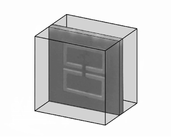
The material axes are normal to the surface of the rings. The cell structure is shown in Fig. 1. The metamaterial is formed by cutting the sheet into strips which are lined up with the appropriate periodicity. The permeability, , can be approximated by the Lorentz model
| (12) |
where , , and denote the magnetic resonate frequency, plasma frequency, and damping frequency, respectively. The characteristic resonance frequency GHz, plasma frequency GHz and GHz (). Ignoring the metallic structure, and assume the values of the background material which is dominantly air leading us to use Thomas2005 .
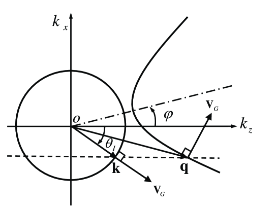
We assume here that the electric field is polarized along the axis. We choose to we find the corresponding requency contour is a hyperbola as shown in Fig. 2, where a plane electromagnetic wave is incident from free space into the AMM. We choose the axis to be normal to the interface, the axis in the plane of the figure, and the axis out of the plane of the figure. Due to the angular dispersion, the transmitted wave components may refract at slightly different angles. The values of refracted wave vector can be found by using the boundary condition and hyperbolic dispersion relation Luo2005 . The -component of the wave vector can be found by the solution of Eq. (10), which yields
| (13) |
the choice of sign of ensures that light power propagates away from the surface to the direction.
We now determine the angle of phase refraction. The incident angle of light in free space is and the refraction angle of the transmitted wave vector in AMM can be found by . From the boundary condition at the interface , the tangential components of the wave vectors must be continuous, i.e., . Thus the refracted angle of wave vector in the AMM can be easily obtained. When the interface is aligned an angle with the optical axes of the AMM, the hyperbolic dispersion relations will exhibit some interesting effects.
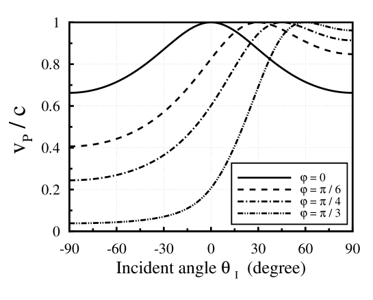
To get a deeper insight into the slow phase velocity, we plot the frequency contour in Fig. 2. The magnitude of varies as a function of its direction. When the refractive wave vector is approximately parallel to the asymptotic line of hyperbola, can be very large. The wave front travels in the AMM with the velocity of , so the ultra-slow phase velocity can be expected. The slow phase velocity in an AMM with different principal axial angles as shown in Fig. 3.
It should be noted that a wave group can be formed from plane waves with different frequencies or form plane waves with different wave vectors. Thus the difference in the phase and group velocities can be caused by media that are dispersive or anisotropic Kong1990 . The group velocity is a very important physical quantity because it identifies the speed of the maximum intensity of wave packet. The group velocity in anisotropic media can be defined as
| (14) |
where , and are unit cartesian vectors. Because of the anisotropy and angular dispersion, the group velocity is not necessarily parallel to the wave vector . Due to the resonance effect below the magnetic plasma frequency, the permeability functions undergo large changes with frequency, which results in and , hence the subluminal group velocity can be deduced.
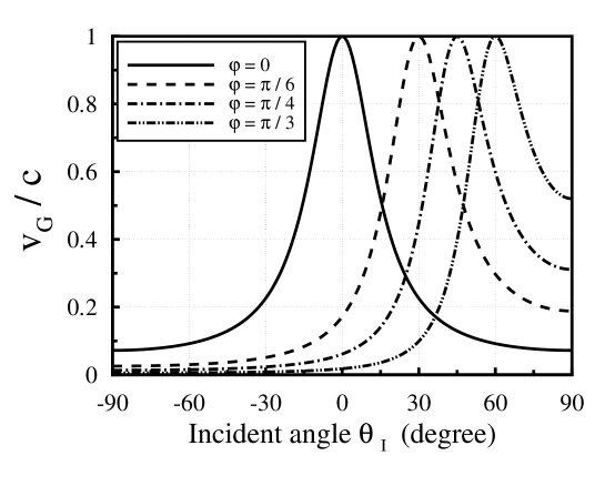
In Fig. 4, the group velocities in the AMM with different principal axes angle are plotted. It should be noted that the slow group velocity in the AMM is induced by the hyperbolic dispersion relation. While the inherent physics underlying the slow group velocity are collective operations of the frequency and spatial dispersion.
III Subluminal group propagation
To obtain a better physical picture of subluminal group velocity in AMM, a modulated Gaussian wave packet of finite width can be constructed. The field intensity distribution in free space is obtained by the Fourier integral and angular spectrum representation. Following the method outlined by Lu et al. Lu2004 , let us consider a modulated Gaussian wavepacket is incident from free space
| (15) |
where . we assume its Gaussian weight is
| (16) |
where is the spatial extent of the incident wave packet. We want the Gaussian wave packet to be aligned with the incident direction defined by the vector , which makes an angle with the surface normal.
Due to the angular dispersion and the anisotropy, the transmitted wave components may refract at slightly different angles. When the Gaussian wave packet enters the AMM, it will no longer maintain Gaussian, but becomes a tilted wave packet. Matching the boundary conditions for each component at gives the complex field in the form
| (17) |
where and is the transmission coefficient.
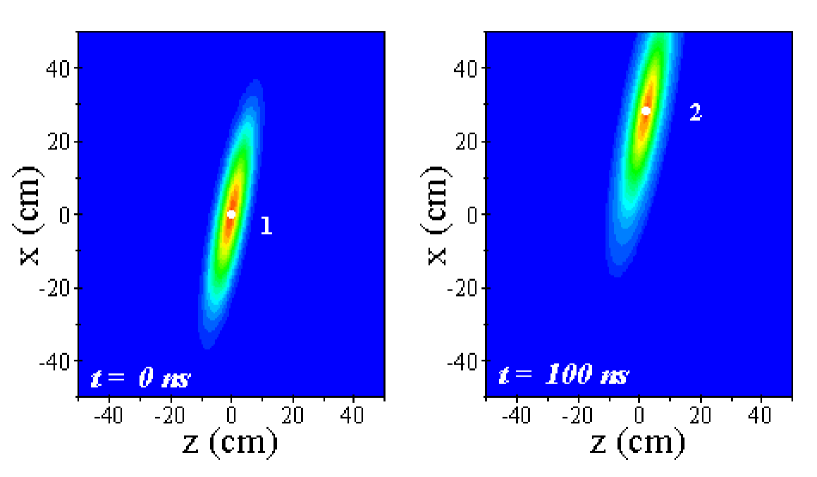
A close look at the tilted wave packet shows that the subluminal propagation of the peak is induced by the hyperbolic dispersion relation. Fig. 5 shows a closes view of the field intensity distribution of the wave packet propagating in the AMM. In a propagation time , the peak of the tilted Gaussian packet travels from point to point . In Fig. 5 we set the center wave vector with a incident angles . We mark on each position of the peak of wave packet at each of the two times. In the , the peak of wave packet moves from to . This propagating velocity corresponds to , which is almost exactly the analytical group velocity in Eq. (14), and the slow group velocity is demonstrated theoretically.
IV Discussion and conclusion
In summary, we have discussed simultaneous slow phase and group velocities of light in an anisotropic Metamaterial. It should be noted that the slow group velocity has completely different origin from those described in isotropic LHM Gupta2004 ; Gennaro2005 or ultracold gas of atoms Harris1999 ; Hau1999 , where the slow group velocity is caused by the frequency dispersion of the medium. In the case discussed here, the inherent physics underlying the slow group velocity are collective operations of the frequency and spatial dispersion. As far as we know, this kind of slow group velocity has not been recognized before. It should be mentioned, however, that the shape of Gaussian wave packet is distorted once it is incident into the AMM. It is shown that the simultaneously slow phase and group velocities can be measured experimentally.
Acknowledgements.
This work was supported by projects of the National Natural Science Foundation of China (No. 10125521 and No. 10535010), and the 973 National Major State Basic Research and Development of China (No. G2000077400).References
- (1) V. G. Veselago, Sov. Phys. Usp. 10 (1968) 509.
- (2) D. R. Smith, W. J. Padilla, D. C. Vier, S. C. Nemat-Nasser, and S. Schultz, Phys. Rev. Lett. 84 (2000) 4184.
- (3) R. A. Shelby, D. R. Smith, and S. Schultz, Science 292 (2001) 77.
- (4) R. W. Ziolkowski, Phys. Rev. E 63 (2001) 046604.
- (5) J. F. Woodley and M. Mojahedi, Phys. Rev. E 70 (2004) 046603.
- (6) S. D. Gupta, R. Arun and G. S. Agarwal, Phys. Rev. B 69 (2004) 113104.
- (7) E. D. Gennaro, P. V. Parimi, W. T. Lu, S. Sridhar, J. S. Derov and B. Turchinetz, Phys. Rev. B 72, 033110 (2004).
- (8) G. Dolling, C. Enkrich, M. Wegener, C. M. Soukoulis, and S. Linden, Science 312, 892 (2006).
- (9) I. V. Lindell, S. A. Tretyakov, K. I. Nikoskinen, and S. Ilvonen, Microw. Opt. Technol. Lett. 31, 129 (2001).
- (10) C. G. Parazzoli, R. B. Greegor, K. Li, B. E. C. Koltenbah, and M. Tanielian, Phys. Rev. Lett. 90, 107401 (2003).
- (11) D. R. Smith and D. Schurig, Phys. Rev. Lett. 90, 077405 (2003).
- (12) D. R. Smith, P. Kolinko, and D. Schurig, J. Opt. Soc. Am. B 21, 1032 (2004).
- (13) Z. M. Thomas, T. M. Grzegorczyk, B. I. Wu, X. Chen, and J. A. Kong, Opt. Express, 13, 4737 (2005).
- (14) H. Luo, W. Hu, X. Yi, H. Liu, and J. Zhu, Opt. Commun. 254, 353 (2005).
- (15) H. Luo, W. Hu, W. Shu, F. Li, and Z. Ren, Europhysics Letters 74, 1081 (2006).
- (16) J. A. Kong, Electromagnetic Wave Theory (John Wiley Sons, New York) 1990.
- (17) W. T. Lu, J. B. Sokoloff, and S. Sridhar, Phys. Rev. E 69 (2004) 026604.
- (18) S. E. Harris and L. V. Hau Phys. Rev. Lett. 82, 4611 (1999).
- (19) L. V. Hau, S. E. Harris, Z. Dutton, and C. H. Behroozi, Nature (London) 397, 594 (1999).