Nonlinear Finite Element Analysis of Nanoindentation of Viral Capsids
Abstract
Recent Atomic Force Microscope (AFM) nanoindentation experiments measuring mechanical response of the protein shells of viruses have provided a quantitative description of their strength and elasticity. To better understand and interpret these measurements, and to elucidate the underlying mechanisms, this paper adopts a course-grained modeling approach within the framework of three-dimensional nonlinear continuum elasticity. Homogeneous, isotropic, elastic, thick shell models are proposed for two capsids: the spherical Cowpea Chlorotic Mottle Virus (CCMV), and the ellipsocylindrical bacteriophage . As analyzed by the finite element method, these models enable parametric characterization of the effects of AFM tip geometry, capsid dimensions, and capsid constitutive descriptions. The generally nonlinear force response of capsids to indentation is shown to be insensitive to constitutive details, and greatly influenced by geometry. Nonlinear stiffening and softening of the force response is dependent on the AFM tip dimensions and shell thickness. Fits of the models capture the roughly linear behavior observed in experimental measurements and result in estimates of Young’s moduli of 280–360 MPa for CCMV and 4.5 GPa for .
Key words: viruses; atomic force microscopy; computer simulation; continuum mechanics; elasticity
Introduction
As confirmed by a scan of the RCSB Protein Data Bank (1), the structural biology techniques of X-ray crystallography and cryo-electron microscopy (cryo-EM) have enabled determination of the shape and structure of a multitude of macromolecules, in many cases locating individual atoms with resolution up to a few angstroms. In particular, these methods have been effective in elucidating the structures of the protein shells (capsids) of many viruses (2). However, despite (or perhaps because of) the wealth of detailed structural information made available by these methods, it remains a significant challenge to understand and predict the overall structural mechanics of capsids based on models of fundamental atomic interactions. Global deformations of capsids, such as those implicated in viral maturation (3) and infection processes (4, 5), can entail large-scale coordinated motions in which all atoms are involved. The shear number of atomic degrees of freedom in a viral shell makes molecular dynamics simulation of such processes unreasonable. In order to understand coarser-scale capsid mechanics, experimental and theoretical approaches are needed that describe the capsid structure in reduced terms.
Atomic force microscopy (AFM) is such a tool, able to explicate virus mechanics by measuring the force response due to indentation of a capsid. Recent AFM studies probing the mechanics of viral capsids (6, 7) have shown that they can be strong and yet highly elastic, even under significantly large deformations. A particularly interesting hallmark of these experiments is the linearity of force-indentation response. Prompted by this observation, Ivanovska et al. (6) interpreted AFM experiments on the bacteriophage by building theoretical models based on (linearized) small-strain, thin-shell, continuum elasticity, thus enabling quantitative estimation of three-dimensional elastic constants (e.g., the Young’s modulus) for the capsid. More recent experiments have measured a similarly linear force-indentation response for a completely different virus, Cowpea Chlorotic Mottle Virus (CCMV) (7), apparently affirming the appropriateness of linearized elasticity modeling. However, though linear-response theory does offer a description of these AFM experiments, it is not at all clear why a linear large-deformation response is observed in the first place. Indeed, in traditional solid mechanics, large deformations are frequently accompanied by a nonlinear force response, even when the material is perfectly elastic. The nonlinear elasticity of rubber materials is perhaps the most obvious example (8).
In this paper the a priori assumption of linearity is abandoned, and more general elastic continuum capsid models are developed and studied. Capsids are modeled in the context of finite-deformation hyperelasticity, wherein strains are not assumed to be small, such that the nonlinear effects of large displacements, rotations, and strains are considered. Previous linearized elasticity models of capsid indentation (6, 9) have also relied on reduced thin-shell theory (10, 11), under which the three-dimensional equations of elasticity are reduced to two dimensions, facilitating analytical solutions for simple loadings and geometries. However, thin-shell theory, as its name implies, is applicable only for shell structures with a thickness that is much smaller (by at least a few orders of magnitude) than the overall structural dimensions. In particular, thin-shell theory precludes transverse shear deformation, which though negligible for thin shells, is an important factor for thick shells. The nominal thickness of CCMV is just over 10% of its outer diameter, likely putting it outside the range of applicability for thin-shell analysis. Two options remain for analysis of a thick shell like the CCMV capsid. The first is to resort to shell theories which allow for shear deformation (10), and the second is to work within the general framework of 3-D continuum elasticity. In the present work, focus is on the latter, more general approach, and its differences with the former are briefly examined . Both of these strategies are difficult to employ in a closed-form analytical manner, and typically for scenarios involving large deformations and complex geometries or boundary conditions they require numerical solutions. The capsid indentation experiment is one such scenario, involving both large strains and geometric nonlinearities due to contact between the capsid and the substrate/AFM. In this work numerical solution is performed by the finite element method (12), the most popular and robust analysis technique for elasticity problems in engineering. Calculations are carried out using ABAQUS (13), a commercially available nonlinear finite element analysis software package.
Finite element simulations of AFM nanoindentation experiments provide a means for systematic study of the effects of model parameters on computed force-indentation response curves, thereby enabling validation and comparison to experiments. The inputs to the continuum elasticity models are of constitutive and geometric natures. To understand the influence of constitutive modeling choices, the classical (Hookean) linear stress-strain law is compared with nonlinear hyperelastic constitutive laws. Also, the dependence of force-indentation curves on capsid dimensions and AFM-tip loading geometry is demonstrated. The results show that the nonlinear contact interaction of the AFM tip with the capsid has important qualitative and quantitative influence on the structural response.
The experimental studies (6, 7) that have motivated this work measured the nanoindentation response of two viruses: Cowpea Chlorotic Mottle Virus (CCMV) and bacteriophage . CCMV is a roughly spherical plant virus of about 28 nm in diameter. Its protein capsid, which protects a single-stranded RNA genome, is assembled from identical protein subunits arranged into a truncated icosahedron with a triangulation number =3, according to the Caspar-Klug classification scheme for icosahedral viruses (14). is a bacteriophage (i.e., a virus that attacks bacteria) with a roughly ellipsocylindrical capsid that protects a double-stranded DNA genome. The capsid is comprised of 235 protein subunits, arranged into a prolate shell with a center cylindrical region and two icosahedral end caps (15).
The following section describes the mechanics framework and the finite element formulation for the models, and presents the idealized structural models of CCMV and . Next, results are presented of simulations of nanoinentation of CCMV along with some estimates of effective elastic moduli. Because its more symmetric shape makes it a simpler candidate for modeling, CCMV is focused on as the subject of a series of parametric studies on model parameters. First the sensitivity of the model to changes in constitutive laws is assessed. Despite the presence of large strains in simulations, no significant difference in overall force-indentation response is observed for the three different models. Secondly the influence of the AFM tip geometry and shell thickness on the overall response is examined. These geometric properties are shown to produce both stiffening and softening nonlinearities in the structural force response. For comparison purposes, the computed indentation response of a is shown, and an estimate of its effective elastic moduli is made.
Models and Methods
Modeling capsid geometry
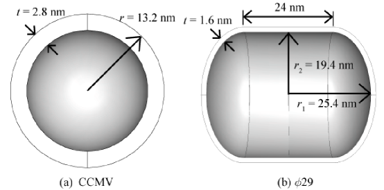
The native atomic structure of CCMV was determined to within Å by Speir et al. (4) using X-ray crystallography and cryo-electron microscopy. In this study, the capsid was shown to be a icosahedral shell, composed of protein subunits organized with regions of five-fold symmetry (pentamers) and six-fold symmetry (hexamers) that form protrusions from the capsid surface, making the thickness of the shell highly nonuniform. For the outer radius of CCMV, Speir et al. (4) measured a maximum value of nm and a minimum value of nm. The average outer Radius is nm (16). For the inner surface of the capsid they specify a minimum radius of nm and an average radius of nm. Here CCMV is idealized as a uniformly thick spherical shell as shown in Fig. 1(a). It is not immediately clear what uniform dimensions for the idealized shell would best represent the highly nonuniform physical dimensions of the actual capsid. As a starting point, average radius values are adopted for the inner and outer surfaces, which from (4) are nm and nm, such that the idealized thickness is nm. Given the arbitrariness of adopting average dimensions for the idealized model, a parametric study is done to examine the influence of these choices on the model results.
The second virus of the study, bacteriophage , has a less symmetric but more uniform structure, as determined by Tao et al. (15) using cryo-electron microscopy. Its capsid is formed by two =3 icosahedral caps connected by a cylindrical region of hexamers. The average thickness of the capsid is nm. The two outer diameters are known to be nm from the apex of one endcap to another and nm across the cylindrical region (15). The capsid is modeled by a center cylindrical region nm in length connecting two ellipsoidal endcaps. Ellipsoidal endcaps (rather than spherical) are chosen as there is a disparity between the measured dimension from the center to the cylindrical section ( nm) and from the center to the apex of the endcap ( nm). If the endcaps were made spherical, and the length of the cylindrical region chosen to match the reported 24 nm value, then the apex to apex diameter of the model would be much larger than the reported value. Model dimensions are summarized in the schematic diagrams in Fig. 1.
Theoretical background and computational methodology
Following the standard definitions of finite deformation continuum mechanics (17, 18), the deformation of a body is described by the one-to-one deformation mapping , which maps material point at position in the reference configuration of the body to point in the deformed configuration of the body. The deformation gradient tensor is denoted , the right Cauchy-Green deformation tensor and the Green strain tensor . The volume change ratio of current to reference volume is given by the determinant of the the deformation gradient, . Also, in the context of compressible large-strain elasticity, it is helpful to introduce isochoric (volume-preserving) deformation tensors and .
Constitutive theory for hyperelastic materials postulates the existence of a strain energy density function , which gives the stored elastic energy per unit reference volume at every material point in the body. The stress response of a hyperelastic material is then given in terms of the first Piola-Kirchhoff stress tensor or the second Piola-Kirchhoff stress tensor .
Mechanical equilibrium can be enforced by minimizaton of the total mechanical energy (including work of contact forces). The finite element method approximated the nonlinear elasticity problem by interpolating the deformation mapping among the deformed positions of the vertices (nodes) of a polyhedral mesh, and solving for the nodal positions which best minimize energy. The finite element equilibrium equations are nonlinear in the unknown deformed nodal positions because of the nonlinearities in the constitutive expressions for stress and (for the present context) in the contact conditions which define external forces.
Constitutive laws
In this work, three particular hyperelastic models are employed: St. Venant-Kirchhoff, Neo-Hookean, and Mooney-Rivlin. The so-called St. Venant-Kirchhoff model, is given by the strain energy function
| (1) |
The chief appeal of this material model is that the resulting (second Piola) stress response is linear in the Green strain, and is, in a sense, akin to Hooke’s law for isotropic (infinitesimal-strain) linear elasticity. Linearization of this stress response for vanishingly small values of the displacement gradient identifies and as the initial Lamé constants.
For isotropic compressible hyperelastic materials it can be convenient to define the strain energy function in a decoupled representation as
where describes the volumetric response, and describes the isochoric response in terms of the first two principal invariants of . The simplest example of such a constitutive law, the Neo-Hookean model defines the isochoric response to be simply linear in the first invariant:
| (2) |
Emerging from the statistical mechanics of a Gaussian chain (19), the Neo-Hookean form has some justification as a highly idealized constitutive model for polymers and proteins. Linearization of the Neo-Hookean stress response yields as the initial shear modulus. The Mooney-Rivlin model can be though of as an extension of the Neo-Hookean to include the lowest-order dependence on the second invariant:
| (3) |
Linearization of Mooney-Rivlin for small strains gives an initial shear modulus of . For both Neo-Hookean and Mooney-Rivlin models, we choose a simple quadratic volumetric response such that linearization renders as the initial bulk modulus, consistent with initial Lamé constants, and .
Simulation of capsid nanoindentation
AFM nanoindentation of capsids is simulated by the finite element method, using the commercially available package ABAQUS (13). The models described above are meshed with finite elements, and the capsid meshes are compressed between substrate and AFM tip. The substrate and AFM tip are both modeled as rigid. The substrate has the geometry of a flat plate, whereas the AFM tip is given a spherical shape with a nominal radius of about 14 nm, consistent with geometry of the tips used in the experiments of Ivanovska et al. (6) and Michel et al. (7). Though the spherical CCMV model obviously has no intrinsic orientation, the same is not true for the ellipsocylindrical . Again motivated by the experiments of Ivanovska et al. (6), the model is oriented such that compression is simulated along the short axis of the capsid. Noting presence of symmetries in the capsid and loading geometries, it seems reasonable to expect deformation to obey the same symmetries. Hence only one-quarter of each capsid is meshed, and symmetry boundary conditions along the boundaries are enforced. Meshed model assemblies are shown in Fig. 2.
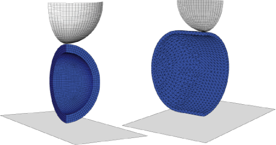
Contact of the rigid tip and substrate with the deformable capsid is modeled as frictionless, such that Lagrange-mulitiplier contact forces are introduced normal to the contact interfaces, in order to prevent interpenetration. The progressive compression of the capsid is achieved by an incremental, quasi-static, displacement-controlled process, where each increment involves a small upward displacement of the rigid substrate followed by iterative solution of the nonlinear finite element equilibrium equations consistent with contact constraints. For each incremental displacement of the substrate, the total contact force at each contact interface is computed, allowing construction of a force-deflection curve for the indentation process.
Nanoindentation of CCMV
As described in the previous section, parameters defining the spherical model of CCMV are of two types: geometric and constitutive. The simulations described here are designed to separately and quantitatively understand the effects of these parameters on capsid indentation. The influence of capsid dimensions is considered by fixing the radius of the midsurface of the shell (equidistant from the inner and outer surfaces) at nm, while varying the thickness from 1 nm to 5 nm (roughly reflecting the range of physical thickness over the actual capsid shell). A range of AFM tip geometries is also considered, from a rather sharp tip of radius 3.5 nm to a completely flat tip (i.e., infinite radius).
The three consititutive theories described above—St. Venant-Kirchhoff, neo-Hookean, and Mooney-Rivlin—are parameterized in a manner such that they linearize consistently with initial Lamé constants related to initial Poisson ratio and initial Young’s modulus by
Informal comparisons showed that the model results were quite insensitive to the choice of Poisson ratio. Because proteins tend toward behaving incompressibly in their elasticity, an only slightly compressible Poisson ratio of is chosen here for all simulations. As can be seen from the definitions earlier, because the simulation is displacement-controlled, the Young’s modulus acts effectively as a simple proportionality factor for the stress response of the material (and hence also for the force response of the entire shell). Therefore, simulation results can be normalized by , avoiding the need for running a series of simulations over a range of values.
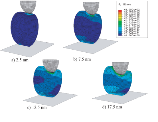
Parametric studies of geometric and constitutive effects are described in the following section. As a representative example, consider a simulation of CCMV with the nominal dimensions from Fig. 1 (outer radius of 13.2 nm and a thickness of 2.8 nm), described by St. Venant-Kirchhoff elasticity, indented by a spherical rigid AFM tip of radius 14 nm. For a capsid with Young’s modulus of MPa (on the order of what’s expected for typical protein material (20)), Fig. 3 shows a sequence of deformed capsid shapes, color coded by von Mises stress (21) at several intervals during the indentation process.
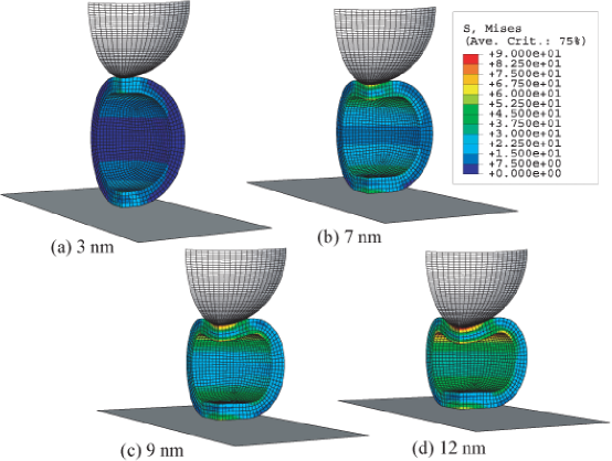
Fig. 3 shows that as AFM indentation increases during simulation, elastic stresses build and are distributed through the thickness of the capsid wall (as indicated by the contours of von Mises stress). At the outset, the stress is highest at and around the point of contact between the AFM tip and the top of the capsid, and is more uniformly distributed through the thickness away from the contact region. As the substrate displacement continues, the stress is increasingly concentrated on the inside surface of the capsid. In general at later stages in the indentation, the von Mises stress decreases in magnitude through the thickness, taking its lowest value at the center of the capsid wall, consistent with the interpretation that bending becomes a more dominant load-carrying mechanism. For this and all other CCMV simulations, indentation is carried forward until the substrate displacement reaches 30% of the capsid diameter, approximately the point of failure in experiments (7). At this point in this representative simulation, the largest von Mises stress is about 90 MPa and the maximum magnitude of the principal strains is about 15%, clearly outside the range of applicability of small strain linear elasticity. Since many materials have ultimate strengths that are in the range of 1–10% of their Young’s moduli (20), the maximum stress of 90 Mpa far exceeds this rule of thumb for indicating failure. This suggests the capsid is qualitatively similar to rubber materials, which typically have higher ultimate strengths and lower Young’s moduli.
Given the magnitude of strains, along with the significant changes in contact geometry throughout the simulation depicted in Fig. 3, it is somewhat surprising that the corresponding force-indentation curve, shown in Fig. 4, exhibits only very subtle nonlinearity. For very small displacements of the substrate, there is a noticeable positive curvature in the force response. This corresponds to the initial part of the indentation, where deformation gradually spreads through the thickness of the shell as the contact area between tip and capsid grows. In the limit of small deformations, this should lead to a Hertz-like contact force scaling, which from linear elasticity is expected to take the form (10, 11), where is the total contact force and is the indentation or change in capsid height. This expected scaling is consistent with initial convexity of the simulated force response.
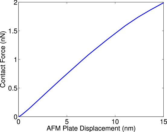
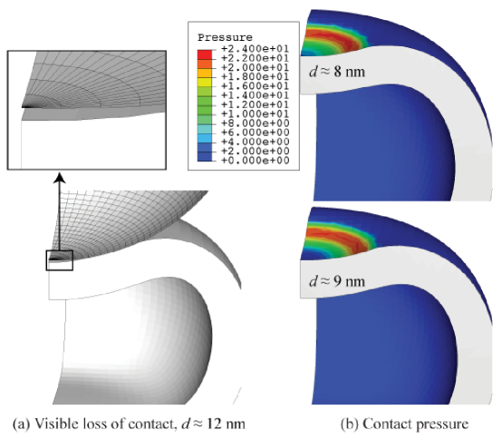
At larger indentations, the curve becomes remarkably linear over a large range, before eventually softening around nm as bending deformations of the shell become more severe. It is in this range in the simulation that the contact pressure near the center of the AFM tip contact region begins to decrease to the point where eventually full contact is lost and a gap opens between the AFM tip and the apex of the capsid. The contact region is from then on defined by a circular ring. Fig. 5(a) shows a close-up side view of the AFM tip and the top of the capsid illustrating the separation of the capsid away from the AFM tip. Fig. 5(b) shows the contact pressure between the AFM tip and capsid surfaces at indentations of nm and nm, just after the capsid and AFM tip separate. The blue area in the center of the top portion of the capsid represents zero contact pressure, and the circular ring area where the AFM tip and capsid are still in contact can clearly be seen. Zero contact pressure is indicative of a loss of contact several nanometers before the separation (seen in Fig. 5a) is visible. The inner gray region in Fig. 5(a) is the area of the two surfaces that are no longer in contact. This separation of the capsid apex from the AFM tip geometrically resembles the so-called “snap-through” buckling of arches and thin shells (10, 22). This nonlinear contact effect is not to be confused with a geometric instability or equilibrium bifurcation, which would be marked by a drop in the force-indentation curve. However, the softening of the force-indentation curve is qualitatively similar to “snap-through” behavior, and consistent with a transition of the primary load-bearing mechanism from stretching to bending of the shell surface. The absence of a drop in force for this reversibly elastic model perhaps suggests that the failure experimentally observed by Michel et al. (7) may be related to instability in the constitutive response of the protein material.
Parametric studies
Constitutive laws.
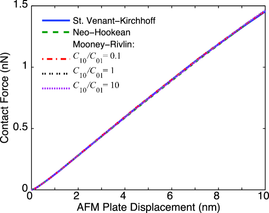
As shown in the previous section, AFM indentation is capable of inducing significant strains in a capsid shell. The experimentally-demonstrated fact that CCMV capsids remain elastic despite such deformations, puts them in a very special class of materials. Phenomenological constitutive theory for large-strain nonlinear-elastic materials has traditionally focused on the response of rubber-like materials. Two of the lower-order theories for rubber-like materials: neo-Hookean and Mooney-Rivlin, are employed here to get a sense for how important constitutive details are relative to geometric nonlinearities in determining the overall shape of the force-indentation curve. Fig. 6 compares force-indentation responses for capsids modeled with neo-Hookean and Mooney-Rivlin to that of the linear St. Venant-Kirchhoff model. The parameters for all of these simulations are identical to those the representative CCMV model above, with the dimensions of the shell taken from Fig. 1, a Poisson’s ratio of and an initial Young’s modulus of MPa. The coefficients of three-parameter Mooney-Rivlin model are determined by specifying the fraction in addition to and . Three values of this fraction are considered, such that the first invariant is weighted respectively less, evenly, and more than the second invariant. Fig. 6 clearly demonstrates that the force-indentation curves for all of these constitutive models are practically coincident throughout the entire deformation. This clarifies that the details of the constitutive response are not centrally important to the shape of the force-indentation curve. It suggests rather that the geometry of the shell, and the geometry of loading are more influential in determining the indentation response. Furthermore, these results support the appropriateness of the linear stress-strain law. Apparently, despite the presence of rather large strains, constitutive nonlinearities are masked from the overall structural response. This is likely due to the fact that the strains over much of the capsid are significantly smaller than the maximum value, such that locally even the nonlinear models are in the linear response regime.
AFM tip size.
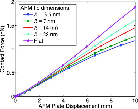
In the experiments of (6, 7) capsids rest on a flat substrate and are compressed by an AFM tip which is roughly hemispherical. The AFM tip radius is on the order of the outer radius of the CCMV capsid, but exact determination of the dimensions is difficult. Hence there is a need to determine the importance of the modeled AFM tip size on the resulting contact behavior. Simulations were performed varying the AFM tip radius from one-quarter of its nominal size (14 nm) to infinite (treating the AFM tip as a second flat plate), and the resulting contact force curves are compared in Fig. 7. At displacements of nm, when failure is experimentally observed, the contact force varies by . When approaching either extreme in the size of the AFM tip, be it of infinite radius (a flat plate) or nearing a point load (one quarter of the initial radius), the results change only slightly. Also notable is the subtle change in shape of the force-indentation curve as the tip radius is changed. Softening of the force response, noted earlier to occur along with a separation of the capsid apex from the tip, is accentuated by smaller tips which induce more bending deformation in the capsid. Indeed, over the range of deformation simulated, this softening is completely absent when the tip is modeled as a flat plate. In this case bending deformations near the apices is limited and the slope of the force-indentation curve is monotonically increasing.
Capsid thickness.
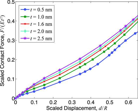
As noted earlier, the Young’s modulus, , acts as a simple proportionality factor for stress and force responses to indentation, allowing for simple renormalization of the force-indentation response to eliminate dependence on . The same cannot be said for the scaling with capsid thickness . Because nonlinear geometric effects are included in the finite element model, it is difficult to predict analytically the precise scaling with thickness. Roughly, thickness scaling should follow that of linearized thin-shell theory wherein force goes as the square of thickness (10, 11), but this is only an approximation. Fig. 8 clearly shows the change in behavior as the thickness of the capsid is varied, while holding the average radius constant at nm.
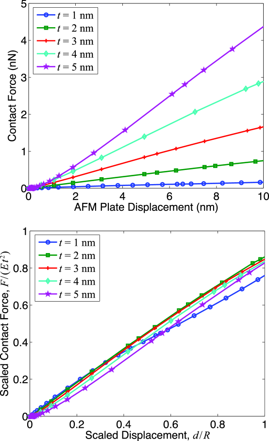
For deformation of a thin shell, linearized elasticity theory gives a force displacement scaling , where is the shell thickness, is the size of the shell, and is the Young’s modulus (10, 11). In general the proportionality factor is a function of the loading and boundary conditions of the problem. For the present application, Fig. 8(b) plots the the contact force, normalized by , versus indentation, normalized by CCMV’s average radius . Even though this model considers geometric nonlinearities, the curves for different thicknesses nearly collapse to the linearized scaling, with an average proportionality factor of 0.8, i.e.,
Assuming a nominal thickness of nm and average radius of nm for CCMV, the Young’s modulus can be estimated by relating the experimentally measured spring constant of the capsid to the approximate theoretical spring constant of . In this way, the Young’s modulus is calculated to be MPa for the empty wild-type capsids and MPa for the empty subE mutant capsids. Notably, these modulus values are similar to those of soft plastics, such as Teflon, and are slightly smaller than characteristic values for single proteins as measured in single molecule experiments (20). This is consistent with the notion that much of the local deformation of actual capsids may be sustained in the regions between protein subunits, such that the overall stiffness of the capsid structure is less than that of the individual proteins.
The renormalized plot in Fig. 8(b) also reveals more clearly how deviations from linearity in the force response depend on shell thickness. For larger thicknesses, the stiffening Hertz-like response near the origin is more pronounced, while for smaller thicknesses softening of the force response at larger indentations is more prominent. The mechanisms for both of these nonlinear effects are related to changes in the geometry of contact between the AFM tip and the capsid shell, which are primarily controlled by the ease with which the shell can be bent to accommodate the rounded tip. Notably, for thicknesses near the average physical thickness of the CCMV capsid (2.8 nm), these two nonlinear effects (one stiffening and the other softening) seem to balance each other out resulting in a nearly linear response. It is perhaps reasonable to conjecture that these mechanisms have roles in producing the linearity observed experimentally for the actual capsid.
Nanoindentation of
A model assembly similar to that applied to CCMV above has been employed to simulate indentation of , mimicking the experiments of Ivanovska et al. (6). As the same experimental setup was involved in experiments on both capsids, here the AFM tip geometry is again modeled as spherical with a radius of 14 nm. However, has a significantly larger capsid than CCMV, by a factor of two in diameter. Hence, the same 14-nm AFM tip is smaller relative to . In addition, the nominal thickness of the capsid relative to its average radius is much smaller than that of CCMV (by a factor of four). Recalling that softening of the force response for CCMV was accentuated both by smaller tip size and smaller shell thickness, it is not surprising to see in Fig. 9 that the simulated force-indentation response of exhibits more significant softening at moderate to large indentations over a range of modeled thicknesses. The response of adheres reasonably well to the linearized scaling, however the shell-thickness-related softening nonlinearity appears more pronounced than for CCMV.
From Fig. 1 the nominal capsid thickness nm, and a nominal radius (chosen to be the average value between the smaller and larger radii, nm) are chosen such that an estimate of the linearized proportionality factor, and capsid Young’s modulus can be made. From Fig. 9, for a wide range of thicknesses, a good estimate of the average proportionality factor is . Thus, from the experimentally determined spring constant of the capsid, the Young’s modulus is estimated to be GPa.
As seen in the sequence of deformed shapes in Fig. 10, the progression of the von Mises stress is localized to the upper and lower regions of the capsid which undergo the highest deformation. However, the upper region of the capsid develops stress much more quickly, and with a higher magnitude. Due to the lack of axisymmetry of the capsid about the indentation axis, there is a region away from the region of contact with the AFM tip where the stress begins to be prominent at nm: the inner surface of the upper portion of the capsid nearest to the center. However, this only occurs at displacements in the simulation that exceed the displacements at which failure occured experimentally. At the point when drops in the force are seen experimentally, nm, the highest stresses in the simulated capsid are MPa for GPa. This is on par with the ultimate strength of typical protiens (20), suggesting that breakage of the capsid could very well be the cause of failure in experiments. The highest strain in the capsid is at nm, and occurs on the inner surface of the capsid directly under the AFM tip. However, unlike the CCMV simulations, no separation of the capsid away from the AFM tip is observed.
Discussion
A core objective of this work has been to illuminate some of the mechanisms responsible for the linear force-indentation responses measured for the capsids of viruses CCMV and . The acknowledgment that these nanoscale structures act as elastic shells prompts the question of how similar they are mechanically to macroscopic shells, which are modeled well by continuum elasticity theory. It is not clear how to answer this question directly given that a consise quantitative theoretical description of the local mechanics of the individual constituent capsid proteins and their interactions is currently out of reach. In the absence of such detailed constitutive understanding, experminents such as those performed with atomic force microscopy (6, 7) provide a coarse-grained probe to measure the global structural response of capsid shells. The continuum modeling in this work serves as a convenient coarse-grained theoretical complement, partially clarifying what features of the observed experimental results are generic for shells, and what features require detailed constitutive knowledge for explanation.
The results here demonstrate that the generally nonlinear shape of the force-indentation response for a homogeneous spherical shell is affected significantly by the dimensions of the indentor and the shell itself. In particular, stiffening at low force/indentation, similar to Hertz response for solid bodies in contact, is characteristic of the indentation response for thicker shells with dimensions like the CCMV capsid. Small AFM tips and small capsid thicknesses both facilitate bending deformation, which generally softens structure at higher indentations. Large tip sizes and shell thicknesses can have the opposite effect, leading to further stiffening of the force response at larger indentations.
Consideration of nonlinearites in modeling capsid nanoindentation has an impact on the interpretation of experiements. Previous linearized elasticity models constructed by Ivanovska et al. (6) estimated a Young’s modulus for of GPa. This result appears mainly to be a function of two things: a proportionality factor found analytically for a spherical shell with point loads applied at the top and bottom, and a finite element model also designed with point loads with the capsid modeled as a geodesic ellipsoid. Together, these factors lead to an estimate of the Young’s modulus which is smaller than that of the present model. Clearly such difference is to be expected with the point loading exchanged for a finite-sized tip. However, both the previously reported value and the value reported here show the capsid to have a stiffness in the range of GPa.
The continuum shell models presented here may also help to explain how the linearity of the experimentally measured force-indentation responses of (6) and CCMV (7) can persist despite the pervasiveness of nonlinearity in the system. The dimensions of the AFM tips and capsids in recent experiements on CCMV are in a range in which the nonlinear stiffening and softening effects seem to balance each other so that the modeled elastic force-indentation response is close to linear. This result suggests that similar experiments done with AFM tips or capsids of other dimensions might reveal force-indentation responses which are nonlinear even in the elastic regime. However, though the measured response of , which has significantly different dimensions from CCMV, is also linear, the continuum models here still show noticeable nonlinearity. This indicates a deficiency of the present continuum models for precise prediction of capsid behavior. This could perhaps be remedied by a more accurate representation of the geometry of the . Alternatively, the models could be improved with a more informed choice of constitutive law, although the constitutive models employed here, which are capable of significant nonlinearities, did not significantly affect capsid shell response.
Another drawback to the isotropic, homogeneous, geometrically simple model is that it does not produce drops in contact force that are experimentally observed at deformation. These drops are signs of failure of capsid structure, which in general could be triggered by geometric instability (buckling) or local failure of the material (e.g., bond-breaking). Over the relevant range of dimensions, the models in this work did not exhibit any geometric instabilities. However, the present model does not take into account any of the geometric complexities present in the molecular structure; although spherical in an average sense, the CCMV capsid is faceted into distinct regions of pentamers and hexamers and there are specific and finite points where the subunits are joined through chemical bonding. The same is true for . These geometric inhomogeneities could change the buckling characteristics of the structure. Also, the present model neglects the effects of “pre-stressing” consistent with the hypothesis of Lidmar et al. (9) that the icosahedral vertices of spherical capsids act as disclinations in an otherwise hexagonal protein lattice. In fact, based on this hypothesis, the recent coarse-grained molecular-dynamics simulations of Vliegenthart and Gompper (23) reveal that buckling, marked by force drops, is indeed possible during capsid indentation.
Because the nonlinear elasticity model did not turn out to predict any drop in force due to geometric instability, it may be inferred that the mechanism of failure during the experiment is likely to be, at least in part, capsid breakage. To test this hypothesis, a more complex model would be needed that describes the physics of interactions between the subunits and the more variated structure of the capsid. A plausible scenario is that the capsid structure fails at the noncovalent bonds between subunits. It is possible that a true atomic model would be required to capture points of failure nucleation/initiation.
References
- Berman et al. (2003) Berman, H.M., K. Henrick, and H. Nakamura. 2003. Announcing the worldwide protein data bank. Nature Structural Biology, 10(12):980. http://www.pdb.org/.
- Baker et al. (1999) Baker, T.S., N.H. Olson, and S.D. Fuller. 1999. Adding the third dimension to virus life cycles: Three-dimensional reconstruction of icosahedral viruses from cryo-electron micrographs. Microbiology and Molecular Biology Reviews, 63:862–922.
- Wikoff et al. (2006) Wikoff, W.R., J.F. Conway, J.H. Tang, K.K. Lee, L. Gan, N.Q. Cheng, R.L. Duda, R.W. Hendrix, A.C. Steven, and J.E. Johnson. 2006. Time-resolved molecular dynamics of bacteriophage hk97 capsid maturation interpreted by electron cryo-microscopy and x-ray crystallography. Journal of Structural Biology, 153:300–306.
- Speir et al. (1995) Speir, J.A., S. Munshi, G.J. Wand, T.S. Baker, and J.E. Johnson. 1995. Structures of the native and swollen forms of cowpea chlorotic mottle virus determined by x-ray crystallography and cryoelectron microscopy. Structure, 3(1):63–78.
- Bothner et al. (1998) Bothner, B., X.F. Dong, L. Bibbs, J.E. Johnson, and G. Suizdak. 1998. Evidence of viral capsid dynamics using limited proteolysis and mass spectrometry. Journal of Biological Chemistry, 273(2):673–676.
- Ivanovska et al. (2004) Ivanovska, I.L., P.J. de Pablo, B. Ibarra, G. Sgalari, F.C. MacKintosh, J.L. Carrascosa, C.F. Schmidt, and G.J.L. Wuite. 2004. Bacteriophage capsids: Tough nanoshells with complex elastic properties. PNAS, 101:6700–6705.
- Michel et al. (2006) Michel, J.-P., I.L. Ivanovska, M.M. Gibbons, W.S. Klug, C.M. Knobler, C.F. Schmidt, and G.J.L. Wuite. 2006. Nanoindentation studies of full and empty viral capsids and the effects of capsid protein mutations on elasticity and strength. Proc. Nat. Acad. Sci., 103(16):6184–6189.
- Ogden (1997) Ogden, R.W. 1997. Non-linear Elastic Deformation. Dover Publications, Mineola, NY.
- Lidmar et al. (2003) Lidmar, J., L. Mirny, and D.R. Nelson. 2003. Virus shapes and buckling transitions in spherical shells. Phys. Rev. E, 68:051910–20.
- Timoshenko and Woinowsky-Krieger (1959) Timoshenko, S. and S. Woinowsky-Krieger. 1959. Theory of Plates and Shells. McGraw-Hill, New York.
- Landau and Lifshitz (1986) Landau, L.D. and E.M. Lifshitz. 1986. Theory of Elasticity. Pergamon Press, Oxford.
- Zienkiewicz and Taylor (2005) Zienkiewicz, O.C. and R.L. Taylor. 2005. The Finite Element Method. Butterworth-Heinemann, Boston, MA.
- Aba (e RI) ABAQUS (ABAQUS Inc., Providence, RI).
- Caspar and Klug (1962) Caspar, D.L. and A. Klug. 1962. Physical principles in the construction of regular viruses. Cold Spring Harb. Symp. Quant. Biol., 27:1–24.
- Tao et al. (1998) Tao, Y.Z., N.H. Olson, W. Xu, D.L. Anderson, M.G. Rossmann, and T.S. Baker. 1998. Assembly of a tailed bacterial virus and its genome release studied in three dimensions. Cell, 95(3):431–437.
- Shepherd et al. (2006) Shepherd, C.M., I.A. Borelli, G. Lander, P. Natarajan, V. Siddavanahalli, C. Bajaj, J.E. Johnson, III C.L. Brooks, and V.S. Reddy. 2006. Viperdb: A relational database for structural virology. Nucl. Acids Res., 34(Database Issue):D386–D389. http://viperdb.scripps.edu/index.php.
- Gurtin (1981) Gurtin, M.E. 1981. An Introduction to Continuum Mechanics. Academic Press, New York.
- Holzapfel (2001) Holzapfel, G.A. 2001. Nonlinear Solid Mechanics: A Continuum Approach for Engineering. Wiley, New York.
- Treloar (1975) Treloar, L.R.G. 1975. The Physics of Rubber Elasticity. Clarendon Press, Oxford.
- Howard (2002) Howard, J. 2002. Mechanics of Motor Proteins and the Cytoskeleton. Sinauer Associates, Sunderland, MA.
- Ugural (2003) Ugural, A.C. 2003. Advanced Strength and Applied Elasticity. Prentice Hall PTR, Upper Saddle River, NJ.
- Calladine (1998) Calladine, C.R. 1998. Theory of Shell Structures. Cambridge University Press, New York.
- Vliegenthart and Gompper (2006) Vliegenthart, G.A. and G. Gompper. 2006. Mechanical deformation of spherical viruses with icosahedral symmetry. Biophys. J., 91(3):834–841.