Nonlinear photonic crystal fibres: pushing the zero-dispersion toward the visible
Abstract
The strong waveguide dispersion in photonic crystal fibres provides unique opportunities for nonlinear optics with a zero-dispersion wavelength far below the limit of set by the material dispersion of silica. By tuning the air-hole diameter , the pitch , and the number of rings of air holes , the strong waveguide dispersion can in principle be used to extend well into the visible, albeit to some extend at the cost of multimode operation. We study in detail the interplay of the zero-dispersion wavelength, the cut-off wavelength , and the leakage loss in the parameter space spanned by , , and . As a particular result we identify values of ( nm) and ( nm) which facilitate the shortest possible zero-dispersion wavelength ( nm) while the fibre is still single-mode for longer wavelengths.
pacs:
42.70.Qs, 42.81.Dp, 42.81.-i1 Introduction
Photonic crystal fibres (PCFs) [1, 2] have led to an enormous renewed interest in nonlinear fibre optics [3, 4, 5, 6]. In particular, the strong anomalous group-velocity dispersion has facilitated visible super-continuum generation [7], which apart from being a fascinating and rich non-linear phenomenon [8] also has promising applications including frequency-comb metrology [9, 10] and optical coherence tomography [11].
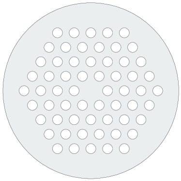
The regular triangular arrangement of sub-micron air-holes running along the full length of the fibre [12, 13], see Fig. 1, is a key concept for the realization of strong anomalous chromatic dispersion which arises in a competition between material dispersion and wave-guide dispersion originating from the strong transverse confinement of light. At the same time the strong transverse confinement of light also serves to dramatically decrease the effective area and increase the non-linear coefficient [14] so that very high optical intensities may be achieved relative to the input power.
The zero-dispersion wavelength may be tuned down to the visible [15, 16] by carefully increasing the normalized air-hole diameter while at the same time decreasing the pitch . However, in many cases the very short zero-dispersion wavelength is achieved at the cost of multi-mode operation. Furthermore, the reduction of the pitch may require a large number of rings of air holes in order to circumvent leakage loss.
In this paper we in detail study the complicated interplay of the zero-dispersion wavelength , the cut-off wavelength , and the leakage loss in the parameter space spanned by , , and . As a particular result we identify values of and which facilitate the shortest possible zero-dispersion wavelength while the fibre is still single-mode for longer wavelengths, i.e. .
2 Competition between material and wave-guide dispersion
The linear dynamics and response of a waveguide is typically studied within the framework of temporal harmonic modes, , where is a solution to the vectorial wave equation
| (1) |
Here, is the spatially dependent dielectric function of the composite air-silica dielectric medium, see Fig. 1, and is the corresponding refractive index.
Solving the wave equation, Eq. (1), provides us with the dispersion relation which contains all information on the spatial-temporal linear dynamics of wave packets and it is furthermore important input for studies of non-linear dynamics. However, quite often the dynamics and evolution of pulses are quantified by the derived dispersion parameters with being recognized as the inverse group velocity. The group-velocity dispersion is in fiber optics commonly quantified by the dispersion parameter (typically in units of ps/nm/km) which can be written in a variety of ways including
| (2) |
where is the free-space wavelength. The dispersion in the group velocity makes different components in a pulse propagate at different speeds and thus pulses will compress or broaden in time depending on the sign of . The zero-dispersion wavelength , defined by , is thus of particular relevance to pulse dynamics in general and non-linear super-continuum generation in particular. By pumping the fiber with high-intensive ultra-short nano and femto-second pulses near the pump pulses will loosely speaking maintain their high intensity for a longer time (or propagation distance) thus allowing for pronounced non-linear interactions.
The finite group-velocity dispersion is a consequence of both the dispersive properties of the host material itself as well as the strong transverse localization of the light caused by the pronounced spatial variations in the dielectric function. Since the variation with frequency of the refractive index of silica is modest (at least in the transparent part of the spectrum) the dielectric function satisfies
| (3) | |||||
| (4) |
where is some arbitrary, but fixed frequency where consequently . The high attention to the telecommunication band has often made a typical choice, though this is by no means a unique choice. From one may define a pure waveguide contribution to the dispersion parameter by the definition
| (5) |
where is the solution to the wave equation with , i.e. the frequency dependence of the dielectric function is ignored. Furthermore, this has the consequence that the wave equation, Eq. (1), becomes scale invariant which is very convenient from a numerical point of view since results for one characteristic length scale can easily be scaled to a different length scale.
For the dielectric material itself one likewise defines a material dispersion by solving the wave equation with . From the simple homogeneous-space dispersion relation it readily follows that
| (6) |
Intuitively, one might speculate that the two kinds of sources of dispersion simply add up and actually the approximation
| (7) |
is used widely in the literature. While the approximation is useful in qualitatively understanding the zero-dispersion properties it is however also clear (see e.g. the work of Ferrando et al. [17]) that quantitative correct results requires either a self-consistent solution of the wave equation or some accurate perturbative method [18, 19].
In this paper we use a fully self-consistent solution of the wave equation, Eq. (1). For the dielectric function we use the frequency-independent value in the air-hole regions while we for silica employ the usual three-term Sellmeier polynomial description,
| (8) |
where the absorption lines and the corresponding strengths are given by
| (9) | |||||
| (10) | |||||
| (11) |
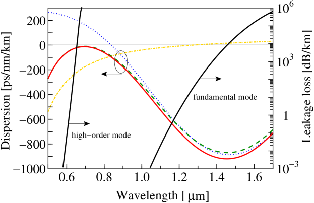
Figure 2 illustrates the typical dispersion properties of a photonic crystal fibre. The strongly negative material dispersion of silica below tend to make the total dispersion of standard fibres negative for , simply because of the very weak waveguide contribution . However, photonic crystal fibres are contrary to this since the composite air-silica cladding is seen to provide the guided mode with a strongly positive waveguide dispersion which tends to shift the zero-dispersion wavelength far below towards the visible. While the material dispersion is fixed the waveguide dispersion varies strongly in the phase-space spanned by and and in this way the competition between waveguide and material dispersion becomes a powerful mechanism in engineering the zero-dispersion wavelength.
3 A strand of silica in air — the ultimate limit?
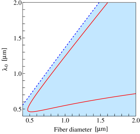
As mentioned in the introduction the zero-dispersion wavelength may be pushed to lower values by simply increasing the air hole diameter and decreasing the pitch. For this will to some extend effectively leave us with a single strand of silica surrounded by air. This limiting case has been emphasized previously in the literature and in Fig. 3 we reproduce the zero-dispersion wavelength results reported by Knight et al. [15]. Generally, the strand of silica will have either two dispersion zeros or none, with the exception of the special case where it only supports a single dispersion zero. PCFs turn out to follow the same overall pattern and the existence of two dispersion zeros turns out to have interesting applications in super-continuum generation [20].
The results in Fig. 3 leave promises for a zero-dispersion wavelength down to below 500 nm which will eventually also be the ultimate limit for silica based PCFs. However, as also indicated by the dashed line the large index contrast between air and silica in general prevents single-mode operation at the zero-dispersion wavelength. In the following we will study to which degree the photonic crystal cladding concept of PCFs can be used to circumvent this problem.
4 Photonic crystal cladding as a modal sieve
As demonstrated already by Birks et al. [13] the photonic crystal cladding of a PCF acts as modal sieve which may prevent localization of high-order modes to the core region. This so-called endlessly single-mode property has later been studied in great detail [14, 21, 22, 23] and it was recently argued that the endlessly single-mode phenomena is a pure geometrical effect and that the PCF is endlessly single mode for irrespectively of the fibre material refractive index [24]. The photonic crystal cladding thus serves to limit the number of guided modes and at the same time the guided modes will to some extend inherit the chromatic dispersion properties observed for the strand of silica in air [15].
The problem of zero-dispersion wavelength versus pitch has previously been studied for PCFs with an infinite photonic crystal cladding [19] demonstrating curves qualitatively resembling the curve in Fig. 3. Here, we extend that work to PCFs with a photonic crystal cladding of finite spatial extent. In particular, we study the effect of a varying number of rings of air holes surrounding the core region. We also study the cut-off and leakage properties to explore the possibility for a single-mode PCF with a zero-dispersion wavelength in the visible.
Our numerical solutions of the wave equation, Eq. (1), are based on a finite-element approach which is described in detail in Ref. [25]. For the calculation of the cut-off wavelength and the leakage loss we refer to Refs. [26, 27] and references therein.
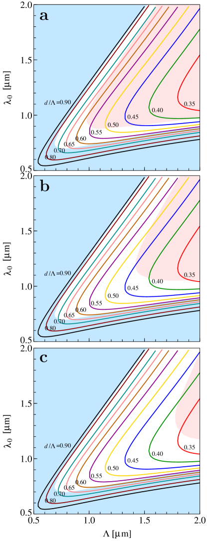
The results of extensive numerical simulations are summarized in Fig. 4. First of all we notice that the zero-dispersion wavelength versus pitch has a curve-shape qualitatively resembling the result in Fig. 3 for a strand of silica in air. Furthermore, we see that the number of rings of air holes has little influence on the zero-dispersion wavelength. In particular, the results for are in full quantitative agreement with those reported in Ref. [19]. On the other hand, the spatial extent of the photonic crystal cladding is as expected seen to have a huge impact on the leakage loss [28, 27] as seen from the red shading indicating the region with a leakage loss exceeding 0.1 dB/km. Furthermore, has as expected little effect on the cut-off wavelength since the cut-off and the modal sieving is governed by the width () of the silica regions between the air holes [24] rather than the spatial extent of the photonic crystal cladding.
Finally, we note that by choosing we may realize a PCF with a single zero-dispersion wavelength down to nm with the fibre being single-mode for longer wavelengths. We believe this to be the ultimate limit for silica-based PCFs having a photonic crystal cladding comprising a triangular arrangement of circular air holes. Such results have been demonstrated experimentally by e.g. Knight et al. [15]. In practice, the limit might be pushed slightly further toward the visible since real PCFs tend to have a slightly shorter cut-off wavelength compared to the expectations based on the ideal fibre structure [23]. Most likely, this tendency originates in the presence of scattering loss in real fibres which also acts in suppressing the high-order modes even though they are weakly guided by the photonic crystal cladding. In order to push the zero-dispersion wavelength further into the visible one would have to tolerate guidance of high-order modes or alternatively employ somewhat more complicated designs involving a varying air-hole diameter throughout the cladding [29].
5 Conclusion
In conclusion we have studied the zero-dispersion wavelength in silica based photonic crystal fibres with special emphasis on the interplay with the cut-off wavelength and leakage loss. In the large parameter space spanned by the air-hole diameter and the pitch we have identified the values facilitating the shortest possible zero-dispersion wavelength ( nm) while the fibre is still single-mode for longer wavelengths.
We believe that our -maps are an important input for the efforts in designing nonlinear photonic crystal fibres with still shorter zero-dispersion wavelengths for super-continuum generation in the visible.
6 Acknowledgments
N. A . M. acknowledges discussions with J. Lægsgaard as well as the collaboration on the zero-dispersion results in Ref. [19] which strongly stimulated the present work.
References
- [1] Russell P S J 2003 Science 299 358 – 362
- [2] Knight J C 2003 Nature 424 847 – 851
- [3] Mollenauer L F 2003 Science 302 996 – 997
- [4] Hansen K P 2005 Journal of Optical and Fiber Communications Reports 2 226 – 254 [doi: 10.1007/s10297-004-0021-1]
- [5] Zheltikov A M 2006 J. Opt. A: Pure Appl. Opt. 8 S47 – S72
- [6] Zheltikov A M 2006 Appl. Phys. B-Lasers Opt. 84 69 – 74
- [7] Ranka J K, Windeler R S and Stentz A J 2000 Opt. Lett. 25 25 – 27
- [8] Herrmann J, Griebner U, Zhavoronkov N, Husakou A, Nickel D, Knight J C, Wadsworth W J, Russell P S J and Korn G 2002 Phys. Rev. Lett. 88 173901
- [9] Jones D J, Diddams S A, Ranka J K, Stentz A, Windeler R S, Hall J L and Cundiff S T 2000 Science 288 635 – 639
- [10] Udem T, Holzwarth R and Hänsch T W 2002 Nature 416 233 – 237
- [11] Hartl I, Li X D, Chudoba C, Ghanta R K, Ko T H, Fujimoto J G, Ranka J K and Windeler R S 2001 Opt. Lett. 26 608 – 610
- [12] Knight J C, Birks T A, Russell P S J and Atkin D M 1996 Opt. Lett. 21 1547 – 1549
- [13] Birks T A, Knight J C and Russell P S J 1997 Opt. Lett. 22 961 – 963
- [14] Mortensen N A 2002 Opt. Express 10 341 – 348
- [15] Knight J C, Arriaga J, Birks T A, Ortigosa-Blanch A, Wadsworth W J and Russell P S J 2000 IEEE Phot. Technol. Lett. 12 807 – 809
- [16] Skryabin D V, Luan F, Knight J C and Russell P S J 2003 Science 301 1705 – 1708
- [17] Ferrando A, Silvestre E, Miret J J and Andres P 2000 Opt. Lett. 25 790 – 792
- [18] Lægsgaard J, Bjarklev A and Libori S E B 2003 J. Opt. Soc. Am. B 20 443 – 448
- [19] Lægsgaard J, Mortensen N A and Bjarklev A 2003 J. Opt. Soc. Am. B 20 2037 – 2045
- [20] Andersen T V, Hilligsøe K M, Nielsen C K, Thøgersen J, Hansen K P, Keiding S R and Larsen J J 2004 Opt. Express 12 4113 – 4122
- [21] Kuhlmey B T, McPhedran R C and de Sterke C M 2002 Opt. Lett. 27 1684 – 1686
- [22] Mortensen N A, Folkenberg J R, Nielsen M D and Hansen K P 2003 Opt. Lett. 28 1879 – 1881
- [23] Folkenberg J R, Mortensen N A, Hansen K P, Hansen T P, Simonsen H R and Jakobsen C 2003 Opt. Lett. 28 1882 – 1884
- [24] Mortensen N A 2005 Opt. Lett. 30 1455 – 1457
- [25] Koshiba M 2002 IEICE Trans. Electron. 85-C 881 – 888
- [26] Saitoh K, Tsuchida Y, Koshiba M and Mortensen N A 2005 Opt. Express 13 10833 – 10839
- [27] Koshiba M and Saitoh K 2005 Opt. Commun. 253 95 – 98
- [28] White T P, McPhedran R C, de Sterke C M, Botten L C and Steel M J 2001 Opt. Lett. 26 1660 – 1662
- [29] Jacobsen R S, Lægsgaard J, Bjarklev A and Hougaard K 2004 J. Opt. A: Pure Appl. Opt. 6 604 – 607