Demonstration of a moving guide based atom interferometer for rotation sensing
Abstract
We demonstrate area-enclosing atom interferometry based on a moving guide. Light pulses along the free propagation direction of a magnetic guide are applied to split and recombine the confined atomic matter-wave, while the atoms are translated back and forth along a second direction in 50 ms. The interferometer is estimated to resolve ten times the earth rotation rate per interferometry cycle. We demonstrate a “folded figure 8” interfering configuration for creating a compact, large-area atom gyroscope with multiple-turn interfering paths.
pacs:
39.20+q 03.75.dgI
In a Sagnac interferometry based gyroscope, a rotation with an angular velocity induces a shift of the interference fringe by the Sagnac phase , with the total mass of the interfering particle, the reduced Planck constant, and the area enclosed by the interfering paths projected along the rotation axis. Due to the large total mass, the Sagnac phase for atoms with the same area is typically times larger than it is for visible photons, which makes the atomic matter-wave gyroscope a promising candidate Clauser88 ; Gustavson97 to replace laser gyroscopes RinglaserReview to deliver unprecedented rotational sensitivities, with applications expected in long-distance inertial navigation, in geophysics research, and potentially in testing fundamental theories such as to measure geodesic and frame-dragging effects Clauser88 .
Existing atom gyroscopes use diffractive optics to manipulate atomic beams. In a typical 3-grating setup Gustavson97 , the area enclosed by the interfering paths can be expressed as , with the recoil velocity associated with the grating diffraction, the atomic beam velocity, and the time during which the atoms are successively interrogated by the three gratings. For example, the state-of-the-art atom gyroscope developed in the Kasevich group Gustavson2000 uses cesium atomic beams with an enclosed-area of mm2, based on an apparatus that is m long. Further increasing the area of atomic gyroscopes would improve their rotational sensitivity. However, atom gyroscopes need to be as compact as possible to suppress phase shifts due to stray fields as well as those due to mechanical vibrations, and a longer apparatus would limit the applications of the gyroscope. Recent interferometry techniques have been developed with slow atoms in parabolic trajectories SixAxis06 . However, a significant improvement of the sensing area in fountain geometry requires a tall atomic fountain and thus a large apparatus.
An obvious solution to fulfill the contradictory requirements of being compact and having a large sensing area is to let the two interfering paths circulate around a small physical area multiple times. To suppress any phase shift due to static perturbations, the paths may be chosen to be reciprocal, with one path following the time-reversal path of the other. A multiple-turn reciprocal interference configuration may be achievable using atomic guiding potentials. Recent research efforts have realized atomic wave-guide potentials in closed loops rings . However, interferometry with these devices has not been demonstrated. One of the technical challenges of this approach stems from the dispersive coupling of motion between the confining direction and the guide direction in curved atomic wave-guides betatron06 , usually large even in the adiabatic limit. Recently the interference of a propagating Bose-Einstein condensate was demonstrated to enclose an area following a “Y” splitting scheme chiplongcoherence ; however, it is unclear how to use the scheme to enclose a large area in multiple-turn reciprocal geometry.
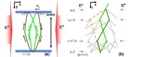
Instead of transporting atoms with curved wave-guides, we demonstrate an area-enclosing guided atom interferometer in a “folded figure 8” configuration based on a straight guide WangMichelson05 that moves. In particular, a two-dimensional interfering path of guided atoms is created by a pulsed optical standing wave field along combined with a guiding potential oscillating along (Fig. 1a). A 4-pulse de-Broglie wave interferometry scheme (Fig. 1b) TLCahn97 ; mythesis is applied to create an effectively-reciprocal interfering loop that encloses an area up to mm2 with stable phase readouts. We argue that the scheme demonstrated in this work can be extended to a practical large-area guided atom gyroscope with multiple-turn reciprocal paths.
We consider the schematic setup in Fig. 1. Atoms are confined in a guiding potential oriented to , the direction along which the guiding potential is invariant. An optical standing wave field composed of traveling light and is aligned parallel to WangMichelson05 . Standing wave pulses split and recombine the atom wavepackets along by transferring photon recoil momentum to atoms. When atoms are transported along the direction , the interfering paths enclose the area in the plane. In particular, as represented by the recoil diagrams shown by the thick solid lines in Fig. 1a, b, a nearly reciprocal interfering loop can be created by setting the guide velocity while the atom wavepackets are split at time and redirected at time , . Pairs of wavepackets meet at time , creating a “folded figure 8” loop in the x-y diagram and a “figure 8” loop in the x-t diagram. The area enclosed by the loop is , where is the wavepacket splitting velocity due to photon recoils and is the maximum translation distance along . Since the atoms almost return to the initial position at time , the sequence may be repeated times; each time the guide passes the half distance the two interfering paths are deflected by an additional standing wave pulse, resulting in multiple turn interfering paths. Precise reciprocity of the interfering paths can be achieved with atoms starting with zero velocity. With non-zero initial velocity (Fig. 1a), effective reciprocity is retained that suppresses the interferometry phase shifts due to potential variations at the length scale with .
In this demonstration, a 4-pulse de-Broglie wave interferometry scheme (Fig. 1b) gratingechoOrigin ; TLCahn97 is applied to address most of the atoms in our 25 atomic sample. We use short standing wave pulses (300 ns width) as thin phase gratings, that diffract atoms to multiple diffraction orders weighted by the amplitude . Here is the standing wave pulse area and is the order Bessel function TLCahn97 . Pairs of paths interfere and create an atomic density grating at time , which is probed by monitoring the Bragg scattering of a probe light from into mode mythesis . The two requirements for any two interfering paths to contribute to the Bragg backscattering of a probe light (grating echo) are: 1) they meet at time to form a loop, and 2) at time their relative velocities should be twice the atomic recoil velocity mm/sec. We classify these loops according to the relative displacements between each pair of paths. In addition to the “figure 8” loop in Fig. 1b that corresponds to the “folded figure 8” loop in Fig. 1a, other interfering loops also contribute, such as the “trapezoid” loop in Fig. 1b. The final interferences are composed of the contributions from all these loops. It can be shown that the contributions from the “figure 8” and the “trapezoid” loops are weighted by and respectively mythesis , while other loops contribute negligibly for standing wave pulse area . The reciprocity of the figure 8 loop ensures a zero differential phase shift between the two paths in the presence of a linear potential along , and suppresses the dephasing effects due to nonlinear potential variations. This is in contrast to the trapezoid loop that acquires a phase shift of due to an acceleration force ( the wave-vector of the light field) and dephases quickly in a nonlinear potential. The reciprocity of the “figure 8” loop is confirmed experimentally by analyzing the readouts due to the “trapezoid” loop and the “figure 8” loop.
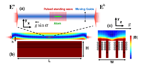
In what follows, we briefly summarize our experimental apparatus, detailed in mythesis . The layout of the experimental setup is described in Fig. 2. Four 200 mm 100 mm 1.5 mm permalloy foils, separated by 6.35, 12.7 and 6.35 mm, are poled in alternating directions (Fig. 2b, c) to generate a quadruple field as the guiding potential. Close to the center of the foils, the quadruple field can be approximately described by . A wave-guide operation distance of mm = 200 mm is chosen to minimize the edge effects. With the wave-guide operating at a field gradient of =70 G/cm, varies about 10 mG over a centimeter along , likely due to the foil-surface inhomogeneities. Approximately laser-cooled 87Rb atoms in their ground state hyperfine level are loaded into this magnetic guide resulting in a cylindrically-shaped atom sample 1 cm long and 170 wide. The standing wave is formed by two counter-propagating laser beams and (120 MHz to the blue side of the F=1 - F′=2 D2 transition) with diameters of 1.6 mm. A heterodyned detection of the Bragg scattering is applied to retrieve both the amplitude and the phase of the atomic fringe TLCahn97 . Precise alignment of the standing wave k-vector parallel to the free-propagation direction of the guide is required to decouple the wave-guide confinement from the interferometry phase readouts mythesis . To ensure parallelism, the relative angle between the standing wave and the wave-guide is minimized with two rotation stages (with the rotation axis along and in Fig. 2) at a precision better than mrad by minimizing the confinement-induced interferometry dephasing GuideTalbot05 .
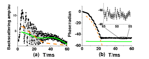
To illustrate the interference and decay of different interfering loops in Fig. 1b, we first discuss interferometry output with atoms in the stationary guide that are shown in Fig. 3. Given the 300 ns standing wave pulse duration, we set the pulse area to be for the second and the third pulse by adjusting the intensity of the pulses. In repeated experiments, the amplitude and phase of the Bragg scattering signals were recorded with different total interrogation time , which is incremented from ms to ms in steps of 132.6 s. The oscillatory amplitude/phase readout in Fig. 3 is due to the beat between the “figure 8” loop (thick solid line) and the “trapezoid” loop ( thick dashed line) in Fig. 1b. With a numerical routine to separate the fast oscillating parts from the slowly varying parts, the oscillatory interferometry amplitude and phases are decomposed to the solid and dashed curves in Fig. 3, which represent the contributions from the “figure 8” and the “trapezoid” loops in Fig. 1b respectively. The acceleration force is due to a small gravity component along the direction with (In Fig. 2 the gravity is along and mrad). We extract the acceleration constant mm/ from the dashed curve in Fig. 3b, which is found to agree with those from independent measurements using 3-pulse interferometers TLCahn97 . The solid curve in Fig. 3a has a smaller initial amplitude but a slower decay, so that the two curves cross at ms. Correspondingly, the phase readout in Fig. 3 approximately follows the parabolic curve for ms but is locked to a constant value for ms. The slow dephasing of the “figure 8” loop is attributed to the approximate reciprocity between the two interfering paths (Fig. 1b). The results in Fig. 3 demonstrate that in the presence of multi-loop interference in this experiment, an independent observation of the “figure 8” loop is nevertheless possible for ms due to its relatively long coherence time.
We now discuss the moving guide interferometer. To translate the atomic sample along , we pulse a 50ms-period sinusoidal current through the coils that magnetize the inner two foils of the 4-foil (Fig. 2c). The resulting motion of the guided atomic sample in the plane is monitored with the absorption images probed by (Fig. 2a, b). For the absorption image, the frequency of is tuned to resonance before the laser is coupled into a fiber. The fiber coupling ensures that the spatial mode of is consistent for both the absorption image and the standing wave formation. A sequence of absorption images taken in repeated experiments is presented in Fig. 4a. The motion of atoms follows a “cosine” trace fairly well with an amplitude of mm.
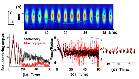
To realize area-enclosing interferometry, we repeat the 4-pulse interferometry measurements with the same current settings that induced the atomic motion shown in Fig. 4a. Typical interferometry amplitude and phase readouts are plotted in Fig. 4 in red, together with comparison data from another stationary guide experiment plotted in black. Here a standing wave pulse area of is chosen to maximize the interference due to the “figure 8” loop. A consequence is the more constant phase readout for the black plots in Fig. 4c, compared with those shown in Fig. 3b. In contrast to the stationary guide case, the amplitude of the moving guide interferometer signal (red plots) almost vanishes in the time window of from 25 ms to 35 ms because the atoms are at the very outer edge of the optical fields when the probing pulse is fired, resulting in vanishing backscattering signals and thus random phase readouts (Fig. 4c). For ms, the atomic sample returns back to within the mm diameter of the optical fields. The backscattered signal revives and the phase readout matches those in the stationary guide case (Fig. 4d). Similar to Fig. 3b, the constant and repeatable phase readouts in Fig. 4d are due to the approximate reciprocity of the “figure 8” loop, which in the spatial-domain becomes the “folded figure 8” loop in Fig. 1a. For ms, the interferometer encloses an area of 0.18 mm2 exp:foot1 . A rotation rate of 1 mrad/sec should induce a Sagnac phase of that shifts the red plot in Fig. 4 d.
The small phase offset observed in Fig. 4d between the readouts from a stationary guide and the moving guide is repeatable before any realignments. The offset is due to the guiding potential variation along . In this experiment, the moving guide potential does not precisely follow a sinusoidal trace, and collective atomic oscillations in the moving guide are expected since the wave-guide confinement is relatively loose. The non-reciprocity leads to imperfect cancelation of the phase shifts before and after (Fig. 1) that results in the phase offset in Fig. 4d. The imperfection is not precisely repeatable in each experimental trial, resulting in a standard deviation of the phase readout rad exp:foot2 . A smoother and more precisely controlled guiding potential would help to suppress the phase error as well as the dephasing effects that have limited the interrogation time of 50 ms in this experiment. By reducing the wavepacket separations using a different interferometry scheme, we have achieved up to 1 coherence time with guided atoms longcoherence .
The mm2 enclosed area is much smaller than in Gustavson2000 . However, orders of magnitude improvements in the sensing area are expected with larger guide translation distances, a more efficient beamsplitting scheme, and longer interrogation time mythesis . To increase the wave-guide translation distance, a multi-wire 1D conveyer belt on an atom chip WangMichelson05 may be constructed. The localized atomic sample in the wave-guide should facilitate a high-efficiency multiple-recoil beamsplitting doublepulse05 where the light intensity control is important. We consider a 87Rb atomic sample at sub-recoil temperatures so that multi-photon beam splitting techniques can be applied giving efficient momentum splittings doublepulse05 . If the wave-guide were oscillated 5 cm back and forth 5 times accompanied by 10 appropriately timed Bragg pulses, the interferometer on a centimeter-scale device would enclose an area greater than 1000 mm2 in a second. If we consider a shot-noise limited phase resolution, the resulting on-chip atom gyroscope would have a rotational sensitivity of rad/ comparable to Gustavson2000 , even with only atoms per experimental cycle. Parallel operation of multiple guided atom gyroscopes may further boost the measurement bandwidth and sensitivity.
In conclusion, we have demonstrated a moving-guide based atom interferometer that encloses an area of mm2 and has stable phase readout for rotation sensing. We have demonstrated a “folded figure 8” interferometry configuration whose reciprocity partly suppresses matterwave dephasing due to guiding potential variations. The “folded figure 8” configuration should be sensitive to rotation but extremely insensitive to linear acceleration. The scheme may be extended to enable sensitive rotation measurement with a multiple-turn atomic matterwave gyroscope in a compact device.
This work also demonstrates coherent transportation of matter-waves using magnetic-dipole forces. The moving guide may allow a light pulse atom interferometer to interact with a distant object where the optical path is restricted, such as to sense the light shift of a micro-cavity or a surface potential.
Acknowledgements.
This work is supported by MURI and DARPA from DOD, NSF, ONR and U.S. Department of the Army, Agreement Number W911NF-04-1-0032, and by the Charles Stark Draper Laboratory. We thank the referees for their suggestions on the earlier version of this article.References
- (1) J. F. Clauser, Physica B, 151, 262 (1988).
- (2) F. Riehle et al., Phys. Rev. Lett. 67, 177 (1991). A. Lenef et al., Phys. Rev. Lett. 78, 760 (1997). T. L. Gustavson et al., Phys. Rev. Lett. 78, 2046 (1997).
- (3) G. E. Stedman, Rep. Prog. Phys. 60, 615 (1997).
- (4) T. L. Gustavson et al., Classical Quantum Gravity 17, 2385 (2000). D. S. Durfee et al., Phys. Rev. Lett. 97, 240801 (2006).
- (5) B. Canuel et al., Phys. Rev. Lett. 97, 10402 (2006).
- (6) J. Sauer et al., Phys. Rev. Lett. 87, 270401 (2001). S. Wu et al., Phys. Rev. A 70, 013409 (2004). S. Gupta et al., Phys. Rev. Lett. 95, 143201 (2005).
- (7) K. W. Murch et al., Phys. Rev. Lett. 96, 013202 (2006).
- (8) G.-B. Jo et al., Phys. Rev. Lett. 98, 030407 (2007).
- (9) Y.-J. Wang et al., Phys. Rev. Lett. 94, 090405 (2005).
- (10) S. B. Cahn et al., Phys. Rev. Lett. 79, 784 (1997).
- (11) S. Wu, Ph. D. Thesis, Harvard Univ. (2007).
- (12) T. W. Mossberg et al., Phys. Rev. Lett. 43, 851 (1979).
- (13) S. Wu et al., Eur. Phys. J. D 35, 111 (2005).
- (14) Area up to mm2 was enclosed with ms.
- (15) The phase noise due to imperfect suppression of the “trapezoid” loop is 0.2 rad here. A method to completely supress the loop was suggested by B. et al. in Phys. Rev. A 74, 023615 (2006).
- (16) E. J. Su et al., physics/0701018.
- (17) S. Wu et al., Phys. Rev. A 71, 43602 (2005).