Broadband diffraction management and self-collimation of white light in photonic lattices
Abstract
We suggest a novel type of photonic structures where the strength of diffraction can be managed in a very broad frequency range. We introduce optimized arrays of curved waveguides where light beams experience wavelength-independent normal, anomalous, or zero diffraction. Our results suggest novel opportunities for efficient self-collimation, focusing, and reshaping of beams produced by white-light and super-continuum sources. We also show how to manipulate light patterns through multicolor Talbot effect, which is possible neither in free space nor in conventional photonic lattices.
pacs:
42.25.Fx, 42.82.Et, 61.12.BtIt is known that periodic photonic structures can be employed to engineer and control the fundamental properties of light propagation Joannopoulos:1995:PhotonicCrystals ; Russell:1995-585:ConfinedElectrons . In particular, the beam refraction and diffraction can be modified dramatically, resulting in many unusual phenomena. For example, a beam can experience negative refraction in the direction opposite to normal at the interface with a photonic crystal Russell:1995-585:ConfinedElectrons ; Notomi:2000-10696:PRB ; Cubukcu:2003-604:NAT ; Rosberg:2005-2293:OL . Additionally, the natural tendency of beams to broaden during propagation can be controlled through diffraction management Eisenberg:2000-1863:PRL . Diffraction can be eliminated in periodic structures leading to self-collimation effect where the average beam width does not change over hundreds of free-space diffraction lengths Rakich:2006-93:NAMT . On the other hand, diffraction can be made negative allowing for focusing of diverging beams Pertsch:2002-93901:PRL and imaging of objects with sub-wavelength resolution Parimi:2003-404:NAT ; Lu:2005-153901:PRL .
The physics of periodic photonic structures is governed by scattering of waves from modulations of the refractive index and their subsequent interference. This is a resonant process, which is sensitive to both the frequency and propagation angle. Strong dependence of the beam refraction on the optical wavelength known as superprism effect was observed in photonic crystals Kosaka:1999-2032:JLT . Spatial beam diffraction also depends on the wavelength, and it was found in recent experiments Rakich:2006-93:NAMT ; Longhi:2006-243901:PRL that the effect of beam self-collimation is restricted to a spectral range of less than 10% of the central frequency. Such a strong dependence of the spatial beam dynamics on wavelength can be used for multiplexing and demultiplexing of signals in optical communication networks Wu:2002-915:IQE ; Wan:2005-353:OC . However, it remains an open question whether photonic structures can be used to perform spatial steering and shaping of beams emitted by white-light sources, such as light with supercontinuum frequency spectrum generated in photonic-crystal fibers and fiber tapers Ranka:2000-25:OL ; Wadsworth:2002-2148:JOSB .
In this Letter, we suggest a novel type of periodic photonic structures designed for wavelength-independent diffraction management in a very broad frequency range, covering a spectral range up to 50% of the central frequency. We introduce the optimized periodic structures where multicolor beams experience constant normal, anomalous, or zero diffraction. This opens up novel opportunities for efficient self-collimation, focusing, and shaping of white-light beams. For example, in such optimized structures it becomes possible to manipulate white-light patterns through multicolor Talbot effect, which otherwise is not feasible in free space or in conventional photonic lattices.
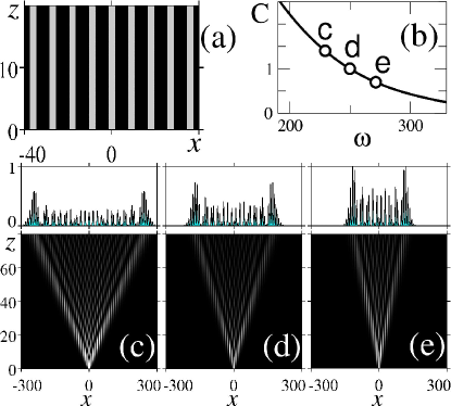
We study propagation of beams emitted by a continuous white-light source in a periodic array of coupled optical waveguides [see Fig. 1(a)], where the waveguide axes are also periodically curved in the propagation direction [see examples in Figs. 2(a) and 3(a)]. In the linear regime, the overall beam dynamics is defined by independent evolution of complex beam envelopes ) at individual frequency components governed by the normalized paraxial equations,
| (1) |
where and are the transverse and propagation coordinates normalized to the characteristic values and , respectively, is the vacuum wavelength, is the speed of light, is the average refractive index of the medium, is the refractive index modulated with the period in the transverse direction, and defines the longitudinal bending profile of the waveguide axis with the period . When the tilt of beams and waveguides at the input facet is less than the Bragg angle at each wavelength, the beam propagation is primarily characterized by coupling between the fundamental modes of the waveguides, and can be described by the tight-binding equations taking into account the periodic waveguide bending Longhi:2005-2137:OL ; Longhi:2006-243901:PRL ,
| (2) |
where are the mode amplitudes, is the waveguide number, is the dimensionless frequency, and the dots stand for the derivatives. Coefficient defines a coupling strength between the neighboring waveguides, and it characterizes diffraction in a straight waveguide array with Jones:1965-261:JOS ; Somekh:1973-46:APL . The coupling coefficient decreases at higher frequencies Iwanow:2005-53902:PRL and accordingly the beam broadening is substantially weaker at shorter wavelengths, see Figs. 1(b-e).
We consider symmetric profiles of the waveguide bending such that for a given coordinate shift , where function is symmetric, . Then, after a full bending period () the beam diffraction is the same as in a straight waveguide array with the effective coupling coefficient Longhi:2005-2137:OL ; Longhi:2006-243901:PRL
| (3) |
According to Eq. (3), diffraction of multicolor beams is defined by an interplay of bending-induced dispersion and frequency dependence of the coupling coefficient in a straight waveguide array. We suggest that spatial evolution of all frequency components can be synchronized allowing for shaping and steering of multi-color beams, when effective coupling remains constant around the central frequency ,
| (4) |
and we demonstrate below that this condition can be satisfied by introducing special bending profiles.
First, we demonstrate the possibility for self-collimation of white-light beams, where all the wavelength components remain localized despite a nontrivial evolution in the photonic structure. Self-collimation regime is realized when the diffraction is suppressed and the effective coupling coefficient vanishes, . This effect was previously observed for monochromatic beams in arrays with zigzag Eisenberg:2000-1863:PRL or sinusoidal Longhi:2006-243901:PRL bending profiles, however in such structures the condition of zero coupling cannot be satisfied simultaneously with Eq. (4), resulting in strong beam diffraction under frequency detuning by several percent Longhi:2006-243901:PRL . We find that broadband diffraction management becomes possible in hybrid structures with a periodic bending profile that consists of alternating segments [see example in Fig. 2(a)], for , for , and for . Effective coupling in the hybrid structure can be calculated analytically, , where is the Bessel function of the first kind of the order , , and .
We select a class of symmetric profiles of the waveguide bending to avoid asymmetric beam distortion due to higher-order effects such as third-order diffraction. Additionally, the waveguides are not tilted at the input, i.e. , in order to suppress excitation of higher-order photonic bands by incident beams inclined by less than the Bragg angle. The effect of Zener tunneling to higher bands Zener:1934-523:RAR ; Trompeter:2006-23901:PRL and associated scattering losses can be suppressed irrespective of the waveguide tilt inside the photonic structure by selecting sufficiently slow modulation to minimize the curvature and thereby achieve adiabatic beam shaping.
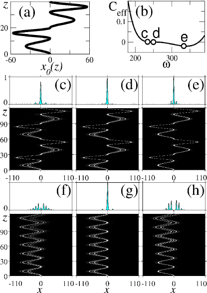
In order to realize broadband self-collimation, we choose the structure parameters such that and are the first and the second roots of equation . Then, the self-collimation condition is exactly fulfilled at the central frequency , , and simultaneously the condition of frequency-independent coupling in Eq. (4) is satisfied for the following modulation parameters, , , and . As a result, we obtain an extremely flat coupling curve shown in Fig. 2(b) where the point ‘d’ corresponds to the central frequency. In this hybrid structure not only the first derivative vanishes according to Eq. (4), but the second derivative vanishes as well, . As a result, the effective coupling remains close to zero in a very broad spectral region of up to 50% of the central frequency. We note that the modulation period is a free parameter, and it can always be chosen sufficiently large to avoid scattering losses due to waveguide bending since the maximum waveguide curvature is inversely proportional to the period, . Although the beam evolution inside the array does depend on the wavelength, the incident beam profile is exactly restored after a full modulation period, see examples in Figs. 2(c-e). Self-collimation is preserved even at the red spectral edge, where coupling length is the shortest and discrete diffraction in the straight array is the strongest [cf. Fig. 2(c) and Fig. 1(c)]. The hybrid structure provides a dramatic improvement in the bandwidth for self-collimation effect compared to the array with a simple sinusoidal modulation, where beams exhibit diffraction under small frequency detuning, see Figs. 2(f-h).
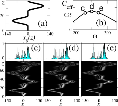
We now analyze the conditions for frequency-independent normal or anomalous diffraction that may find applications for reshaping of multicolor beams. In order to reduce the device dimensions, it is desirable to increase the absolute value of the effective coupling and simultaneously satisfy Eq. (4) to achieve broadband diffraction management. We find that Eq. (4) can be satisfied even in the simplest two-segment hybrid structure with and . Here a set of possible parameter values is determined form the relation , where and characterize dispersion of coupling in a straight array. It is possible to obtain both normal and anomalous diffraction regimes for normally incident beams, corresponding to positive and negative effective couplings depending on the chosen value of . For example, for the waveguide array shown in Fig. 1, at the central frequency [corresponding wavelength is ] coupling parameters are and . Then, constant positive coupling around the central frequency is realized for and constant negative coupling for .
We perform a comprehensive analytical and numerical analysis, and find that a hybrid structure with bending profile consisting of one straight (i.e ) and one sinusoidal segment can provide considerably improved performance if , where value is found from the equation . Under such conditions, larger values of positive effective coupling can be obtained in a hybrid structure with , , . In this structure, the effective coupling at central frequency is .
Example of a hybrid structure which provides strong wavelength-independent diffraction is shown in Fig. 3(a), and the corresponding effective coupling is plotted in Fig. 3(b). The output diffraction profiles in this optimized structure are very similar in a broad spectral region, see examples for three wavelengths in Figs. 3(c-e). We note that the outputs at these wavelengths are substantially different after the same propagation length in the straight waveguide array, as shown in Figs. 1(c-e).
As one of the applications of the broadband diffraction management we consider a multicolor Talbot effect which allows to manipulate white-light patterns. The Talbot effect, when any periodical monochromatic light pattern reappears upon propagation at certain equally spaced distances, has been known since the famous discovery in 1836 Talbot:1836-401:RAR . It was recently shown that the Talbot effect is also possible in discrete systems for certain periodic input patterns Iwanow:2005-53902:PRL . For example, for the monochromatic periodic input pattern of the form , Talbot revivals take place at the distance , see Fig. 4(a).
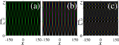
Period of the discrete Talbot effect in the waveguide array is inversely proportional to the coupling coefficient , which strongly depends on frequency, see Fig. 1(b). Therefore, for each specific frequency Talbot recurrences occur at different distances Iwanow:2005-53902:PRL , and periodic intensity revivals disappear for the multicolor input, see Fig. 4(b). Multicolor Talbot effect is also not possible in free space where revival period is proportional to frequency. Most remarkably, multicolor Talbot effect can be observed in optimized waveguide arrays with wavelength-independent diffraction, see Fig. 4(c). In this example, we use the shape of structure with constant positive diffraction shown in Fig. 3, and choose half of the bending period to be equal to the period of the Talbot recurrences for the corresponding effective coupling in this structure, . We note that the length of the straight segment is equal to the Talbot distance at central wavelength in the straight array, , which explains partial revivals at the end of the straight segments visible in Fig. 4(c).
In conclusion, we have introduced a novel class of photonic structures where diffraction can be engineered in a very broad frequency range. We have analyzed the optimized array of periodically curved waveguides where light beams experience wavelength-independent normal, anomalous, or zero diffraction, and predicted the multicolor Talbot effect which is not possible in free space and conventional waveguide arrays. Our results suggest novel opportunities for efficient self-collimation, focusing, and reshaping of beams produced by white-light and super-continuum sources.
References
- (1) J. D. Joannopoulos, R. D. Meade, and J. N. Winn, Photonic Crystals: Molding the Flow of Light (Princeton University Press, Princeton, 1995).
- (2) P. St. J. Russell, T. A. Birks, and F. D. Lloyd Lucas, “Photonic Bloch waves and photonic band gaps,” in Confined Electrons and Photons, E. Burstein and C. Weisbuch, eds., (Plenum, New York, 1995), pp. 585–633.
- (3) M. Notomi, Phys. Rev. B 62, 10696 (2000).
- (4) E. Cubukcu et al., Nature 423, 604 (2003).
- (5) C. R. Rosberg et al., Opt. Lett. 30, 2293 (2005).
- (6) H. S. Eisenberg et al., Phys. Rev. Lett. 85, 1863 (2000).
- (7) P. T. Rakich et al., Nature Materials 5, 93 (2006).
- (8) T. Pertsch et al., Phys. Rev. Lett. 88, 093901 (2002).
- (9) P. V. Parimi et al., Nature 426, 404 (2003).
- (10) Z. L. Lu et al., Phys. Rev. Lett. 95, 153901 (2005).
- (11) H. Kosaka et al., J. Lightwave Technol. 17, 2032 (1999).
- (12) S. Longhi et al., Phys. Rev. Lett. 96, 243901 (2006).
- (13) L. J. Wu et al., IEEE J. Quantum Electron. 38, 915 (2002).
- (14) J. Wan et al., Opt. Commun. 247, 353 (2005).
- (15) J. K. Ranka, R. S. Windeler, and A. J. Stentz, Opt. Lett. 25, 25 (2000).
- (16) W. J. Wadsworth et al., J. Opt. Soc. Am. B 19, 2148 (2002).
- (17) S. Longhi, Opt. Lett. 30, 2137 (2005).
- (18) A. L. Jones, J. Opt. Soc. Am. 55, 261 (1965).
- (19) S. Somekh et al., Appl. Phys. Lett. 22, 46 (1973).
- (20) R. Iwanow et al., Phys. Rev. Lett. 95, 053902 (2005).
- (21) C. Zener, Proc. R. Soc. London A 145, 523 (1934).
- (22) H. Trompeter et al., Phys. Rev. Lett. 96, 023901 (2006).
- (23) H. F. Talbot, Phil. Mag. 9, 401 (1836).