Multiple scattering and PXR: kinematical suppression of multiple scattering influence on PXR and dynamical shift of diffraction peaks

Konstantin Batrakov Institute for Nuclear Problems, Belarus State University.
Abstract

One feature of passing relativistic electron through a single crystal is emission of parametric X-ray radiation (PXR) due to diffraction on a crystallographic planes. As was shown in 1 , PXR and coherent bremsstrahlung (CBS) take place for non-relativistic (or slow relativistic) electrons too. In this case emission spectrum consists of number of peaks corresponding to crystal reflexes in background of incoherent bremsstrahlung. These peaks are distinguished only for thin crystals, because the influence of electron multiple scattering on radiation increases with the crystal thickness and, as a result, smoothes out peaks. Simulation of PXR and CBS emission and considering of multiple scattering influence on spectra are carried out in present work. The optimal geometry with suppressed influence of multiple scattering is considered. Optimal geometry corresponds to the following condition

cosψ=1/1+(βusinθ1βucosθ)2.𝜓11superscriptsubscript𝛽𝑢𝜃1subscript𝛽𝑢𝜃2\cos\psi=1/\sqrt{1+\left(\frac{\beta_{u}\sin\theta}{1-\beta_{u}\cos\theta}\right)^{2}}.

Here ψ𝜓\psi is inclination angle of electron velocity vector relative to the reciprocal lattice vector corresponding to the reflex under consideration. βu=u/csubscript𝛽𝑢𝑢𝑐\beta_{u}=u/c, where u𝑢u is average velocity of electron in beam , θ𝜃\theta is the angle between velocity and wave vector of emitted photon. Optimal geometry gives possibility to use more thick crystals for PXR generation. The dynamical shift of PXR peaks which is one more feature of multiple scattering influence is predicted and discussed.

I Introduction

PXR is the radiation from a charged particle due to the photon diffraction on the planes of a single crystal. It was shown both theoretically and experimentally and citation therein) that PXR from a relativistic electron (E50MeV𝐸50MeVE\geq 50~{}\mathrm{MeV}) led to very high spectral intensity within the narrow angular and spectral range (ΔθΔω/ω103similar-toΔ𝜃Δ𝜔𝜔similar-tosuperscript103\Delta\theta\sim\Delta\omega/\omega\sim 10^{-3}).

Work 1 discussed and explained diffraction peaks produced experimentally in 2 ; 3 ; 4 for non-relativistic electrons (E50÷100keVsimilar-to𝐸50100keVE\sim 50\div 100~{}\mathrm{keV}) on the basis of interference between PXR and CBS. But the non-relativistic electron beam passing through the crystal is under the strong action of Coulomb multiple scattering. It action is so great that the electron beam becomes completely isotropic after passing through the crystal with the thickness of order of several microns. So, the PXR and CBS is lost in the background of incoherent bremsstrahlung. For observation of PXR and CBS peaks the crystal must be sufficiently thin (0.1μmsimilar-toabsent0.1𝜇m\sim 0.1~{}\mu\textrm{m}).

In the present paper influence of multiple scattering on PXR and CBS peaks is studied. The features of PXR and CBS such as dynamical peak frequency shifts and kinematical suppression of multiple scattering are derived and discussed.

II Account of multiple scattering

Corresponding to Feranchuck 1 , the spectral-angular distribution of emitted quanta has form:

d2N𝐧ω(s)=e2ω4πc3𝐠|𝐯0𝐄gsem𝐞s𝐠𝐠𝐯0Ugem𝐯0𝐤𝐠(𝐠𝐯0)2Ug|2×\displaystyle d^{2}N_{\mathbf{n}\omega}^{(s)}=\frac{e^{2}\omega}{4\pi\hbar c^{3}}\sum_{\mathbf{g}}\left|\mathbf{v}_{0}\mathbf{E}_{g_{s}}-\frac{e}{m}\frac{\mathbf{e}_{s}\mathbf{g}}{\mathbf{g}\mathbf{v}_{0}}U_{g}-\frac{e}{m}\mathbf{v}_{0}\frac{\mathbf{k}\mathbf{g}}{(\mathbf{g}\mathbf{v}_{0})^{2}}U_{g}\right|^{2}\times
|exp[i((𝐤+𝐠)𝐯0ω)t]1(𝐤+𝐠)𝐯0ω|2dωdΩ.superscript𝑖𝐤𝐠subscript𝐯0𝜔𝑡1𝐤𝐠subscript𝐯0𝜔2𝑑𝜔𝑑Ω\displaystyle\left|\frac{\exp[i((\mathbf{k}+\mathbf{g})\mathbf{v}_{0}-\omega)t]-1}{(\mathbf{k}+\mathbf{g})\mathbf{v}_{0}-\omega}\right|^{2}d\omega d\Omega. (1)

Here 𝐄gs=χg(c2𝐤g(𝐠𝐞s)ω2𝐞s)/(kg2c2ω2)subscript𝐄subscript𝑔𝑠subscript𝜒𝑔superscript𝑐2subscript𝐤𝑔subscript𝐠𝐞𝑠superscript𝜔2subscript𝐞𝑠superscriptsubscript𝑘𝑔2superscript𝑐2superscript𝜔2\mathbf{E}_{g_{s}}=\chi_{g}\left(c^{2}\mathbf{k}_{g}(\mathbf{g}\mathbf{e}_{s})-\omega^{2}\mathbf{e}_{s}\right)/\left(k_{g}^{2}c^{2}-\omega^{2}\right),Ug=subscript𝑈𝑔absentU_{g}=, χgsubscript𝜒𝑔\chi_{g} is crystal polarizabilities, 𝐞ssubscript𝐞𝑠\mathbf{e}_{s} is photon polarization vector, 𝐠𝐠\mathbf{g} is reciprocal lattice vector, 𝐯0subscript𝐯0\mathbf{v}_{0} is electron velocity, e,m𝑒𝑚e,m are electron electrical charge and mass. t𝑡t is time of electron passing through the crystal, 𝐤𝐤\mathbf{k} and ω𝜔\omega are wave vector and frequency of emitted photons.
Electron beam under action of multiple scattering acquires velocity spread, therefore (1) should be averaged over this spread:

d2N𝐧ω(s)superscript𝑑2superscriptsubscript𝑁𝐧𝜔𝑠\displaystyle d^{2}N_{\mathbf{n}\omega}^{(s)} =\displaystyle= e2ω4πc3dφ02πdθ0θ0f(θ0)𝐠|𝐯0𝐄gsem𝐞s𝐠𝐠𝐯0Ugem𝐯0𝐤𝐠(𝐠𝐯0)2Ug|2×\displaystyle\frac{e^{2}\omega}{4\pi\hbar c^{3}}\int\frac{d\varphi_{0}}{2\pi}d\theta_{0}\theta_{0}f(\theta_{0})\sum_{\mathbf{g}}\left|\mathbf{v}_{0}\mathbf{E}_{g_{s}}-\frac{e}{m}\frac{\mathbf{e}_{s}\mathbf{g}}{\mathbf{g}\mathbf{v}_{0}}U_{g}-\frac{e}{m}\mathbf{v}_{0}\frac{\mathbf{k}\mathbf{g}}{(\mathbf{g}\mathbf{v}_{0})^{2}}U_{g}\right|^{2}\times (2)
|exp[i((𝐤+𝐠)𝐯0ω)t]1(𝐤+𝐠)𝐯0ω|2dωdΩ.superscript𝑖𝐤𝐠subscript𝐯0𝜔𝑡1𝐤𝐠subscript𝐯0𝜔2𝑑𝜔𝑑Ω\displaystyle\left|\frac{\exp[i((\mathbf{k}+\mathbf{g})\mathbf{v}_{0}-\omega)t]-1}{(\mathbf{k}+\mathbf{g})\mathbf{v}_{0}-\omega}\right|^{2}d\omega d\Omega.

In (2) f(θ0)𝑓subscript𝜃0f(\theta_{0}) is distribution function of electron beam (θ0subscript𝜃0\theta_{0} is angle relative to vector of average velocity). Distribution function will be used in gaussian form

f(θ0)=2exp{θ02θs2}θs2.𝑓subscript𝜃02superscriptsubscript𝜃02superscriptsubscript𝜃𝑠2superscriptsubscript𝜃𝑠2f(\theta_{0})=\frac{2\exp\left\{-\frac{\displaystyle\theta_{0}^{2}}{\displaystyle\theta_{s}^{2}}\right\}}{\theta_{s}^{2}}. (3)

In (3) θssubscript𝜃𝑠\theta_{s} is scattering angle the square of which equals to θs2=16πn0Z(Z+1)re2(E+1)2E2(E+2)2LKLesuperscriptsubscript𝜃𝑠216𝜋subscript𝑛0𝑍𝑍1superscriptsubscript𝑟𝑒2superscript𝐸12superscript𝐸2superscript𝐸22subscript𝐿𝐾subscript𝐿𝑒\theta_{s}^{2}=16\pi n_{0}Z(Z+1)r_{e}^{2}\frac{\displaystyle(E+1)^{2}}{\displaystyle E^{2}(E+2)^{2}}L_{K}L_{e}. Lesubscript𝐿𝑒L_{e} is an electron path in crystal 5 , Z𝑍Z is the crystal atom number, E=T/(mc2)𝐸𝑇𝑚superscript𝑐2E=T/(mc^{2}), T𝑇T is electron kinetic energy, Lksubscript𝐿𝑘L_{k} is Coulomb logarithm, n0subscript𝑛0n_{0} is atom density. Typical value of scattering angle for Si𝑆𝑖Si at path length 1μm1𝜇m1~{}\mu\mathrm{m} is θs0.4radsimilar-tosubscript𝜃𝑠0.4rad\theta_{s}\sim 0.4~{}\mathrm{rad}. In (2) angular dispersion is taken into account only. Energy dispersion and energy losses exerts significantly less influence on radiation at considered energies (electron energy losses on ionization in Si𝑆𝑖Si is of order of 100100100 eV at electron energy E=100𝐸100E=100 keV and crystal thickness 1μ1𝜇1~{}\mum).

Line width of electron spontaneous emission without accounting the multiple scattering can be estimated as Δω/ω1/(kLe)similar-toΔ𝜔𝜔1𝑘subscript𝐿𝑒\Delta\omega/\omega\sim 1/(kL_{e}) (if Lesubscript𝐿𝑒L_{e} is less than absorption length) and it gives Δω/ω102similar-toΔ𝜔𝜔superscript102\Delta\omega/\omega\sim 10^{-2} for crystal thickness 0.1μmsimilar-toabsent0.1𝜇m\sim 0.1~{}\mu\mathrm{m}. Therefore, scattering angle for crystal 0.1μmabsent0.1𝜇m\geq 0.1~{}\mu\mathrm{m} is greater than spontaneous emission line width. In this case we can use in (2) the following approximation

|exp[i((𝐤+𝐠)𝐯0ω)t]1(𝐤+𝐠)𝐯0ω|2=2πδ(ω(𝐤+𝐠)𝐯0)1exp{kz"L}kz"v0z,superscript𝑖𝐤𝐠subscript𝐯0𝜔𝑡1𝐤𝐠subscript𝐯0𝜔22𝜋𝛿𝜔𝐤𝐠subscript𝐯01superscriptsubscript𝑘𝑧"𝐿superscriptsubscript𝑘𝑧"subscript𝑣0𝑧\left|\frac{\exp[i((\mathbf{k}+\mathbf{g})\mathbf{v}_{0}-\omega)t]-1}{(\mathbf{k}+\mathbf{g})\mathbf{v}_{0}-\omega}\right|^{2}=2\pi\delta\left(\omega-(\mathbf{k}+\mathbf{g})\mathbf{v}_{0}\right)\frac{1-\exp\left\{-k_{z}^{"}L\right\}}{k_{z}^{"}v_{0z}}, (4)

where kz"superscriptsubscript𝑘𝑧"k_{z}^{"} is imaginary part of wave vector component kzsubscript𝑘𝑧k_{z}, L𝐿L is crystal thickness. Integrating (2) over θ0subscript𝜃0\theta_{0} gives

d2Nnω(s)=e21exp{kz"L}4πc3kz"uzπθs2g|A|2dφ01[tan(θg)cos(φφ0)]22Δg×\displaystyle d^{2}N_{\vec{n}\omega}^{(s)}=\frac{e^{2}1-\exp\left\{-k_{z}^{"}L\right\}}{4\pi\hbar c^{3}k_{z}^{"}u_{z}\pi\theta_{s}^{2}}\sum_{\vec{g}}\left|A\right|^{2}\int^{{}^{\prime}}d\varphi_{0}\frac{1}{\sqrt{\left[\ \tan(\theta_{g})\cos(\varphi-\varphi_{0})\right]^{2}-2\Delta_{g}}}\times
×{(tan(θg)cos(φφ0)+[tan(θg)cos(φφ0)]22Δg)\displaystyle\times\left\{\left(\tan(\theta_{g})\cos(\varphi-\varphi_{0})+\sqrt{\left[\ \tan(\theta_{g})\cos(\varphi-\varphi_{0})\right]^{2}-2\Delta_{g}}\right)\right.
exp[(tan(θg)cos(φφ0)+[tan(θg)cos(φφ0)]22Δg)2/θs2]+limit-fromsuperscriptsubscript𝜃𝑔𝜑subscript𝜑0superscriptdelimited-[]subscript𝜃𝑔𝜑subscript𝜑022subscriptΔ𝑔2superscriptsubscript𝜃𝑠2\displaystyle\exp\left[-\left(\tan(\theta_{g})\cos(\varphi-\varphi_{0})+\sqrt{\left[\ \tan(\theta_{g})\cos(\varphi-\varphi_{0})\right]^{2}-2\Delta_{g}}\right)^{2}/\theta_{s}^{2}\right]+ (5)
+(tan(θg)cos(φφ0)[tan(θg)cos(φφ0)]22Δg)subscript𝜃𝑔𝜑subscript𝜑0superscriptdelimited-[]subscript𝜃𝑔𝜑subscript𝜑022subscriptΔ𝑔\displaystyle+\left(\tan(\theta_{g})\cos(\varphi-\varphi_{0})-\sqrt{\left[\ \tan(\theta_{g})\cos(\varphi-\varphi_{0})\right]^{2}-2\Delta_{g}}\right)
exp{(tan(θg)cos(φφ0)[tan(θg)cos(φφ0)]22Δg)2/θs2]}dωΩ.\displaystyle\left.\exp\left\{-\left(\tan(\theta_{g})\cos(\varphi-\varphi_{0})-\sqrt{\left[\ \tan(\theta_{g})\cos(\varphi-\varphi_{0})\right]^{2}-2\Delta_{g}}\right)^{2}/\theta_{s}^{2}\right]\right\}d\omega\Omega.

Here φ,φ0𝜑subscript𝜑0\varphi,\varphi_{0} are the polar angles corresponding to wave vector and electron velocity vector. θgsubscript𝜃𝑔\theta_{g} is angle between vector 𝐤+𝐠𝐤𝐠\mathbf{k+g} and average velocity vector 𝐯0subscript𝐯0\mathbf{v}_{0}. Δg=(ω(𝐤+𝐠)𝐯𝟎)/ωsubscriptΔ𝑔𝜔𝐤𝐠subscript𝐯0𝜔\Delta_{g}=\left(\omega-\mathbf{(k+g)v_{0}}\right)/\omega is parameter of detuning from synchronism. The prime over the integral means that integation of terms containing z1=tan(θg)cos(φφ0)+[tan(θg)cos(φφ0)]22Δgsubscript𝑧1subscript𝜃𝑔𝜑subscript𝜑0superscriptdelimited-[]subscript𝜃𝑔𝜑subscript𝜑022subscriptΔ𝑔z_{1}=\tan(\theta_{g})\cos(\varphi-\varphi_{0})+\sqrt{\left[\ \tan(\theta_{g})\cos(\varphi-\varphi_{0})\right]^{2}-2\Delta_{g}} and z2=tan(θg)cos(φφ0)[tan(θg)cos(φφ0)]22Δsubscript𝑧2subscript𝜃𝑔𝜑subscript𝜑0superscriptdelimited-[]subscript𝜃𝑔𝜑subscript𝜑022Δz_{2}=\tan(\theta_{g})\cos(\varphi-\varphi_{0})-\sqrt{\left[\ \tan(\theta_{g})\cos(\varphi-\varphi_{0})\right]^{2}-2\Delta} is fulfilled in regions of φ0subscript𝜑0\varphi_{0}, where z1subscript𝑧1z_{1} and z2subscript𝑧2z_{2} are positive. For convenience let’s perform substitution x=cos(φφ0)𝑥𝜑subscript𝜑0x=\cos(\varphi-\varphi_{0}). That gives the integral in the form

2dxπθs2[tan(θg)x]22Δg1x2{(tan(θg)x+[tan(θg)x]22Δg)exp[(tan(θg)x+tan2(θg)x22Δg)2/θs2]+(tan(θg)x[tan(θg)x]22Δg)exp[(tan(θg)xtan2(θg)x22Δg)2/θs2]}.\begin{array}[]{c}2\int^{\prime}\frac{\displaystyle dx}{\displaystyle\pi\theta_{s}^{2}\sqrt{\left[\ \tan(\theta_{g})x\right]^{2}-2\Delta_{g}}\sqrt{1-x^{2}}}\\ \left\{\left(\tan(\theta_{g})x+\sqrt{\left[\ \tan(\theta_{g})x\right]^{2}-2\Delta_{g}}\right)\exp\left[-\left(\tan(\theta_{g})x+\sqrt{\ \tan^{2}(\theta_{g})x^{2}-2\Delta_{g}}\right)^{2}/\theta_{s}^{2}\right]+\right.\\ \left.\left(\tan(\theta_{g})x-\sqrt{\left[\ \tan(\theta_{g})x\right]^{2}-2\Delta_{g}}\right)\exp\left[-\left(\tan(\theta_{g})x-\sqrt{\ \tan^{2}(\theta_{g})x^{2}-2\Delta_{g}}\right)^{2}/\theta_{s}^{2}\right]\right\}.\end{array} (6)

In (6) integration is fulfilled over the regions of 1111-1...1, in which z1subscript𝑧1z_{1} and z2subscript𝑧2z_{2} are positive. As was mentioned above even for crystal thickness L0.1μmsimilar-to𝐿0.1𝜇mL\sim 0.1~{}\mu\mathrm{m} scattering angle exceeds spontaneous emission line width θs>1/(kLe)subscript𝜃𝑠1𝑘subscript𝐿𝑒\theta_{s}>1/(kL_{e}). As a result, emission line is widened and spectral-angular brightness reduces. It is very desirable to decrease the influence of multiple scattering. Such possibility really exists. So 𝐤𝐠𝐯𝟎=kgv0cos(θg)subscript𝐤𝐠subscript𝐯0subscript𝑘𝑔subscript𝑣0subscript𝜃𝑔\mathbf{k_{g}v_{0}}=k_{g}v_{0}\cos(\theta_{g}), then due to electron beam spreading cos(θg+θs)cos(θg)sin(θg)θscos(θg)θs2/2subscript𝜃𝑔subscript𝜃𝑠subscript𝜃𝑔subscript𝜃𝑔subscript𝜃𝑠subscript𝜃𝑔superscriptsubscript𝜃𝑠22\cos(\theta_{g}+\theta_{s})\approx\cos(\theta_{g})-\sin(\theta_{g})\theta_{s}-\cos(\theta_{g})\theta_{s}^{2}/2. Therefore if sin(θg)=0subscript𝜃𝑔0\sin(\theta_{g})=0, the terms corresponding to detuning from synchronism (ω𝐤𝐠𝐯𝟎0𝜔subscript𝐤𝐠subscript𝐯00\omega-\mathbf{k_{g}v_{0}}\approx 0) are proportional to θs2superscriptsubscript𝜃𝑠2\theta_{s}^{2}, not to θssubscript𝜃𝑠\theta_{s}. So, when θs1much-less-thansubscript𝜃𝑠1\theta_{s}\ll 1, the geometry with sinθg=0subscript𝜃𝑔0\sin\theta_{g}=0 is preferable. As will be shown bellow in section III this geometry actually can essentially increase (on several orders) spectral-angular brightness of emission.

Corresponding to (4) the emission peaks of single electron has frequencies

ωg=𝐠𝐯01𝐧𝐯𝟎/c.subscript𝜔𝑔subscript𝐠𝐯01subscript𝐧𝐯0𝑐\omega_{g}=\frac{\mathbf{gv}_{0}}{1-\mathbf{nv_{0}}/c}. (7)

Here 𝐧𝐧\mathbf{n} is a unit vector having direction of wave vector. So, position of these peaks depends on reciprocal vector 𝐠𝐠\mathbf{g} and on angle of photon observation. Therefore, spectral distribution measured by detector at fixed angle is looked as the set of peaks on the background of incoherent bremsstrahlung. The peaks position changes as with the observation angle change so with crystal rotation. Therefore, emission spectrum is easy tuned. Due to multiple scattering electron beam acquires velocity spread, which leads to frequency spread in correspondence to expression (7). First term of (1) corresponding to PXR depends on polarizability χgsubscript𝜒𝑔\chi_{g}. |χg|2ω4similar-tosuperscriptsubscript𝜒𝑔2superscript𝜔4|\chi_{g}|^{2}\sim\omega^{-4}, therefore this term increases with frequency decrease. On the other hand, CBS grows with frequency increase. Therefore, if PXR exceeds CBS, then diffraction peak drift in soft spectral range. On the contrary, if CBS essentially exceeds PXR then diffraction peak shifts in region with larger frequency. This dynamical frequency shift will be demonstrated in III.

III Discussion and estimations.

Let’s study some common features of spectral angular distribution accounting the multiple scattering. If tanθg1subscript𝜃𝑔1\tan\theta_{g}\geq 1, then following estimation of (6) can be made

2θs2exp{2tan2(θg)θs2}I0(2tan2(θg)θs2)+1πtan(θg)θsexp{Δg2tan2(θg)θs2}.2superscriptsubscript𝜃𝑠22superscript2subscript𝜃𝑔superscriptsubscript𝜃𝑠2subscriptI02superscript2subscript𝜃𝑔superscriptsubscript𝜃𝑠21𝜋subscript𝜃𝑔subscript𝜃𝑠superscriptsubscriptΔ𝑔2superscript2subscript𝜃𝑔superscriptsubscript𝜃𝑠2\frac{2}{\theta_{s}^{2}}\exp\left\{-\frac{2\tan^{2}(\theta_{g})}{\theta_{s}^{2}}\right\}\mathrm{I}_{0}\left(\frac{2\tan^{2}(\theta_{g})}{\theta_{s}^{2}}\right)+\frac{1}{\sqrt{\pi}\tan(\theta_{g})\theta_{s}}\exp\left\{-\frac{\Delta_{g}^{2}}{\tan^{2}(\theta_{g})\theta_{s}^{2}}\right\}. (8)

Expression (8) is true if tan(θg)Δgmuch-greater-thansubscript𝜃𝑔subscriptΔ𝑔\tan(\theta_{g})\gg\Delta_{g} and tan(θg)θsmuch-greater-thansubscript𝜃𝑔subscript𝜃𝑠\tan(\theta_{g})\gg\theta_{s}. The first term of (8) is proportional h=exp{2tan2(θg)θs2}2superscript2subscript𝜃𝑔superscriptsubscript𝜃𝑠2h=\exp\left\{-\frac{2\tan^{2}(\theta_{g})}{\theta_{s}^{2}}\right\} I0(2tan2(θg)θs2)subscriptI02superscript2subscript𝜃𝑔superscriptsubscript𝜃𝑠2\mathrm{I}_{0}\left(\frac{2\tan^{2}(\theta_{g})}{\theta_{s}^{2}}\right) (dependence h(z)h𝑧\mathrm{h}(z) on it argument is shown on Fig. 1a). It follows that spectral width of diffraction peak δω/ω𝛿𝜔𝜔\delta\omega/\omega is proportional to |tan(θg)|θssubscript𝜃𝑔subscript𝜃𝑠|\tan(\theta_{g})|\theta_{s} and maximal brightness grows with reducing this width. So, spectral brightness increases with decreasing |tan(θg)|subscript𝜃𝑔|\tan(\theta_{g})| as was predicted in II and kinematical suppressing of multiple scattering influence takes place.

Refer to caption

a)

Refer to caption

b)

Figure 1: a) Graphic of function h(z)h𝑧\mathrm{h}(z) dependence on it argument; b) Frequency dependence on γ𝛾\gamma. Si [0 0 1], reflex (1 1 1). Electron energy E=75𝐸75E=75 KeV.

In opposite case |tan(θg)|=0subscript𝜃𝑔0|\tan(\theta_{g})|=0 (6) can be estimated as

2exp{2|Δg|θs2}θs2,22subscriptΔ𝑔superscriptsubscript𝜃𝑠2superscriptsubscript𝜃𝑠2\frac{2\exp\left\{-\frac{\displaystyle 2|\Delta_{g}|}{\displaystyle\theta_{s}^{2}}\right\}}{\theta_{s}^{2}}, (9)

and spectral width δω/ω𝛿𝜔𝜔\delta\omega/\omega is proportional to scattering angle squared. Expression (9) is true for Δgtanθgmuch-greater-thansubscriptΔ𝑔subscript𝜃𝑔\Delta_{g}\gg\tan\theta_{g}. (9) is applied for large angle θgsubscript𝜃𝑔\theta_{g} also. It follows from (8) and (9) that when 𝐤+𝐠𝐯𝐤conditional𝐠𝐯\mathbf{k+g}\parallel\mathbf{v}, value of spectral intensity exceeds the spectral intensity for tanθgθsmuch-greater-thansubscript𝜃𝑔subscript𝜃𝑠\tan\theta_{g}\gg\theta_{s} in tanθg/θssimilar-toabsentsubscript𝜃𝑔subscript𝜃𝑠\sim\tan\theta_{g}/\theta_{s} times. When using crystal with thickness for which θs1much-greater-thansubscript𝜃𝑠1\theta_{s}\gg 1 it is generated bright and narrow spectral line.

Let us study frequency dependence of diffraction peaks on crystal rotation angles. Rotation will be described by standard Euler angles α,β,γ𝛼𝛽𝛾\alpha,\beta,\gamma between normal to the crystal surface and velocity vector (which is parallel to Z𝑍Z axis). Here α𝛼\alpha changing in the range 02π02𝜋0...2\pi is the rotation angle relative to vector v𝑣v, β𝛽\beta changing in range 0π0𝜋0...\pi is rotation angle relative to new axis (100)100(1~{}0~{}0) and γ𝛾\gamma changing in the range 02π02𝜋0...2\pi is the rotation angle relative to the new Zsuperscript𝑍Z^{\prime} axis. It is evident that peak frequency can’t depend on α𝛼\alpha because independence of scalar product 𝐠𝐯𝐠𝐯\mathbf{gv} on α𝛼\alpha. Dependence of frequency on γ𝛾\gamma and β𝛽\beta is shown on Figs. 1b and 2a.

Refer to caption

a)

Refer to caption

b)

Figure 2: a) Frequency dependence on β𝛽\beta, Si [0 0 1], reflex (1 1 1). Electron energy E=75𝐸75E=75 KeV.; b)Frequency dependence on observation angle θ𝜃\theta, Si [0 0 1], reflex (0 0 4). Electron energy E=75𝐸75E=75 KeV.

It can be seen from figures that frequency changes in wide spectral range due to crystal rotation. Frequency changes with change of observation angle also. This is shown on Fig. 2b. These figures of frequency dependence were built with the help of the formula

ω=2πβuan3cosβ+n2sinβcosγ+n1sinβsinγ1βucosθ,𝜔2𝜋subscript𝛽𝑢𝑎subscript𝑛3𝛽subscript𝑛2𝛽𝛾subscript𝑛1𝛽𝛾1subscript𝛽𝑢𝜃\omega=\frac{2\pi\beta_{u}}{a}\frac{n_{3}\cos\beta+n_{2}\sin\beta\cos\gamma+n_{1}\sin\beta\sin\gamma}{1-\beta_{u}\cos\theta}, (10)

which follows from (7) if crystal surface coincides with crystallographic plane [0010010~{}0~{}1], βu=v0/csubscript𝛽𝑢subscript𝑣0𝑐\beta_{u}=v_{0}/c. n1,n2,n3subscript𝑛1subscript𝑛2subscript𝑛3n_{1},~{}n_{2},~{}n_{3} are indices corresponding to concerned reflexes.

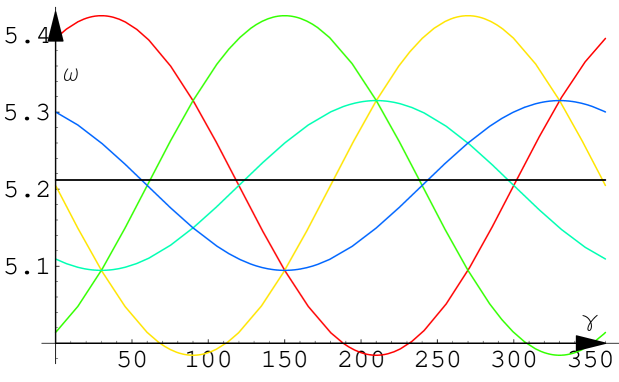
Very effective demonstration of orientation dependence is splitting of reflexes frequencies. For example, all reflexes of crystal [1 1 1] with same sum k+l+m𝑘𝑙𝑚k+l+m are degenerated at zero angle of crystal inclination. This degeneration is disappeared if we incline crystal on angle β𝛽\beta. Dependence of frequency on angle γ𝛾\gamma is shown on Figure 3. It is seen, that for the case when crystal is not inclined, frequencies for all reflexes with k+l+m=7𝑘𝑙𝑚7k+l+m=7 are the same and not change. But when crystal is inclined on β=3𝛽3\beta=3 degrees, reflexes split and their frequencies depend on γ𝛾\gamma. Let’s note, that at different values of angle γ𝛾\gamma we shall see different number of reflexes frequencies.

Refer to caption
Figure 3: Splitting of reflex k+l+m=7𝑘𝑙𝑚7k+l+m=7 (Si𝑆𝑖Si [1 1 1]) at nonzero β=3𝛽3\beta=3 E=100𝐸100E=100 KeV. Black line demonstrates dependence of peaks with k+l+m=7𝑘𝑙𝑚7k+l+m=7 on γ𝛾\gamma for zero inclination angle. Color curves show frequency dependence of reflexes (5 1 1),(1 1 5), (1 5 1), (1 3 3), (3 1 3), (3 3 1) on γ𝛾\gamma for inclination angle β=3𝛽3\beta=3 degrees.

As was shown in (8) and (9), brightness has maximal magnitude at θg0subscript𝜃𝑔0\theta_{g}\approx 0. Let’s study this geometry in more detail. It follows from (7) and requirement of 𝐤+𝐠𝐮𝐤conditional𝐠𝐮\mathbf{k+g\parallel u} for θg=0subscript𝜃𝑔0\theta_{g}=0 the condition

𝐠βu1β𝐮𝐧𝐧+𝐠βu𝐠subscript𝛽𝑢1subscript𝛽𝐮𝐧𝐧conditional𝐠subscript𝛽𝑢\frac{\mathbf{g\beta}_{u}}{1-\mathbf{\beta_{u}n}}\mathbf{n}+\mathbf{g\parallel\beta}_{u} (11)

must be fulfilled. It follows from (11), that component of vector 𝐠𝐠\mathbf{g} which is parallel to [𝐤×𝐮𝐤𝐮\mathbf{k\times u}] must be zero. Besides, component of vector in left hand side of (11) which is perpendicular to 𝐮𝐮\mathbf{u} and lies in plane of 𝐤𝐤\mathbf{k} and 𝐮𝐮\mathbf{u} must be zero also. This leads to expression for ψ=𝐠𝐯^𝜓^𝐠𝐯\psi=\mathbf{\widehat{gv}}

cosψ=1/1+(βusinθ1βucosθ)2.𝜓11superscriptsubscript𝛽𝑢𝜃1subscript𝛽𝑢𝜃2\cos\psi=1/\sqrt{1+\left(\frac{\beta_{u}\sin\theta}{1-\beta_{u}\cos\theta}\right)^{2}}. (12)

As it follows from (12), the parameters of optimal geometry depend on reflex, electron energy and observation angle. Specific observation angle corresponds to specific crystal rotation which gives maximal brightness for given reflex.

Dependence of tanθgsubscript𝜃𝑔\tan\theta_{g} on Euler angle γ𝛾\gamma is demonstrated on Figure 4. This graphic is built at fixed angles α=0,β=1.1π/4,θ=π/20.1formulae-sequence𝛼0formulae-sequence𝛽1.1𝜋4𝜃𝜋20.1\alpha=0,\beta=1.1\pi/4,\theta=\pi/2-0.1. Angle between vector 𝐤+𝐠𝐤𝐠\mathbf{k+g} and electron velocity vector 𝐯𝐯\mathbf{v} θgsubscript𝜃𝑔\theta_{g} is in vicinity to zero when γ1.46𝛾1.46\gamma\approx 1.46 for these parameters. It is evident that change of one angle parameter changes other angular parameters of target angular position and observation angle corresponding to θg=0subscript𝜃𝑔0\theta_{g}=0.

Refer to caption
Figure 4: Dependence of tanθgsubscript𝜃𝑔\tan\theta_{g} on Euler angle γ𝛾\gamma, Si [0 0 1], reflex (1 1 1). Electron energy E=75𝐸75E=75 KeV.
Refer to caption
Figure 5: Optimal geometry. Frequency dependence of emitted photon spectral angular density at θg0subscript𝜃𝑔0\theta_{g}\approx 0. γ=1.38𝛾1.38\gamma=1.38, θ=π/20.1,α=0,β=1.1π/4formulae-sequence𝜃𝜋20.1formulae-sequence𝛼0𝛽1.1𝜋4\theta=\pi/2-0.1,~{}\alpha=0,~{}\beta=1.1\pi/4. Si [0 0 1], reflex (1 1 1), electron energy E=75𝐸75E=75 KeV.
Refer to caption
Figure 6: Non-optimal geometry. Frequency dependence of emitted photon spectral angular density . γ=0𝛾0\gamma=0, θ=π/20.1,α=0,β=0formulae-sequence𝜃𝜋20.1formulae-sequence𝛼0𝛽0\theta=\pi/2-0.1,~{}\alpha=0,~{}\beta=0. Si [0 0 1], reflex (1 1 1), electron energy E=75𝐸75E=75 KeV.Point shows central frequency of diffraction peak without accounting of multiple scattering. Dynamical frequency shift corresponds to difference of this point frequency and real peak central frequency.

Figure 5 corresponds to electron current 1μA1𝜇A1~{}\mu\mathrm{A} and crystal thickness L0.1μ𝐦𝐿0.1𝜇𝐦L\approx 0.1~{}\mu\mathbf{m}. Other parameters is on the Figure It can be seen, that peak corresponding to optimal geometry is very bright and it width is about of 0.050.050.05 KeV. For comparison the dependence of spectral-angular brightness on frequency for non-optimal geometry is shown on Fig. 6. When the beam takes dispersion, then electrons which emit smaller frequencies will give greater contribution to emission due to increasing of polarizability at frequency reducing. So, peaks will shift in more soft region. On Fig. 6 point shows central frequency of diffraction peak without accounting of multiple scattering. Dynamical frequency shift corresponds to difference between these frequency. Such behavior of peak central frequency should be observed experimentally.

The brightness corresponding to optimal geometry (Fig. 5) exceeds in 100similar-toabsent100\sim 100 times the brightness for non-optimal one (Fig. 6).

One more method to suppress multiple scattering influence on radiation is using of inclined geometry geometry for PXR emitted photons observation. In the case when ψ1/(kχ0′′)Lmuch-less-thansubscript𝜓1𝑘subscriptsuperscript𝜒′′0𝐿\psi_{1}/(k\chi^{\prime\prime}_{0})\ll L (ψ1subscript𝜓1\psi_{1} is the angle between wave-vector 𝐤𝐤\mathbf{k} and crystal surface), the emission will be detected from the electron which path is of order of ψ1/(kχ0′′)subscript𝜓1𝑘subscriptsuperscript𝜒′′0\psi_{1}/(k\chi^{\prime\prime}_{0}), not Lsimilar-toabsent𝐿\sim L or 1/(kχ0′′)similar-toabsent1𝑘superscriptsubscript𝜒0′′\sim 1/(k\chi_{0}^{\prime\prime}). If ψ1/(kχ0′′)subscript𝜓1𝑘subscriptsuperscript𝜒′′0\psi_{1}/(k\chi^{\prime\prime}_{0}) is sufficiently small, emission from such path is not disturbed by multiple scattering. Combining kinematical suppression with inclined observation geometry it is possible to produce very bright and narrow peak of PXR radiation.

IV CONCLUSION

Regulation of multiple scattering action on PXR (CBS) emission by geometry choice gives possibility using relatively thick crystals for observation of diffraction peaks. Specific reflex and specific crystal orientation corresponds to specific observation angle and frequency where kinematical suppression is appeard. Therefore, experimental setup should have possibility of crystal target and detector orientation in wide spectral range.

IV.1 Acknowledgments

The work was fulfilled due to support ISTC: grant B-626.

References

  • (1) I. D.  Feranchuk, A.  Ulyanenkov, J.  Harada and J. C. H. Spence, Phys. Rev. A  62, 4225 (2000).
  • (2) Y.S.  Korobochko, V.F.  Kosmach and V.I.  Mineev, Sov.  Phys.  JETP,  21, 834 (1965).
  • (3) J.C.H.  Spence and G.  Reese, Acta  Crystallogr.  A, 42, 577 (1986).
  • (4) G.M.  Reese, J.C.H.  Spence and N.  Yamamoto, Philos. Mag. A”, 49, 697 (1984).
  • (5) V.S.  Remizovich, D. B.  Rogozkin and M. I.  Ryazanov, “Fluctuations of Free Path of Charged Particles”, EnergoAtomIzdat, Moscow, (1988).