LAL/RT 06-06
EUROTeV-Report-2006-038
June 2006
BENCHMARKING OF TRACKING CODES (BDSIM/DIMAD)
USING THE ILC EXTRACTION LINES
††thanks: Work supported by the Commission of the European Communities
under the 6th Framework Programme ”Structuring the European
Research Area”, contract number RIDS-011899.
Abstract
The study of beam transport is of central importance to the design and performance assessment of modern particle accelerators. In this work, we benchmark two contemporary codes - DIMAD and BDSIM, the latter being a relatively new tracking code built within the framework of GEANT4. We consider both the 20 mrad and 2 mrad extraction lines of the International Linear Collider (ILC) and we perform tracking studies of heavily disrupted post-collision electron beams. We find that the two codes mostly give an equivalent description of the beam transport.
1 INTRODUCTION
In a high-energy linear collider such as ILC [1], the
beams must be focused to extremely small spot sizes in order to achieve
high charge densities and, in turn, to reach the desired luminosity. This
leads to large angular divergence and energy spread for the disrupted beams,
as well as to the emission of beamstrahlung photons. A careful design
of the extraction lines must therefore be performed to transport these
outgoing beams from the interaction point to their dumps with small
losses. At ILC, two configurations are being studied for the crossing
angle at the interaction point and, as a result, for the design of the
post-collision lines. With a 2 mrad crossing angle, the main challenge
is the extraction of the disrupted beam, which has to be achieved by
sending the outgoing beam off-center in the first large super-conducting
defocusing quadrupole of the final focus beam line, as well as in the two
nearby sextupoles [2]. On the other hand, with a 20 mrad crossing
angle [3], one must deal with technical difficulties such as large
crab-crossing corrections or the construction of compact super-conducting
quadrupoles for the incoming beam lines, as well as with the passage of
the beams through the solenoid field with an angle. For the design of the
ILC extraction lines, it is essential to have a reliable simulation program
for particle tracking. In this study, we present a comparison between two
codes, DIMAD [4] and BDSIM [5], using the present versions
of the ILC post-collision lines for benchmarking purposes, in both large
and small crossing angle cases.
The DIMAD program specifically aims at studying the behaviour of particles in beam lines, by computing their trajectories using the second order matrix formalism [6]. The present version of the code ensures that the matrix treatment is correct to all orders for energy deviations [4]. This is important, as the ILC disrupted beams downstream of the interaction point can have very large energy spreads. As for the BDSIM program [5], it uses the closed solutions in linear elements, whilst for higher-order elements, a GEANT4-like stepper integration method is used. The program is written in GEANT4 [7] and provides a toolkit to simulate interactions of particles with the surrounding matter once they have left the vacuum pipe. However, for the purpose of this study, we only aim at comparing the tracking procedures in DIMAD and BDSIM.
2 DIMAD AND BDSIM TRACKING IN THE 20 MRAD EXTRACTION LINE
For this benchmarking study, we use the nominal beam parameters
for ILC at 500 GeV, for which the beam transport from
the interaction point to the dump is almost loss-free (at least with
the low-statistics input files that we use). The particle distributions
for the disrupted beams at the interaction point were obtained
with GUINEA-PIG [8] and then transported, with DIMAD or BDSIM,
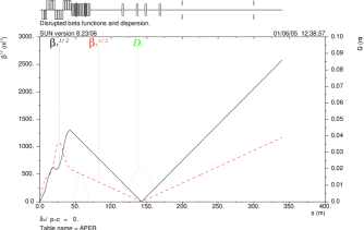
along the ILC 20 mrad extraction line. The optics used for this study
consists of a DFDF quadruplet, followed by two vertical chicanes for
energy and polarization measurements and a long field-free region that
allows the beam to grow naturally, with two round collimators to reduce
the maximum beam size at the dump, see Figure 1.
At several locations of interest, we project the transverse beam distributions obtained with each program into binned histograms and we compare them quantitatively. An illustration of this procedure is shown in Figures 2 and 3 for the transverse beam distributions obtained respectively at the secondary focus point Mexfoc, located at (where and are very small, with a vertical dispersion of 2 cm) and at the dump. The open circles show the ratio between the number of events found by DIMAD or BDSIM in a given histogram bin and the error bars account for the limited number of events per bin (very few events are found in the tails, which explains the large error bars there). The transverse distributions of the disrupted beams were also computed with DIMAD and BDSIM at several other locations in the 20 mrad extraction line. Their comparison also showed excellent agreement.
3 DIMAD AND BDSIM TRACKING IN THE 2 MRAD EXTRACTION LINE
When the colliding beams cross with a small horizontal angle of 2 mrad, the outgoing disrupted beam passes off-axis through the bore of the final quadrupole QD0, both final sextupoles, but not the second-to-final quadrupole QF1. However, the outgoing beam sees the pocket field of this latter magnet. Following this doublet, the beam is focused with a series of large bore quadrupoles. These are followed by a vertical energy clean-up chicane, diagnostic chicanes for the purpose of energy spectrometry and polarimetry, and finally a long field-free region to allow the beam to grow to the dump, in the same way as in the 20 mrad scheme. Note that, in the 2 mrad scheme, separate dumps are used for the charged beam and for the beamstrahlung photons.


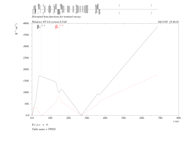
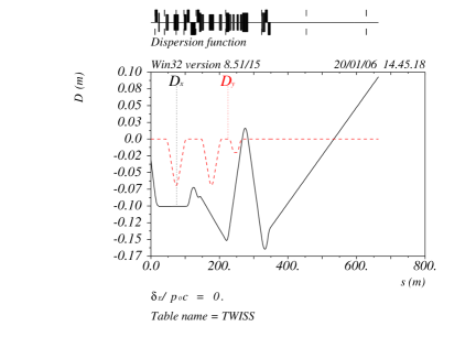
The version of the linear optics used for this study is shown in Figure 4.
Following the BDSIM/DIMAD comparison in 20 mrad scheme, we now simply describe the results obtained for the 2 mrad case, using exactly the same beam. Figures 5 to 7 show the results of the comparison at three locations along the 2 mrad extraction line. Figures 5 and 6 show the comparison at Mexfoc1 (located just after the energy clean-up chicane) and at Mexfoc2 (the secondary focus of the polarimetry chicane), respectively. As for Figure 7, it shows the comparison at the beam dump.
In these plots, we have projected the transverse beam distributions obtained from the particle tracking into bins, and we have then formed the ratio of the DIMAD prediction to the BDSIM prediction. As in the previous section, the open circles show the ratio, with the error bars accounting for the limited number of events in a given bin. All diagrams show a good agreement between DIMAD and BDSIM for the ILC 2 mrad extraction line, except at the secondary focus of the polarimetry chicane (Mexfoc2), where slight discrepancies are visible. These may be due to different treatments of the high-order effects in the optical transport through non-linear elements.


4 CONCLUSION
In this paper, we performed a detailed benchmarking study of two particle tracking codes, DIMAD and BDSIM. For this purpose, we have considered the ILC extraction lines with a crossing angle of 2 mrad or 20 mrad and, in each of these two configurations, we have performed tracking studies of disrupted post-collision electron beams. Here, only the nominal luminosity case of the 500 GeV machine was studied. We find that both programs give an equivalent description of the beam transport in all parts of the post-collision lines, except at the secondary focus for the 2 mrad design, where a small difference is visible.
References
- [1] http://www.interactions.org/linearcollider/
- [2] Y. Nosochkov et al., ”Optics of the extraction line for the 2 mrad crossing angle”, EuroTeV-Report-2006-001 and SLAC-PUB 11613.
- [3] R. Arnold, K. Moffeit, Y. Nosochkov, W. Oliver, A. Seryi, E. Torrence and M. Woods, “Design of ILC extraction line for 20 mrad crossing angle”, Proceedings of PAC 2005, Knoxville, USA.
- [4] http://www.slac.stanford.edu/accel/ilc/codes/dimad
- [5] http://flc.pp.rhul.ac.uk/bdsim.html
- [6] K.L. Brown, D.C. Carey, Ch. Iselin and F. Rothacker, “TRANSPORT, a computer program for designing charged particle beam transport systems”, SLAC 91 (1973 Rev.), NAL 91 and CERN 80-04.
- [7] GEANT4 Collaboration (S. Agostinelli et al), ”GEANT4: a simulation toolkit”, Nucl. Instr. and Meth. NIM A 506 (2003), 250-303.
- [8] D. Schulte, TESLA-97-08 (1996).