LAL/RT 06-05
EUROTeV-Report-2005-026
June 2006
Particle tracking in the ILC extraction
lines
with DIMAD and BDSIM
Abstract
The study of beam transport is of central importance to the design and performance assessment of modern particle accelerators. In this paper, we benchmark two contemporary codes, DIMAD and BDSIM, the latter being a relatively new tracking code built within the framework of GEANT4. We consider both the 20 mrad and 2 mrad extraction lines of the 500 GeV International Linear Collider (ILC) and we perform particle tracking studies of heavily disrupted post-collision electron beams. We find that the two codes give an almost equivalent description of the beam transport.
1 Introduction
In a linear collider such as ILC [1], the beams must be
focused to extremely small spot sizes in order to achieve high charge
densities and, in turn, to reach the desired luminosity. Because of the
extremely small transverse dimensions of the colliding beams, electrons
and positrons experience very strong transverse electromagnetic fields
at the interaction point, which leads to the emission of beamstrahlung
photons, as well as large angular divergence and energy spread for the
disrupted beams. A careful design of the extraction lines must therefore
be performed to transport the outgoing beams and the beamstrahlung
photons from the interaction point to their dumps with small losses.
At ILC, two configurations are being studied for the crossing angle
at the interaction point and, as a result, for the design of the
post-collision lines. With a 2 mrad crossing angle, the main challenge
is the extraction of the disrupted beam, which has to be achieved by
sending the outgoing beam off-center in the first large super-conducting
defocusing quadrupole of the final focus beam line, as well as in the two
nearby sextupoles [2, 3]. On the other hand,
with a 20 mrad crossing angle [4], one must deal with technical
difficulties such as large crab-crossing corrections or the construction
of compact super-conducting quadrupoles for the incoming beam lines, as
well as with the passage of the beams through the solenoid field with
an angle. For the design of the ILC extraction lines, it is
essential to have a reliable simulation program for particle tracking.
In this study, we present a comparison between two codes, DIMAD [5]
and BDSIM [6], using the present versions of the ILC post-collision
lines for benchmarking purposes, in both large and small crossing angle
cases.
The DIMAD program specifically aims at studying the behaviour of particles in circular machines or beam lines, by computing their trajectories using the second order matrix formalism [7]. The present version of the code makes sure that the matrix treatment remains correct to all orders for energy deviations [5]. This is important here, as the ILC disrupted beams downstream of the interaction point can have very large energy spreads. The BDSIM program [6] uses the closed solutions in linear elements, whilst for higher-order elements, a GEANT4-like stepper integration method is used. The program is written in GEANT4 [8] and provides a toolkit to fully simulate interactions of particles with the surrounding matter once they have left the vacuum pipe. However, for the purpose of this study, we only aim at comparing the tracking procedures in DIMAD and BDSIM: a more detailed evaluation of the losses, with all particle-matter interactions and with the subsequent background generation, is underway and will be the subject of a future report. In order to compare the tracking procedures in DIMAD and BDSIM, we will proceed as follows. In Section 2, we consider the ILC extraction line with a 20 mrad crossing angle, where the disrupted beam remains centered in all magnetic elements. We compare single particle trajectories as well as beam transverse spectra, as they are obtained with DIMAD and BDSIM at various positions along the extraction line. Then, in Section 3, we perform a similar analysis with the ILC 2 mrad post-collision line, where the geometry is slightly more complicated, since the disrupted beam goes off-center in the first magnetic elements. Finally, a summary is given in Section 4.
2 DIMAD and BDSIM tracking in the 20 mrad extraction line
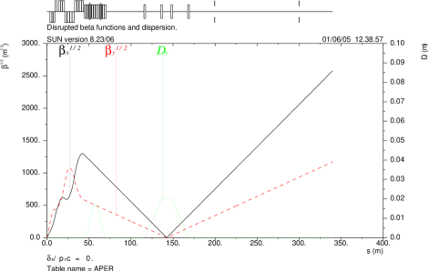
In order to compare the tracking procedures in DIMAD and BDSIM, we first consider the ILC 20 mrad extraction line. Thanks to the large crossing angle, one can use a dedicated line to transport each outgoing beam from the interaction point to its dump. In the present design of the ILC 20 mrad extraction line [4], the disrupted beam and the beamstrahlung photons go through the same magnets to a common dump. The optics consists of a DFDF quadruplet, followed by two vertical chicanes for energy and polarization measurements and a long field-free region that allows the beam to grow naturally, with two round collimators to reduce the maximum beam size at the dump. Figure 1 shows the betatron functions and the vertical dispersion in this design.
2.1 Single off-momentum particles
For the sake of simplicity, we switch off any type of particle-matter interaction, including for the moment synchrotron radiation, in BDSIM, since we want to benchmark the tracking procedures only. Let us first compare single particle trajectories. For this purpose, we track four particles with ideal transverse coordinates (, , , ) at the interaction point and increasing fractional energy deviation . The first one has the nominal energy (=0) and it thus follows a centered reference path in all elements of the extraction line. The three other particles have lower energies (): as a result, they follow different paths inside the magnetic chicanes, as shown in Figure 2. Note however that, since the total vertical dispersion of both chicanes is equal to zero, all particles remain on the same trajectory downstream of the chicanes. For all energies, there is a perfect agreement between the single particle trajectories obtained with DIMAD (with no synchrotron radiation) and with the tracking procedure of BDSIM.
Note that the paths are slightly different when the synchrotron radiation is
taken into account. To illustrate this, let us track one 500 GeV electron
along the ILC 20 mrad post-collision line with DIMAD, with and without
synchrotron radiation, for (see Figure 3) or
(see Figure 4).


The energy loss due to synchrotron radiation along the ILC post-collision line is larger for an electron with than for an electron with , as expected. When the electron radiates a fraction of its energy, it leaves the reference path inside the bending magnets. Figures 3 and 4 show that this effect is relatively more important for particles having the nominal energy (which should be centered in all magnetic elements) than for particles with a non-zero energy deviation (which are already passing off-center in all magnetic elements). Note that the losses occuring during the transport of the disrupted beams from the interaction point to the dumps concern almost exclusively particles with a large energy deviation and almost never particles close to the nominal energy. Therefore, we expect the synchrotron radiation to have a limited influence on the power lost along the ILC extraction line and, for the rest of this study, we will switch off this effect in both DIMAD and BDSIM.
2.2 Complete phase-space
Having shown that DIMAD and BDSIM agree perfectly when following single particles with various energy deviations, let us now compare transverse distributions of particles at several locations along the ILC extraction line. For this purpose, since we are not interested in a detailed estimation of the losses along the post-collision line but only in the behaviour of the tracking in both simulations, we use the suggested nominal beam parameters for ILC at a centre-of-mass energy of 500 GeV [10], for which the beam transport from the interaction point to the dump is almost loss-free (at least with the low-statistics input files that we use for this study). The corresponding particle distributions for the disrupted beams at the interaction point, just after the bunch crossing, obtained with the GUINEA-PIG program [9] are shown in Figure 5.

Such particle distributions are transported along the ILC 20 mrad extraction line with either DIMAD or BDSIM. At several locations of interest (typically before, in and after each vertical magnetic chicane), we project the transverse beam distributions obtained with each program into binned histograms and we compare them quantitatively. An illustration of this procedure is shown in Figures 7 and 7 for the transverse beam distributions ( and ) that are obtained respectively at the secondary focus point MEXFOC, located at (where and are very small, with a vertical dispersion of 2 cm) and at the dump. The open circles show the ratio between the number of events found by DIMAD or BDSIM in a given histogram bin and the error bars account for the limited number of events per bin (very few events are found in the tails, which explains the large error bars there).


The transverse distributions of the disrupted beams were also computed with DIMAD and BDSIM at several other locations in the 20 mrad extraction line. Their comparison also showed excellent agreement.
3 DIMAD and BDSIM tracking in the 2 mrad extraction line
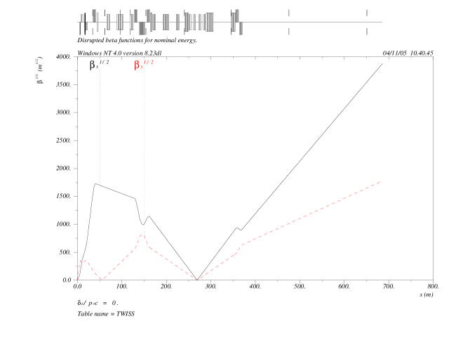
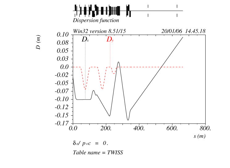
In this section, we shall compare the DIMAD and BDSIM tracking procedures for the ILC 2 mrad extraction line [2, 3]. This layout was developed in an attempt to preserve the physics advantages of the head-on scheme suggested in the TESLA TDR [11], whilst mitigating the associated technological challenges. In this scheme, the colliding beams cross with a small horizontal angle of around 2 mrad. The outgoing disrupted beam then passes off-axis through the first magnets of the incoming final focus beam line, so these magnets require a large magnetic bore. In the design used for this work, the outgoing beam passes through the bore of the final quadrupole QD0, both final sextupoles but not the second-to-final quadrupole QF1. The outgoing beam sees however the pocket field of this latter magnet. The strongest design challenge lies in this shared doublet region, with current work focusing on the choice of final doublet magnet technology [3]. The extraction line of the 2 mrad scheme follows the 20 mrad design, with the inclusion of downstream diagnostic structures. The current version of the optics was presented at Snowmass 2005 [12, 13]. The corresponding linear optics is shown in Figures 8 and 9.
Following the doublet, the beam is focused with a series of large bore quadrupoles. This is followed by an energy clean-up vertical chicane, diagnostic chicanes for the purpose of energy spectrometry and polarimetry and, in the same way as in the 20 mrad scheme, a long field-free region to allow the beam to grow to the dump. Note that, in the 2 mrad scheme, separate dumps are used for the charged beam and for the beamstrahlung photons.
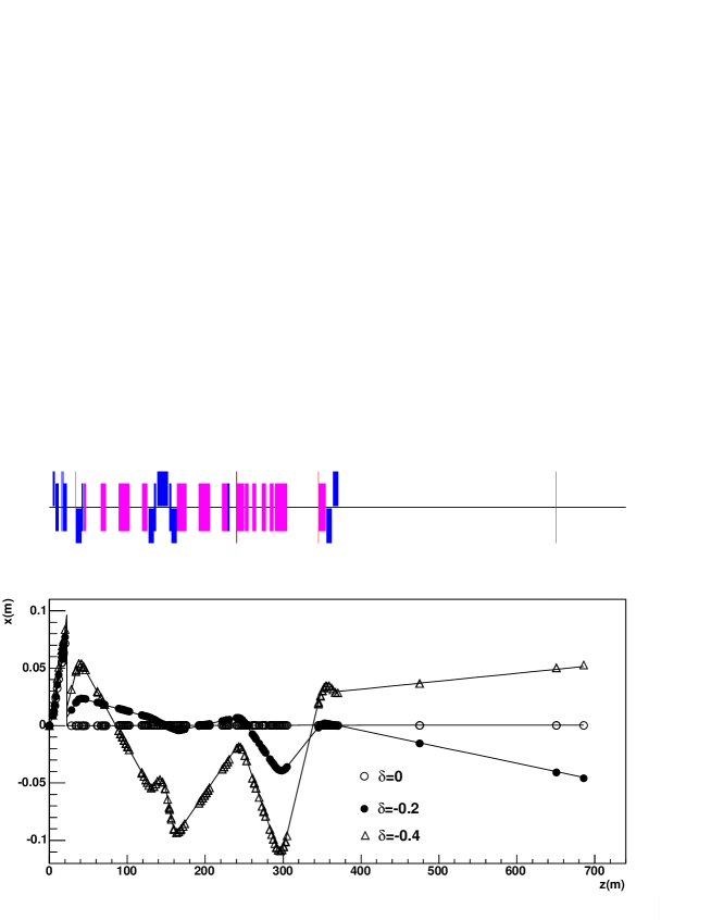
3.1 Single off-momentum particles
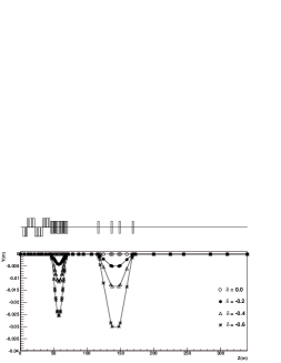
We shall now, in exactly the same way as for the 20 mrad case, track
single particles. We consider three particles at the interaction point,
with ideal transverse coordinates and energy deviations =0,
-0.2 and -0.4. The first particle traces out the nominal trajectory.
The off-momemtum particles trace out different trajectories, just as
in the 20 mrad case, and the same comments with regard to the downstream
chicanes apply. For all momentum deviations, we see a perfect agreement
between DIMAD and BDSIM.
The 2 mrad case has an extra degree of complexity compared to the 20 mrad case. This is because the beam is off-axis in the final doublet, including in one case the pocket field, which requires the introduction of a multipole expansion in BDSIM. The extraction line after the final doublet is then aligned to ensure that the outgoing beam is on-axis in this part of the beamline. For the single particle tracking, we align the extraction line to the nominal particle. When we consider beam distributions (for example in the next section), we align the extraction line after the final doublet to the outgoing beam centroid. This transformation is implemented as an active transformation of the beam in DIMAD and as a 3D transformation of the reference coordinate system in BDSIM. Note that the shift of the particle trajectories can be seen in Figure 10.
3.2 Complete phase-space
Following the discussion of the 20 mrad BDSIM/DIMAD comparison in the
previous section, we now simply describe the results of the comparison
for the 2 mrad case. The studies in this section were performed for a
250 GeV disrupted beam with the same nominal parameters as in the previous
section (see Figure 5).
Figures 11 to 13 show the results of the comparison at
three extraction line locations. Figures 11 and 13
show the comparison at MEXFOC1, which is located after the energy
clean-up chicane, and at MEXFOC2, which is the secondary focus of the
polarimetry chicane, respectively. As for Figure 13, it shows
the comparison at the beam dump.
In these plots, chosen to be at various places of interest, we have projected the transverse beam distibutions obtained from the tracking into bins, and we have formed the ratio of the DIMAD prediction to the BDSIM prediction. As in the previous section, the open circles show the ratio, with the error bars accounting for the limited number of events in a given bin (again, the larger error bars are from the beam tail where there are less events). All diagrams show a good agreement between DIMAD and BDSIM for the ILC 2 mrad extraction line, except at the secondary focus of the polarimetry chicane (MEXFOC2), where some slight discrepancies are visible. These may be due to the different treatments of high-order effects in the optical transport for non-linear elements (see Section 1).


4 Conclusion
In this paper, we performed a detailed benchmarking study of two particle
tracking codes, DIMAD and BDSIM. For this purpose, we have considered
the ILC extraction lines with a crossing angle of 2 mrad or 20 mrad
and, in each of these two configurations, we have performed tracking
studies of heavily disrupted post-collision electron beams. Here, only
the nominal luminosity case of the 500 GeV machine was studied. We find
that both programs give an equivalent description of the beam transport
in all parts of the post-collision lines, except at the secondary focus
for the 2 mrad design.
A similar benchmarking study is presently being performed in order to compare the power losses obtained with DIMAD and BDSIM along the ILC 2 mrad and 20 mrad post-collision lines. A more comprehensive simulation study of the backgrounds from secondary particles will then follow.
Acknowledgement
This work is supported by the Commission of the European Communities under the 6th Framework Programme ”Structuring the European Research Area”, contract number RIDS-011899. We would also like to thank Ilya Agapov, Grahame Blair and John Carter for the useful discussions and their assistance regarding the development of BDSIM.
References
- [1] http://www.interactions.org/linearcollider/
- [2] R. Appleby, D. Angal-Kalinin, P. Bambade, B. Mouton, O. Napoly and J. Payet [TESLA Collaboration], CARE/ELAN Document-2004-020, hep-ex/0412026.
- [3] R. Appleby et al., The proceedings of LCWS05, Stanford, CA, 18-22 March 2005. physics/0507063.
- [4] R. Arnold, K. Moffeit, Y. Nosochkov, W. Oliver, A. Seryi, E. Torrence and M. Woods, “Design of ILC extraction line for 20 mrad crossing angle”, Proceedings of PAC 2005, Knoxville, USA.
- [5] http://www.slac.stanford.edu/accel/ilc/codes/dimad
- [6] http://flc.pp.rhul.ac.uk/bdsim.html
- [7] K.L. Brown, D.C. Carey, Ch. Iselin and F. Rothacker, “TRANSPORT, a computer program for designing charged particle beam transport systems”, SLAC 91 (1973 Rev.), NAL 91 and CERN 80-04.
- [8] GEANT4 Collaboration (S. Agostinelli et al), ”GEANT4: a simulation toolkit”, Nucl. Instr. and Meth. NIM A 506 (2003), 250-303.
- [9] D. Schulte, TESLA-97-08 (1996).
- [10] T. Raubenheimer, “Suggested ILC Beam Parameter Range”, February 28, 2005 (see http://www-project.slac.stanford.edu/ilc/acceldev/beamparameters.html).
- [11] TESLA Technical Design Report, DESY 2001-011, ECFA 2001-209, TESLA Report 2001-23, TESLA-FEL 2001.05
- [12] Y. Nosochkov et al., ”Optics of the extraction line for the 2 mrad crossing angle”, EuroTeV-Report-2006-001 and SLAC-PUB 11613.
- [13] Y. Nosochkov, “Extraction Line Optics with 2 mrad Crossing Angle”, presentation at Snowmass 2005, Colorado, USA.