Turbulence characteristics of the Bödewadt layer in a large shrouded rotor-stator system
Abstract
A three-dimensional direct numerical simulation (3D DNS) is performed to describe the turbulent flow in an enclosed rotor-stator cavity characterized by a large aspect ratio and a small radius ratio ( and the inner and outer radii of the rotating disk and the interdisk spacing). Recent comparisons with velocity measurements [1] have shown that, for the rotational Reynolds number ( the rate of rotation of the rotating disk and the kinematic viscosity of water) under consideration, the stator boundary layer is 3D turbulent and the rotor one is still laminar. Budgets for the turbulence kinetic energy are here presented and highlight some characteristic features of the effect of rotation on turbulence. A quadrant analysis of conditionally averaged velocities is also performed to identify the contributions of different events (ejections and sweeps) on the Reynolds shear stress.
Conference on Turbulence and Interactions TI2006, May 29 - June 2, 2006, Porquerolles, France
Introduction
Besides its primary concern to many industrial applications, the rotor-stator problem has proved a fruitful means of studying turbulence in confined rotating flows. This specific configuration is indeed among the simplest ones where rotation brings significant modifications to the turbulent field. The present paper is devoted to the study of the turbulent flow in an enclosed high-speed rotor-stator system of large aspect ratio. The flow is of Batchelor type and belongs to the regime denoted IV by Daily and Nece [2]. These authors provided an estimated value for the local Reynolds number at which turbulence originates with separated boundary layers, ( the radial location) for . However, experiments have revealed that transition to turbulence can appear at a lower value of the Reynolds number within the stator boundary layer (the Bödewadt layer), even though the flow remains laminar in the rotor boundary layer (the Ekman layer). Recently, the 3D computed solution presented here has been compared to velocity measurements performed at IRPHE [1]. It has been shown that, for the rotational Reynolds number , the Bödewadt layer is turbulent and the rotor one is still laminar. The purpose of this work is to provide detailed data of the turbulent boundary layer along the stator side in a large enclosed system ().
Numerical approach
The numerical approach is based on a pseudo-spectral technique using Chebyshev polynomials in the radial and axial directions with Fourier series in the azimuthal direction associated with a semi-implicit second order time scheme. An efficient projection method is introduced to solve the pressure-velocity coupling. A grid resolution composed of respectively in radial, axial and azimuthal directions has been used, with a dimensionless time step . Numerical computations have been carried out on NEC SX-5 (IDRIS, Orsay, France).
Results and discussion
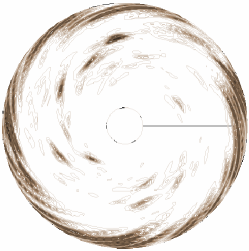
The detailed description of the mean field and of the axial variations of the Reynolds stress tensor is given in [1]. Nevertheless, we recall the main results. A good agreement has been obtained between the 3D solution and the experimental data, whereas the axisymetric solution leads to a steady laminar flow. The flow is of Batchelor type: the two boundary layers developed on each disk are separated by a central rotating core characterized by a quasi zero radial velocity and a constant tangential velocity. The Bödewadt layer along the stator is centripetal, three-dimensional as the Townsend structural parameter is lower than the limit value , and turbulent with turbulence intensities increasing from the axis to the periphery of the cavity. On the contrary, the Ekman layer on the rotor is centrifugal and laminar. The turbulence is observed by the formation of turbulent spots developing along spiral arms towards the periphery of the cavity, as seen in figure 1 from the instantaneous iso-values of the turbulence kinetic energy within the stator boundary layer.
Turbulence kinetic energy budgets
The balance equation for the turbulence kinetic energy can be written:
| (1) |
with the advection term , the production term , the turbulent diffusion , the viscous diffusion , the velocity-pressure-gradient correlation and the dissipation term .
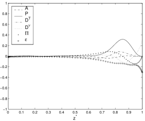
(a)
(b)
Figures 2a and 2b show the axial variations along of the different terms involved in the transport equation (1) at two radial locations. It is clearly seen that all these terms vanish towards the rotor side (), confirming the laminar nature of this zone up to the stator boundary layer (). At the stator wall, the viscous diffusion balances the dissipation as well known in 3D turbulent boundary layer. Within the Bödewadt layer, even though some interaction between the different terms involved is observed, the major contributions come from the production, the dissipation and the viscous diffusion terms. The production is balanced by the dissipation and the viscous diffusion, the level of which increases in association with the thickening of the boundary layer towards the periphery. The production increases with increasing radius as already observed with the levels of the normal Reynolds stresses [1]. The maximum of the production term is obtained at the wall coordinate ( the total friction velocity and the axial coordinate) for and at for , which confirms the approximately self-similar behavior of the Bödewadt layer. The levels of the viscous diffusion increase when moving towards the outer casing, where the highest turbulence intensities prevail. It indicates that viscous effects still play an important role in the turbulence towards these regions, which does not allow for a distinct delineation of the viscous sublayer. This indicates also the weak nature of the turbulence obtained at this Reynolds number.
Conditional-averaged quadrant analysis

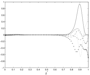
(a)

(b)
To gain a better insight on the near-wall structure of the turbulent boundary layer along the stator side, a conditional-averaged quadrant analysis is performed to identify the contributions of intense intermittent bursting events (ejections and sweeps) on the Reynolds shear stress producing vortical structures. It corresponds to four subdivisions of the fluctuation field according to the combination of the tangential and axial velocity fluctuations [3, 4]. Following the definitions given in [5] in a fixed frame, a strong sweep is associated with and (quadrant Q4) and a strong ejection with and (quadrant Q2). In the first quadrant Q1, and , while in the third quadrant Q3, and . The quadrant analysis is applied at corresponding to the location of the maximum value of the turbulent shear stress. We have also considered the value to determine strong events, as used in [3, 4]. We display in figures 3a and 3b the variations with ( the wall coordinate in the radial direction) of the conditionally averaged Reynolds shear stress normalized by the unconditionally ensemble averaged Reynolds shear stress near a strong ejection (fig.3a) and a strong sweep (fig.3b). The contributions of each quadrant are also presented. The figures 3a and 3b clearly show that the ejection (Q2) and sweep (Q4) quadrants contribute much more to the Reynolds shear stress production than the two other quadrants. On the other hand, it seems that the weakness of the turbulence in the present simulation accentuates the features observed in previous works. The results obtained support the conclusions of Littell and Eaton [3] and Lygren and Andersson [5], in contrast with the findings of Kang et [4]: the asymmetries observed are dominated by Reynolds stress-producing coherent structures (sweep and ejection). Lygren and Andersson [5] concluded that clockwise vortices contribute much more to the Reynolds shear stress than counter-clockwise vortices. The same behavior applies in the presence of a sweep event. In this case, the levels of the surrounding ejections approach the strong sweep level and are even slightly beyond the fixed criterion condition , as seen in figure 3b, while the levels of sweeps around a strong ejection are less important (fig.3a), in agreement with the results of [5]. Case 1 vortices, having induced near-wall velocity in the direction of the crossflow, are found to be the major source of generation of special strong events.
Conclusion
DNS calculations have been used to describe the turbulent boundary layer along the stator side in a large enclosed rotor-stator cavity. For the rotational Reynolds number under consideration , the Bödewadt layer is 3D turbulent, whereas the Ekman layer on the rotor is still laminar. The transition to turbulence is associated with the onset of localized turbulent spots spiraling up along the stator side. The turbulence kinetic energy budgets have revealed that production is the major contribution with a maximum obtained at independently of the radial location, confirming the self-similar behavior of the Bödewadt layer. The results of the quadrant analysis support the conclusions proposed by [3, 5]. The asymmetries observed by these authors have been clearly detected and the analysis of conditionally averaged streamwise and wall-normal velocity components confirms that these asymmetries mainly arise from the contributions of quadrants Q2 and Q4, responsible for the generation of ejection and sweep events. Therefore, Case 1 vortices are found to be the major source of generation of special strong events.
References
- [1] S. Poncet & A. Randriamampianina ”Écoulement turbulent dans une cavité rotor-stator fermée de grand rapport d’aspect,” C.R. Mécanique, vol. 333, pp. 783-788, 2005.
- [2] J.W. Daily & R.E. Nece ”Chamber dimension effects on induced flow and frictional resistance of enclosed rotating disks,” ASME J. Basic Eng., vol. 82, pp. 217-232, 1960.
- [3] H.S. Littell & J.K. Eaton ”Turbulence characteristics of the boundary layer on a rotating disk,” J. Fluid. Mech., vol. 266, pp. 175-207, 1994.
- [4] H.S. Kang, H. Choi & J.Y. Yoo ”On the modification of the near-wall coherent structure in a three-dimensional turbulent boundary layer on a free rotating disk,” Phys. Fluids, vol. 10 (9), pp. 2315-2322, 1998.
- [5] M. Lygren & H.I. Andersson ”Turbulent flow between a rotating and a stationary disk,” J. Fluid Mech., vol. 426, pp. 297-326, 2001.