Resonant transparency of materials with negative permittivity
Abstract
It is shown that the transparency of opaque material with negative permittivity exhibits resonant behavior. The resonance occurs as a result of the excitation of the surface waves at slab boundaries. Dramatic field amplification of the incident evanescent fields at the resonance improves the resolution of the the sub-wavelength imaging system (superlens). A finite thickness slab can be totally transparent to a p-polarized obliquely incident electromagnetic wave for certain values of the incidence angle and wave frequency corresponding to the excitation of the surface modes. At the resonance, two evanescent waves have a finite phase shift providing non-zero energy flux through the non-transparent region.
pacs:
52.25.Os, 42.30.Lr, 52.35.Lv, 42.25.HzI Introduction
Propagation of the electromagnetic radiation in materials with negative dielectric permittivity (permeability) or the so called left-handed materials (LHM) has attracted great deal of attention in recent years kindel75 ; dragila85 ; bliokh05 ; fang05 . The increased interest in properties of such media has been driven by their potential applications in various branches of science and technology. One possible application is related to the possibility of creating the so called superlens: a subwavelength optical imaging system without the diffraction limit fang05 ; shvets04 ; pendry00 ; podolskiy05 . The superlens phenomenon is essentially based on amplification of evanescent waves, facilitated by the excitation of the surface plasmons pendry00 . Plasma with overcritical density is a simplest example of the negative material; for . Phenomena that take place in such plasmas are important in a number of areas, in particular for the inertial confinement fusion (ICF) experiments kindel75 ; aliev77 ; bychenkov01 .
In this work we show that the amplification of the evanescent waves originating from the interaction of two evanescent fields (decaying and growing in space) has a resonant character related to the excitation of surface modes. Such amplification of the evanescent field allows the penetration of the electromagnetic radiation to depths much greater compared to the incident light wave lengthdragila85 . The evanescent wave incident on the negative slab is strongly amplified when the resonant conditions for the surface modes are met. For materials with the resonance occurs for finite values of the wave vector (for , the resonance occurs for , where is the in-plane wave vector component (p-polarization is considered). The presence of resonances with finite values of the in-plane wave vector may significantly improve the overall resolution of the subwavelength imaging system.
Resonant excitation of a surface mode is also the underlying mechanism behind the absolute transparency of a finite thickness slab of material with to the incident propagating electromagnetic waves ()dragila85 ; fourkal06 . In this case, the resonant excitation of surface modes by the incident light can be achieved via the presence of a single transition layer with on one side of the slab with fourkal06 . The superposition of two evanescent waves provides a finite energy flux through the region with , which is equal to that in the incident electromagnetic wave. The radiation is then re-emitted at the other side of the opaque slab.
II Interference of the evanescent waves and effect of superlensing
Non-propagating (evanescent) modes are basic solutions to the Maxwell’s equations for the electromagnetic fields in materials with negative dielectric permittivity. Often such modes have been neglected assuming that the boundary conditions in an infinite medium preclude the exponentially growing modes while the decaying modes do not contribute to the transmission. It has recently been noted however pendry00 that in a slab of material with negative permittivity both (growing and decaying) components are present, resulting in amplification of the evanescent modes. As shown by Pendry pendry00 , the effect of amplification of the evanescent spectrum of the incident light (originating from the object) by ”negative” materials can be advantageously used for subwavelength imaging applications, potentially leading to optical system without the diffraction limit or superlens.
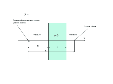
The imaging problem can be described in terms of the optical transfer function ( designates the in-plane wave vector directed along the surface of the material), defined as the ratio of Fourier components of image field to object field, (for ) at a given imaging plane . The transfer function can be found by considering a -polarized wave (electric vector in the plane of incidence) incident from vacuum on a thin overcritical density slab of thickness , dielectric permittivity and magnetic permeability as shown in Figure 1. The optical properties of this slab are obtained by taking the ratio of the field in the region to that at the object plane (in current calculations the object plane is assumed to be at ). The electromagnetic fields in each region of interest are found from solving the well known wave equation,
| (1) |
with a general solution having the following form,
| (2) |
where . The electromagnetic fields in vacuum regions ( and ) represent a sum of incident and reflected waves (), and a transmitted wave (). Matching solutions at different boundaries by requiring the continuity of and across interfaces, one arrives at the expression for the transfer function,
| (3) | |||
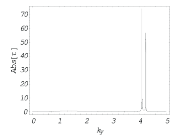
where is a distance between the source and the image planes and . Figure 2 shows the absolute value of the optical transfer function at a distance from the source. As one can see, there are in general two sharp peaks in the transfer function occurring for certain resonant values of the in-plane wave vector where the spectrum is completely evanescent. The peaks correspond to the resonant excitation of surface plasmons that are supported by the interface between the thin overcritical density medium and vacuum. This means that only those fields for which may resonantly couple to this particular surface mode and get dramatically amplified through constructive interference (these are the spectral components that carry sub-diffraction-limited resolution of the object). In fact, the zeros of the denominator in Eq. 3
define the dispersion relation for the plasma surface eigenmode that is supported by the thin overdense medium. The above equation can be reduced to the following form:
| (4) |
In the general case, for a finite value of there exist two solutions to Eq. 4, as seen from Figure (2) corresponding to a coupled surface wave running on opposite sides of the slab. As becomes large so that , the two solutions degenerate and we obtain,
| (5) |
which is the well known dispersion relation for surface plasmons on an overdense medium-vacuum interface. It is worth noting here that the transfer function given by expression 3 is exact and no approximations were used in its derivation. It includes the resonant contribution of surface modes with a finite in-plane wave vector and in the limit , it is reduced to that obtained in Ref. podolskiy05 where the authors investigated the resolution limit of the slab of ”negative” material with dielectric permittivity and magnetic permeability . It should also be noted that the location (in wave vector space) of the two resonances not only depends on the absolute value of the dielectric constant but also the thickness of the slab . For a very thin slab, the two resonances are separated (smaller slab thicknesses result in greater peak separation in space). As the slab thickness increases, the two resonant points move toward each other, eventually merging together forming a single peak. All of these features in the transfer function have not been noticed in the previous investigations since the authors limited their calculations to the asymptotic case and . As we will see below, the presence of such resonances may advantageously be used in the design of superlens for improved image resolution and intensity.
The transfer function can be used to find the reconstructed field in the image plane in the form
| (6) |
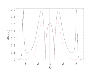
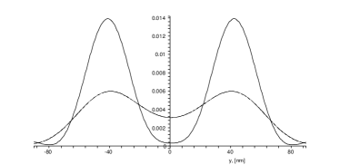
where is the wave vector spectrum of the source (imaged object). Thus, the ability of the system to image the object is completely determined by the optical transfer function (3), which in itself depends on many system’s physical parameters. In an ideal case, the transfer function should transfer all spatial harmonics equally or for . In reality however, the transfer function is a non-monotonous function of the wave vector , medium material type defined by , its thickness , and the position of the imaging plane relative to the position of the object plane. The superlensing can only be realized for certain set of the above parameters. Figure 3 shows the optical transfer function for two layers of materials with dielectric permittivities and at the imaging plane . As one can see the transmission band (in the wave vector space) is significantly broadened in the second material () due to the resonant excitation of a surface plasmon with a finite value of the wave vector . Such surface plasma wave is not excited in material with (assuming the slab thickness such that the condition is satisfied), as can be seen from the dispersion relation (5).
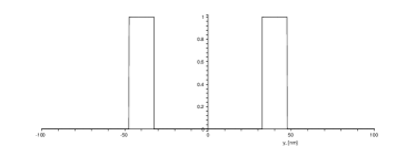
Let us estimate how well we can image an object using these two materials. For a sake of simplicity we assume that our object is represented by two slits of a certain width located at a given distance away from each other as shown in Figure 4. Substituting the Fourier transform of the object together with the transfer function (3) into Eq. 6 we arrive at the reconstructed image shown in Figure 5 for the case when the incident light wavelength is nm. As one can see, both materials provided considerable focusing, yielding the sub-wavelength resolution of the object. However, as we expected the image resolution and its intensity for the second layer () is superior to that using material with . This suggests that there is a range of system parameters for which a significant focusing can be achievedfang05 necessitating a further parametric study in order to understand the relation between different physical parameters of the system.
III Surface wave induced total transparency of material with negative permittivity
Surface wave induced amplification of incident electromagnetic waves with spectral components of in-plane wave vectors satisfying the condition has been considered in the previous section. It was shown that the resonant amplification occurs as a result of the excitation of a surface wave. A slab of negative material surrounded by vacuum supports such a surface mode for which its phase velocity is always sub-luminal or . As a result, only those modes of the incident light for which have been amplified. It is possible however to amplify the propagating modes with too, thus creating the conditions for the absolute transparency to the incident propagating wave. This can be done by creating conditions for the excitation of a surface mode with phase velocity greater than that of the speed of light.
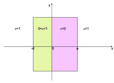
Consider -polarized light obliquely incident from vacuum on a two-layer structure having dielectric permittivity distribution shown in Fig. 6. Such a system can be formed by placing an undercritical density plasma layer (with thickness and electron density corresponding to the plasma frequency ) to an overcritical density plasma layer (with thickness and electron density corresponding to the plasma frequency ). The plasma-plasma interface supports a surface wave with dispersion relation found from the solution to the Maxwell’s equationskindel75 ,
| (7) |
where , , ; ; is normalized to the plasma frequency in the region where and is normalized to the classical skin depth . It can be easily seen that the phase velocity of the surface wave on a plasma-plasma interface can be greater than that of light, so that they can couple to radiating electromagnetic fields. This means that the incident -polarized electromagnetic wave may excite a surface mode on a plasma-plasma interface if the resonant condition (external field frequency and its wave vector’s tangential component have to match those that are determined from the dispersion relation for the plasma surface wave) is satisfied. The optical properties of this dual-layer system can be found from matching the fields of the incident/reflected electromagnetic waves with those of the surface wave at the three interfaces. The electromagnetic field in each region is a solution to the wave equation 1 with general solution given by expression 2. The electromagnetic fields in vacuum regions ( and ) represent a sum of incident and reflected wave (), and a transmitted wave (). Matching solutions at different boundaries by requiring continuity of and across interfaces, we obtain the unknown expansion coefficients with the transmission coefficient having the following form,
| (8) | |||
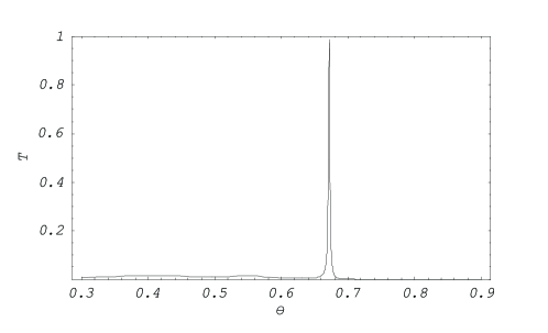
where . Figure 7 shows the transmission coefficient as a function of the incidence angle. As one can see there is a sharp increase in the transmission properties of the system when the angle of incidence matches certain resonant value of at which point the transmission coefficient reaches unity. The resonant value exactly corresponds to that given by an expression (7) for the dispersion relation of the surface plasma wave. Thus, the anomalous transmission occurs even for a system consisting of an undercritical density plasma layer adjacent to an overcritical density plasma slab, so that there is no need to form a sandwich-like structure as argued in Refs. dragila85 ; dragila87 in which a second surface plasma wave has to be excited on the opposite side of the overcritical density layer to achieve the same effect. In other words, the anomalous light transmission can be achieved through excitation of a single surface plasma wave. The transmission coefficient is also a non-monotonous function of both plasma layer thickness with a single maximum reached at certain correlated values determined from the interference condition between evanescent fields in both plasma slabs.
IV Evanescent wave interference and the energy transport
It is often assumed that the evanescent waves do not carry the energy. Therefore, in the problem of total transparency of a layered structure there occurs a question of how the energy is carried through the non-transparent media where the only solutions are the evanescent modes. One must remember however that the general solution inside the negative medium is a sum of two exponential functions, one that decays with the distance ( points in the propagation direction) and the other grows . For the superposition of decaying and growing modes, ( is purely imaginary decay constant), the component of the time averaged Poynting vector
may become finite when the combination has a finite imaginary part, which requires a finite phase shift between and . Therefore, a finite energy flux occurs as a result of the superposition of two evanescent modes with a finite phase shift . We shall call this the interference of the evanescent modes.
It is easy to show that the required phase shift can be obtained when two evanescent modes inside the negative region are matched to the outgoing (transmitted) wave in vacuum. Matching of the evanescent solutions with the incident vacuum wave (at the other side of the negative region) shows that the total transmission may be obtained only when the transition layer with is includedfourkal06 . The condition of the absolute transparency is equivalent to the resonant condition for the excitation of the surface plasma mode. At the resonance the Poynting flux inside the slab becomes equal to that of the incident radiation and the opaque plasma slab becomes absolutely transparent. This can be a possible mechanism of the anomalously high transparency of overdense plasma recently observed in the experimentbychenkov05 .
V Summary
In conclusion, we have shown that the excitation of surface modes leads to the resonant transparency of optically opaque materials. Presence of such resonances may improve the resolution and the signal intensity of the sub wavelength imaging system. It has been also shown that the resonant excitation of surface modes is an underlying mechanism behind the total transparency of an overdence plasma slab to the incident electromagnetic wave. The energy flux through the negative region occurs as a result of the interference of the evanescent modes.
This work is in part supported by Strawbridge Family Foundation, and NSERC Canada.
References
- (1) J. M. Kindel, K. Lee, and E. L. Lindman, Phys. Rev. Lett. 34, 134 (1975).
- (2) R. Dragila, B. Luther-Davies, and S. Vukovic, Phys. Rev. Lett. 55, 1117 (1985).
- (3) Y. Bliokh, J. Felsteiner, and Y. Slutsker, Phys. Rev. Lett. 95, 165003 (2005).
- (4) N. Fang, H. Lee, C. Sun, and X. Zhang, Science 308, 534 (2005).
- (5) G. Shvets, Y. Urzhumov, Phys. Rev. Lett. 93, 243902 (2004).
- (6) J. B. Pendry, Phys. Rev. Lett. 85, 3966 (2000).
- (7) V. A. Podolskiy, N. A. Kuhta, and G. W. Milton, Appl. Phys. Lett. 87, 231113 (2005).
- (8) Y. M. Aliev, O. M. Gradov, and A. Y. Kyrie, Phys. Review A 15, 2120 (1977).
- (9) V. Yu. Bychenkov, W. Rozmus, and A. Maksimchuk, Plasma Phys. Rep. 27, 1017 (2001).
- (10) T. Matsuoka, A. Maksimchuk, T. Lin, O. V. Batishchev, A. A. Batishcheva, and V. Yu Bychenkov, 47th Annual Meeting of the Division of Plasma Physics (2005).
- (11) E. Fourkal, I. Velchev, C.-M. Ma, and A. Smolyakov, Submitted to Physics of Plasmas
- (12) S. Vukovic and R. Dragila, J. Opt. Soc. Am. B 3, 1585 (1986).
- (13) R. Dragila and S. Vukovic, Optics Letters 12, 573 (1987).
.