Low-Light-Level Optical Interactions with Rubidium Vapor in a Photonic Bandgap Fiber
Abstract
We show that a Rubidium vapor can be produced within the core of a photonic band-gap fiber yielding an optical depth in excess of 2000. Our technique for producing the vapor is based on coating the inner walls of the fiber core with an organosilane and using light-induced atomic desorption to release Rb atoms into the core. We develop a model to describe the dynamics of the atomic density, and as an initial demonstration of the potential of this system for supporting ultra-low-level nonlinear optical interactions, we perform electromagnetically-induced transparency with control-field powers in the nanowatt regime, which represents more than a 1000-fold reduction from the power required for bulk, focused geometries.
pacs:
42.50.Gy,32.80.Qk,42.70.QsRemarkable advances have been made in the past decade in generating and controlling quantum states of light using atomic vapors, including the realization of on-demand single-photon sources 1 , manipulation of photonic states 2 , and storage and retrieval of the states with high fidelity 3 ; 4 . Much of the motivation for these efforts has been to realize a practical quantum network 5 . In most cases, the underlying optical process for realizing these schemes has been the phenomenon of electromagnetically-induced transparency (EIT) 6 in which a coherent superposition of atomic states is created by a strong control field such that an optically thick atomic ensemble is rendered transparent to a weak, resonant probe field. The concept of EIT has been applied and expanded to schemes that allow two extremely weak fields, which in principle can consist of single photon pulses, to strongly interact 7 ; 8 ; 9 ; 10 . Practical implementation of these proposals in which a single photon can switch another photon will lead to the realization of critical components (e.g., a quantum phase gate) for quantum information applications 11 .
The two generic requirements to achieve EIT-based, ultralow-level optical interactions are: 1) a large optical depth , where is the density of the atomic sample of length , and is the atomic absorption cross-section, and 2) confinement of the light beams to an area comparable to the atomic scattering cross-section of 8 ; 9 ; 10 ; 12 . For example, the phase shift due to nonlinear interactions between few photon-pulses in the proposed scheme of André et al. 10 and the inverse of the critical power required to switch a signal field in the four-level scheme of Harris and Yamamoto 8 are each proportional to . In order to maximize the optical depth, a natural choice for the atomic ensemble is an alkali atom due to its relatively simple energy-level structure and its large as compared to, for example, molecules with ro-vibrational transitions 13 . There is a limit on how much can be increased by increasing the density since this will result in undesirable dephasing effects due to atomic collisions. Alternatively, increasing the length of the atomic sample can further enhance the optical depth. However, in a bulk focused geometry, this length is limited to the Rayleigh length, which can only be increased by a corresponding increase in beam area 5 ; 10 , and thus no change in the quantity .
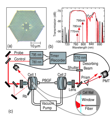
In this Letter, we realize a new experimental geometry for alkali vapors that overcomes the limitations of bulk focused geometries by using light-induced atomic desorption (LIAD) to produce controllable densities of Rb atoms within a suitably coated core of a photonic band-gap fiber (PBGF). The photonic crystal structure 14 surrounding the core of a PBGF [see Fig. 1(a)] provides an unmatched ability to tightly confine light with a gas in a region a few microns in diameter over meter-long distances, and thus provides an ideal system to perform nonlinear optics at extremely low light levels 10 ; 12 . Recent demonstrations of nonlinear optical processes in PBGFs using gases with relatively weak nonlinearities has led to the observation of low-threshold stimulated Raman scattering 15 , high-power soliton generation 16 , and coherent resonant interactions with molecules 13 ; 16a . By using a gas such as an alkali vapor with a strong nonlinear optical response, such a fiber system can form a the basis for creation, manipulation, storage and transmission of photonic states in a fiber geometry. However up until now, the ability to inject alkali atoms into PBGFs has eluded researchers due to the strong interaction of the vapor with silica walls of the fiber.
The primary challenge to creating a useful vapor of Rb atoms within a PBGF is that Rb vapor attacks and adheres to silica glass fiber walls through both physisorption, in which the atoms stick to the surface for a finite time, and through chemisorption, in which the atoms are lost to the wall 17 . These issues are particularly severe for a fiber with a core 6-m in diameter 18 , which is a factor of smaller than the atomic mean free path at room temperature. Furthermore, for the fraction of atoms undergoing physisorption, the spin-decoherence is large 19 , which makes this system unsuitable as a practical quantum device. However, treating a glass surface with paraffin or siloxane coatings 20 significantly alters the Rb-surface interaction properties such that the wall-induced dephasing rate decreases by four orders of magnitude with a significant reduction in chemisorption when compared with that for uncoated silica glass walls 21 . In addition, atoms attached to such coated walls can be released by sudden exposure to optical radiation through the non-thermal process termed LIAD 22 ; 23 ; 24 .
We applied these techniques to the fiber geometry by surface-modifying the core walls of a PBGF {AIR-6-800, Crystal Fibre, with a core diameter of 6 m [Fig.1(a)] and a bandgap extending from 750 to 810 nm, chosen to accommodate the D1 and D2 lines of Rb at 795 nm and 780 nm, respectively [Fig.1(b)]} with a monolayer of moieties by self-assembly of octadecyldimethylmethoxysilane (ODMS) 25 via hydrolysis and condensation from solution. This monolayer deposition technique avoids the clogging of the fiber core that would occur for vacuum deposition of paraffin. The coating solution was introduced from polyolefin syringes to the PBGF via swaged PEEK fixtures, , incubated in the core to facilitate the monolayer deposition, and then flushed out. As seen in Fig.1(b), the bandgap of the fiber is preserved following the coating process. Following the monolayer deposition, the ends of the PBGF of length cm are placed in separate vacuum cells which are each connected to an ultra-high vacuum system [Fig. 1(c)]. One of the cells [left cell, in Fig. 1(c)] is subsequently exposed to natural Rb vapor, at a pressure of Torr, and a beam from an external-cavity diode laser reflected from a mirror inside the cell allows for monitoring the Rb density in the cell, which is kept at cm-3. Bulk condensation of Rb vapor inside the fiber core is prevented by maintaining a constant temperature along the entire length of the fiber. In the absence of LIAD, a finite fraction of atoms diffuse a length down the fiber core of radius , and this atomic flux, which is proportional to the thermal velocity, can be estimated in the Knudsen limit 26 . A steady-state condition, known as ”ripening”, is reached when this flux equals the rate of adsorption to the wall surface at 24 . For the PBGF in which , this ripening time can be extremely large. For simplicity, we rely on the Knudsen flow for the atoms to diffuse down the core. However, the atomic flux can be significantly enhanced with techniques such as light-induced drift 27 or dipole-force guidance 18 into the core. The total number of atoms in the core is determined by monitoring the transmission of a weak laser beam coupled to the core and by scanning over the transition. We take into account the density contribution due to the beam path in the cell before the fiber [Fig. 1(c)] and fit the resulting absorption trace to the transmission coefficient,
| (1) |
where is the atomic density at position in the core, and the atomic cross-section of the transition is a function of the atomic velocity , the homogeneous linewidth , and the laser frequency . The cross-section is averaged over the Doppler profile . From the fit of the experimental trace to Eq. 1, we estimate that in the absence of LIAD the total number of atoms in the core to be , where is the cross-sectional area of the fiber core.
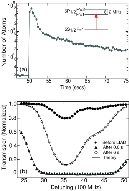
In our experiments, the intensity of the probe beam is maintained at 100 pW, which is an order of magnitude lower than the measured saturation power of 3 nW in the core. By coupling a desorbing beam counterpropagating to the probe beam into the core and tuned far off resonance at 770 nm, we observe a dramatic increase in the total number of atoms. Figure 2(a) shows that the atomic population undergoes a nearly instantaneous increase by three orders of magnitude after the turn-on of the 1-mW desorbing beam, with a maximum optical depth in excess of 2000. While a recent experiment 28 has reported Rb desorption from porous silica, we have not observed measurable desorption in uncoated fibers. From the fitted absorption profile, we estimate a homogeneous linewidth of = 96 MHz for the transitions. The broadening associated with the dipole dephasing of the atoms colliding with core wall can be estimated from the wall-collisional frequency 85 MHz, where is the thermal velocity, which suggests that the dominant contribution to the homogeneous linewidth is due to the wall-collisional dephasing as opposed to atomic collisional broadening. This is consistent with our data that shows the linewidth to be nearly constant as a function of time as the density varies over two orders of magnitude.
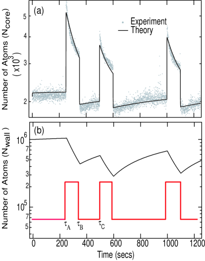
As a result of the transient nature of the density of atoms within the core, application of this fiber system to low-light-level nonlinear optics requires a basic understanding of the dynamics of the desorbed atoms in order to determine the time window in which useful interactions can be performed. We apply the following simple model 23 ; 24 to explain most of the features of the observed density dynamics. The temporal evolution of the total number of atoms in the core is modeled by the equation,
| (2) | |||
The first term on the right-hand-side is the rate of loss of atoms from the core due to collisions with the walls, with the probability that an atom sticks to the wall. The second term is the contribution from the atoms stuck to the core walls. This increase consists of two contributions: a light-independent thermal desorption rate and a light-induced desorption rate, which is proportional to the intensity of the desorbing beam at the core wall with a proportionality constant . It is via this second process that the atomic density and the optical depth of the system can be varied. The last factor in Eq. 2 represents the relaxation of the atomic number to the steady-state value at a rate . An equation similar to Eq. 2 is assumed for , where the first two factors contribute with opposite signs, leading to an increase and decrease of atoms stuck to the walls, respectively. Fig. 3(a) shows a plot of variation in the atomic population for various exposures of the desorbing beam of , together with a fit of the adopted model. The model was fitted to the experiment up to time [Fig. 3(b)], and the subsequent comparison of the theory to the experiment shows excellent agreement.
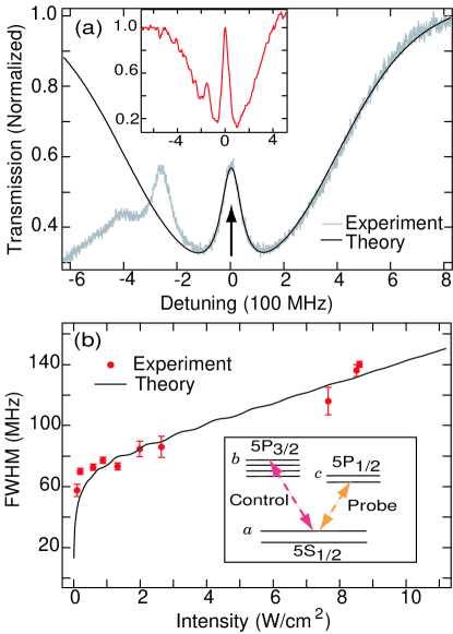
To demonstrate the potential of this system to facilitate nonlinear optics at low-light levels, we investigate EIT in a -type system with a probe at 100 pW and with control powers as low as 10 nW; these control powers are smaller by more than a factor of 1000X than what is typically used to achieve EIT in bulk geometries 29 . The probe is tuned to the transition of the line of at 795 nm, and a control field, copropagating with the probe, is tuned to the transition of the line at 780 nm. For this particular level scheme [inset of Fig. 4(b)], optical pumping between the hyperfine levels is avoided, since the transition is dipole forbidden. Furthermore, the probe-field saturation and the optical pumping between the magnetic sublevels tend to cancel each other, and as a result the observed transparency is primarily due to pure EIT 29 . To analyze this system, we solve the density-matrix equations for a 3-level system in steady state, with level as the ground state and with and as the two excited states [Fig. 4(b)]. The coherence to first order in the probe field is given by 13 ,
| (3) | ||||
where () and () are the Rabi frequency and detuning, respectively, for the control (probe) field, are the steady-state population distributions, are the dephasing rates, and is the decay rate of level . The imaginary part of the Doppler-averaged susceptibility, calculated from this coherence, is integrated over the length of the fiber to fit to the transmission trace of the probe field.
Figure 4 shows results in which a 1-mW desorbing beam releases Rb atoms into the core, and a series of probe transmission spectra are taken at ensuing time intervals. The time (250 ms) to obtain a trace is chosen to be long compared to the atomic time scales (100’s ns) but short compared to the time scales (secs) associated with the desorption dynamics of the atomic density in the core. The input power of the probe field is set to 100 pW, and that of the control field is varied from 10 nW to 3 W. Figure 4(a) shows a typical trace of the probe field transmission in presence of a 361-nW control field, together with the corresponding theoretical fit as calculated from Eq. (3). Using the fitting procedure described in 13 , we estimate a decay rate for the coherence between the two upper states to be = 24 MHz and the two-level decoherence rates to be between 90-100 MHz. Figure 4(b) shows the measured transparency full-width at half maximum (FWHM) together with the corresponding FWHM calculated from Eq. 3. The error bar denotes the variation in measurements which were taken at different time intervals of atomic desorption [ Fig 2(a)]. At higher powers or for transitions in which optical pumping and saturation effects contribute, larger than 90% transparencies are observed [see inset of Fig. 4(a)].
In conclusion, we have demonstrated a new technique to create a significant density of Rubidium vapor in the core of a PBGF and as a proof of concept, we have demonstrated EIT in this system with a control power as low as 10 nW which represents more than a factor of reduction, as compared to acetylene-based EIT in PBGF [13, 17]. Such a system represents a new experimental geometry for performing nonlinear optics at extremely low light levels due to its unmatched combination of strong light confinement and long interaction lengths with atoms of large optical cross-section.
We thank D. Gauthier, J. E. Sharping, K. D. Moll, K. Koch for stimulating discussions and D. Gauthier for the loan of the photomultiplier tube. We gratefully acknowledge support by the Center for Nanoscale Systems, supported by the NSF under Grant No. EEC-0117770, the Air Force Office of Scientific Research under Contract No. F49620-03-0223, and DARPA under the Slow-Light program.
References
- (1) A. Kuzmich et al., Nature 423, 731 (2003).
- (2) M. D. Lukin, Rev. Mod. Phys. 75, 457 (2003).
- (3) C. Liu et al., Nature 409, 490 (2001).
- (4) D. F. Phillips et al., Phys. Rev. Lett. 86, 783 (2001).
- (5) L.-M. Duan et al., Nature 414, 413 (2001).
- (6) S. E. Harris, Phys. Rev. Lett. 62, 1033 (1989).
- (7) H. Schmidt and A. Imamoglu, Opt. Lett. 21, 1936 (1996).
- (8) S. E. Harris, Y. Yamamoto, Phys. Rev. Lett. 81, 3611 (1998).
- (9) S. E. Harris, L. V. Hau, Phys. Rev. Lett. 82, 4611 (1999).
- (10) A. André et al., Phys. Rev. Lett. 94, 063902 (2005).
- (11) The Physics of Quantum Information: Quantum Cyrptograpy, Teleportation, and Quantum Computation, edited by D. Bouwmeester et al. (Springer, New York, 2000).
- (12) H. Schmidt and A. R. Hawkins, Appl.Phys. Lett. 86, 032106 (2005).
- (13) S. Ghosh et al., Phys. Rev. Lett. 94, 093902 (2005).
- (14) R. F. Cregan et al., Science 285, 1537 (1999).
- (15) F. Benabid et al., Science 298, 399 (2002).
- (16) D. G. Ouzounov et al., Science 301, 1702 (2003).
- (17) F. Benabid, P. Light, F. Couny, and P. Russell, Opt. Express 13, 5694-5703 (2005)
- (18) J. H. de Boer, Dynamical Character of Adsorption, (Oxford University Press, London, 1968).
- (19) M. J. Renn et al., Phys. Rev. Lett. 75, 3253 (1995).
- (20) W. Happer, Rev. Mod. Phys. 44, 169 (1972).
- (21) J. C. Camparo, J. Chem Phys 86, 1533 (1987).
- (22) M. A. Bouchiat and J. Brossel, Phys. Rev. 147, 41 (1966).
- (23) A. Gozzini et al., Nuovo Cimento D 15, 709 (1993).
- (24) S. N. Atutov et al., Phys. Rev. A 60, 4693 (1999).
- (25) E. B. Alexandrov et al., Phys. Rev. A 66, 042903 (2002).
- (26) C. R. Kessel and S. Garnick, Langmuir 7, 532 (1991).
- (27) M. N. Kogan, Rarefied Gas Dynamics, (Plenum Press, New York, 1969).
- (28) H. G. C. Werij et al., Phys. Rev. Lett. 52, 2237 (1984).
- (29) A. Burchinati et al., Europhys. Lett 67, 983 (2004).
- (30) D. J. Fulton et al., Phys. Rev. A 52, 2302 (1995).
- (31) A. Javan et al., Phys. Rev. A 66, 013805 (2002).