Development of Multi-Pixel Photon Counters
Abstract
The multi-pixel photon counter (MPPC) is a newly developed photodetector with an excellent photon counting capability. It also has many attractive features such as small size, high gain, low operation voltage and power consumption, and capability of operating in magnetic fields and in room temperature. The basic performance of samples has been measured. A gain of 106 is achieved with a noise rate less than 1 MHz with 1 p.e. threshold, and cross-talk probability of less than 30% at room temperature. The photon detection efficiency for green light is twice or more that of the photomultiplier tubes. It is found that the basic performance of the MPPC is satisfactory for use in real experiments.
I MULTI-PIXEL PHOTON COUNTERS
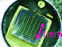
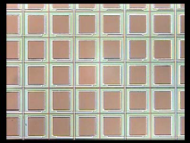
The multi-pixel photon counter (MPPC) is a new photodetector developed by Hamamatsu Photonics, Japan HPK . An MPPC consists of many (100 to 1000) small avalanche photodiodes (APDs) in an area of typically 1 mm2. Figure 1 shows a picture of an MPPC with 100 pixels.
Each APD micropixel independently works in limited Geiger mode with an applied voltage a few volts above the breakdown voltage (). When a photoelectron is produced, it induces a Geiger avalanche. The avalanche is passively quenched by a resistor integral to each pixel. The output charge from a single pixel is independent of the number of produced photoelectrons within the pixel, and can be written as
where is the applied voltage and is the capacitance of the pixel. Combining the output from all the pixels, the total charge from an MPPC is quantized to multiples of and proportional to the number of pixels that underwent Geiger discharge (“fired”). The number of fired pixels is proportional to the number of injected photons if the number of photons is small compared to the total number of pixels. Thus, the MPPC has an excellent photon counting capability.
For the MPPC, the operation voltage is a few volts above the breakdown voltage and well below 100 V. The pixel capacitance is on the order of 10–100 fF, giving a gain of 105–106. These features enable us to read out the signal from the MPPC with simple electronics. In addition, because the thickness of the amplification region is a few m, it is insensitive to an applied magnetic field and the response is fast.
Because of these great advantages, several particle physics experiments are going to use the MPPC. The T2K (Tokai-to-Kamioka) long baseline neutrino oscillation experiment T2K , which is now under construction and will start in 2009, has chosen the MPPC as one of the baseline photosensors for the near neutrino detector complex. Calorimeters for the International Linear Collider are another project that is considering use of the MPPC ILC-CAL . In these experiments, MPPCs will be used to detect photons from plastic scintillators guided by wavelength-shifting fibers. With larger area devices or a light collection system, the MPPC may be used for the aerogel-RICH particle identification system in a B-factory upgrade Super-Belle . The features of MPPCs are suitable not only for particle physics experiments but for much wider applications such as astrophysics, space science, material science, or medical instruments.
The MPPC is a newly developed device and its performance is rapidly improving. In this report, the latest status of the development and future prospects are presented.
II TEST SAMPLE
We have tested two types of the latest samples of MPPCs produced by Hamamatsu Photonics. The difference between them is the number of pixels—one has 100 pixels with a 100 m pitch and the other has 400 pixels with a 50 m pitch. A device with a 25 m pitch and 1600 pixels is also being tested, although not reported here. The main characteristics of the tested samples are summarized in Table 1. The time response of the MPPC depends on the quenching resistor and capacitance of each pixel. The numbers shown in Table 1 are the typical values.
| Number of pixels | 100 | 400 |
|---|---|---|
| Pixel pitch (m) | 100 | 50 |
| Area | 1.01.0 mm2 | |
| Operation voltage | 69–70 V | |
| Signal temporal width (ns, typ.) | 40 | 10 |
III BASIC PERFORMANCE
The basic performance of the MPPC is measured with light from an LED. All results shown in this section are for a sample 400 pixel device.
III.1 Raw signal
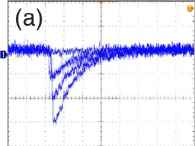
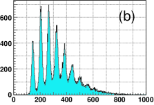
Figure 2(a) shows the raw signal from an MPPC taken with an oscilloscope. The MPPC is illuminated by pulsed light from an LED at low intensity and the oscilloscope is triggered in synch with the LED pulse. The responses for multiple triggers are overlaid in the figure. One can see excellently separated signals corresponding to one, two, and three fired pixels. Figure 2(b) shows the output charge read out by an analog-to-digital converter (ADC). The charge corresponding to different numbers of fired pixels is again well separated (or quantized) as peaks in the ADC distribution at equal intervals. This indicates that the gain of each micropixel is uniform in an MPPC. These observations demonstrate the excellent photon counting capability of the MPPC.
III.2 Gain and noise rate
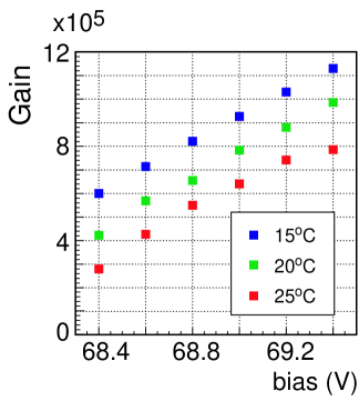
The gain is measured by illuminating an MPPC with light from an LED. From the number of ADC counts between a well-separated pedestal and the peak corresponding to a single fired pixel (Fig. 2(b)), we derive the charge corresponding to a single fired pixel, . The gain is defined as divided by the charge of an electron. Figure 3 shows the measured gain as a function of the applied voltage. The measurement is performed inside a temperature-controlled chamber and the data at 15, 20, and 25∘C are shown. The measured gain is 3105–1.2106 and linearly depends on the applied voltage as expected. The breakdown voltage decreases with lower temperature, resulting in larger gain at a fixed applied voltage. The temperature coefficient is about 3%/∘C.
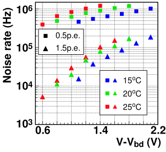
The noise rate is measured by counting the rate above a threshold without external light input. The results at 15, 20, and 25∘C are shown in Fig. 4. The horizontal axis in Fig. 4 shows the difference between the applied voltage and the breakdown voltage . The breakdown voltage is derived by linearly extrapolating the gain-voltage curve in Fig. 3 to the point where the gain becomes zero. With a threshold equivalent to 0.5 photoelectrons (p.e.)111Here, “p.e.” means the number of detected photoelectrons, and is assumed to be the same as the number of fired pixels when those numbers are small., the noise rate is 0.5–1 MHz. However, it decreases by about or more than an order of magnitude if the threshold is set to 1.5 p.e. The noise rate decreases as the temperature becomes lower. The temperature coefficient of noise rate at 0.5 p.e. threshold is %/∘C. These observations imply that the dominant component of the noise is due to the discharge of single pixels induced by thermally generated carriers.
We have tested three samples of MPPCs of the same type. Although the number of the tested devices is limited, we find that the device-by-device variation of the characteristics is small: with an applied voltage of 68.8 V, the maximum difference in the gain is less than 3%, while that of the noise rate is about 7%. We plan to test much larger numbers of devices in the near future.
III.3 Cross-talk probability
The cross-talk between neighboring micropixels has been observed. The origin of the cross-talk is presumed to be optical photons emitted during avalanche crosstalk-ref which enter neighboring micropixels and trigger another Geiger discharge.
The probability of causing cross-talk is estimated from the fraction of events with more than one p.e. to that with one p.e. in randomly triggered events without external light. We assume that the events with more than one p.e. are caused by the cross-talk from the original Geiger discharge in a single pixel. The effect from accidental coincidence of two independent discharges is estimated from the fraction of pedestal events, assuming a Poisson distribution for the original Geiger discharge, and has been subtracted.
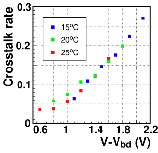
Figure 5 shows the cross-talk probability as a function of the applied voltage above . The cross-talk probability is found to be almost independent of the temperature. However, it depends on the applied voltage. The measured cross-talk probability is at an acceptable level for certain applications (e.g. for the T2K neutrino experiment). However, for applications that require good linearity with wide dynamic range (e.g. ILC calorimeters), this may limit the performance of the device, and improvement may be necessary.
III.4 Photon detection efficiency
The photon detection efficiency (PDE) is an important parameter for the performance of the MPPC. For an MPPC, the PDE is written as a product of three effects:
The geometrical efficiency represents the fraction of active area in a micropixel. It depends on the design and the size of a pixel, but is about 0.5 for current samples. The quantum efficiency of the APD, QE, depends on the wavelength of photon and is typically 0.7–0.8 in the range of current interest. The probability of inducing a Geiger discharge when a photoelectron is generated, , depends on the applied voltage.
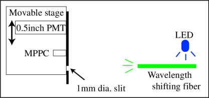
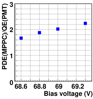
We have measured the PDE of an MPPC relative to that of a PMT using a setup shown in Fig. 6. An MPPC and a PMT are illuminated with green light from a wavelength shifting fiber, Kuraray Y11, through a slit with 1 mm diameter. We use Hamamatsu PMT H3165-10 with bialkali photo-cathode as a reference. Comparing the number of detected photo-electrons between the MPPC and the PMT, the relative PDE is measured. In order to avoid the effect of cross-talk, the number of photoelectrons for the MPPC is derived from the fraction of pedestal (= 0 p.e.) events to the total number of trigger, assuming a Poisson distribution. For the PMT, the number of photoelectrons is calculated by dividing the mean output charge by the charge corresponding to 1. p.e.
Figure 7 shows the results of the measurement at 15∘C. The PDE of the MPPC for green light is about or more than twice the QE of the PMT. A measurement of the absolute PDE with a calibrated photodiode will be done in the near future.
III.5 Response to large numbers of photons
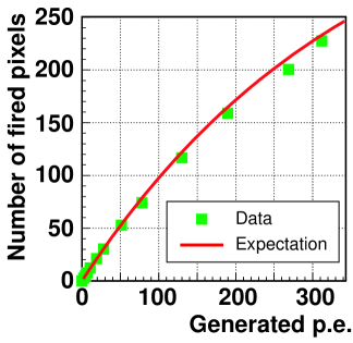
The linearity of the MPPC response to a large amount of light is intrinsically limited by the finite number of micropixels. Figure 8 shows the number of fired pixels of an MPPC as a function of light intensity. The number of generated photoelectrons inside the active area is estimated by the intensity of the light monitored by a PMT. The red curve shows the expected response of the MPPC based on the known number of pixels and the measured cross-talk probability. The deviation from the expected curve is found to be within 5%. Thus, the response of the MPPC is well described by the number of pixels and measured cross-talk rate.
IV TEST WITH A LASER INJECTION SYSTEM
In order to check the response of each micro APD pixel, we have tested the MPPC with a pulsed laser system. The laser has a spot size on the surface of an MPPC with a diameter of about 10 m so that the uniformity of the response inside a micropixel can be studied. The MPPC is placed on a X-Y movable stage that can be controlled with 1 m accuracy. The wavelength and the temporal width of the laser are 825 nm and 50 ps, respectively. For this test, a sample MPPC with 100 pixels is used.
IV.1 Uniformity inside a micro APD pixel
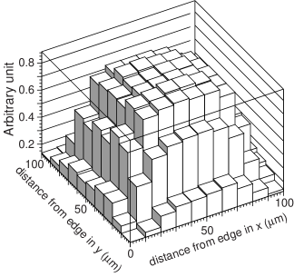
First, the dependence of the response to the position within a micropixel is studied. The light spot is injected onto a pixel and the area within a pixel is scanned with 10 m pitch. Figure 9 shows the measured response for one pixel. Because we do not know the number of injected photons in this measurement, the axis is arbitrary and show the relative response. It is found that the response is uniform within the active area of the micropixel.
IV.2 Pixel-to-pixel uniformity
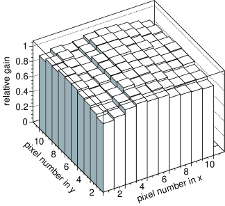
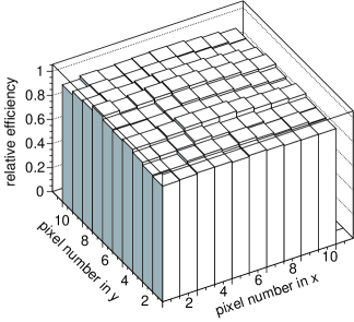
The pixel-to-pixel uniformity of the gain and the relative efficiency are tested by injecting light in the center of each pixel. The results are shown in Fig. 10. The axis is normalized so that the average over all pixels is 1.0. The gain and relative efficiency are found to be uniform within 3.6% and 2.5% in RMS, respectively.
V SUMMARY AND PROSPECTS
The multi-pixel photon counter (MPPC) is a newly developed photodetector with an excellent photon counting capability. It also has many attractive features such as small size, high gain, low operation voltage and power consumption, and capability of operation in magnetic fields.
We have shown that the basic performance of the MPPC is promising and actually already satisfactory for use in real experiments: a gain of 106 is achieved with noise rate less than 1 MHz with 1 p.e. threshold and cross-talk probability of less than 30% at room temperature. The photon detection efficiency for green light is twice or more that of a photomultiplier tube.
The development of MPPCs has advanced well in the past 2 years, and the basic functionality of the device has been established. We will continue the R&D for more practical development aiming at real use as well as wider application. The future development will include realization of devices with (but not limited to):
-
•
larger area,
-
•
reduced cross-talk,
-
•
a larger number of pixels, and
-
•
better photon detection efficiency.
Also, the following issues must be investigated for practical use.
-
•
long term stability,
-
•
quality control under mass production,
-
•
development of suitable readout electronics, and
-
•
packaging and coupling to radiator.
In addition, for wider application we need to investigate:
-
•
radiation hardness,
-
•
timing resolution, and
-
•
high rate capability.
Although there remains some work necessary before real application, we already have plans for most of this work in the near future.
The MPPC is one of the most attractive devices for photon detection in future high energy physics, astrophysics, material science and medical uses.
Acknowledgements.
The authors wish to thank the support from the KEK management for the detector technology project. We are thankful to T. Yoshida for useful suggestions as a reviewer of the project. We acknowledge the semiconductor division of Hamamatsu Photonics K. K. for providing us with test samples. We express their special thanks to National Institute of Informatics for their support of Super-SINET, and to KEK Computing Research Center for HEPnet-J, which enabled efficient information sharing. We are grateful to S. Oser for careful reading of this manuscript and useful discussions. This work was supported in part by a Grand-in-Aid for Scientific Research from Ministry of Education, Science and Technology under Contract No. 17340071.References
- (1) Hamamatsu Photonics K. K., http://www.hamamatsu.com .
- (2) Y. Itow et al., “The JHF-Kamioka neutrino project,” eprint arXiv:hep-ex/0106019 ; “Letter of Intent: Neutrino Oscillation Experiment at JHF,” available online from http://neutrino.kek.jp/jhfnu/ .
- (3) GLD Concept Study Group, “GLD Detector Outline Document,” available online from http://ilcphys.kek.jp/gld/documents/dod/glddod.pdf .
- (4) S. Hashimoto (ed.) et al., “Letter of intent for KEK Super B Factory,” KEK-REPORT-2004-4.
- (5) N. Akil et al., “A multimechanism model for photon generation by silicon junctions in avalanche breakdown,” IEEE Trans. Electron Devices, 46 1022 (1999).