Wave propagation in the anisotropic metamaterial with single-sheeted hyperboloid dispersion relation
Abstract
We investigate the wave propagation in the anisotropic metamaterial with single-sheeted hyperboloid dispersion relation. Based on boundary conditions and dispersion relations, we find that the opposite amphoteric refraction, such that E- (or H-) polarized waves are positively refracted whereas H- (or E-) polarized waves are negatively refracted, can occur at the interface associated with the anisotropic metamaterial. Under a certain condition, both E- and H-polarized waves can exhibit the same single-sheeted hyperboloid or straight dispersion relation, while the two polarized waves exhibit different propagation characteristics. We expect some potential device applications can be derived based on based on the unique amphoteric refraction properties.
pacs:
78.20.Ci, 41.20.Jb, 42.25.GyI Introduction
In classic electrodynamics, it is well known that the electrodynamic properties of anisotropic materials are significantly different from those of isotropic materials Yariv1984 ; Born1999 . In general, E- and H- polarized waves propagate in different directions in an anisotropic material. For regular anisotropic materials, all tensor elements of permittivity and permeability should be positive. The advent of a new class of metamaterials with negative permittivity and permeability has attained considerable attention Veselago1968 ; Smith2000 ; Pendry2000 ; Shelby2001 ; Parazzoli2003 ; Houck2003 . Lindell et al. Lindell2001 have shown that anomalous negative refraction can occur at an interface associated with an anisotropic metamaterials, which does not necessarily require that all tensor elements of and have negative values. Recently, The studies of such anisotropic metamaterials have received much interest and attention Hu2002 ; Smith2003 ; Zhou2003 ; Luo2005 ; Shen2005 ; Luo2006a ; Luo2006b ; Depine2006a ; Depine2006b .
The electromagnetic plane waves propagating in the conventional anisotropic crystal exhibit sphere or ellipsoid wave-vector surfaces Yariv1984 ; Born1999 . In the anisotropic metamaterial, however, the electromagnetic plane waves can exhibit two new kinds of wave-vector surfaces, that is, single-sheeted or double-sheeted hyperboloid Lindell2001 ; Hu2002 ; Smith2003 . As a result, some new wave propagation characteristics will appear. Because of the importance in achieving some potential applications, we will focus our interesting on the anisotropic metamaterial in which both E- and H-polarized waves have the single-sheeted hyperboloid dispersion relations.
In this paper, we present a detailed investigation on the wave propagation characteristics in the anisotropic metamaterial with single-sheeted hyperboloid dispersion relation. First we derive the single-sheeted hyperboloid dispersion relation from the Maxwell equations. Next we explore the propagation properties of wave vector and Poynting vector, and show that E- and H-polarized waves will exhibit opposite amphoteric (positive or negative) refraction characteristics. Then we want to explore the case that both E- and H-polarized have the same single-sheeted hyperboloid dispersion relation, and find this kind of media can not be regarded as quasiisotropic. Finally we study the waves propagation in some special plane, and find both E- and H-polarized waves can exhibit the same straight dispersion relation.
II Plane-wave propagation in anisotropic media
It is currently well accepted that a better model is to consider anisotropic constitutive parameters, which can be diagonalized in the coordinate system collinear with the principal axes of the metamaterial. If we take the principal axis as the axis, the permittivity and permeability tensors have the following forms:
| (7) |
where and () are the permittivity and permeability constants in the principal coordinate system.
Following the standard proceed, we choose the axis to be normal to the interface, the and axes locate at the plane of the interface. We consider the propagation of a planar wave with angular frequency as and from the free space into an anisotropic metamaterial. The field can be described by Maxwell’s equations
| (8) |
For the plane waves in free space, Maxwell’s equations yield the accompanying dispersion relation has the familiar form:
| (9) |
Here is the component of the incident wave vector. is the frequency, and is the speed of light in vacuum. A more careful calculation of Maxwell’s equations gives the dispersion relations in anisotropic media:
| (10) |
where represents the component of transmitted wave-vector. The above equation can be represented by a three-dimensional surface in wave-vector space. This surface is known as the normal surface and consists of two shells. It can be easily shown that there are two types of linearly polarized plane waves, namely E-polarized and H-polarized plane waves.
To simplify the proceeding analyses, in Eq. (10) we have introduced the following relation:
| (11) |
It should be mentioned that Eq. (11) is a necessary but not a sufficient condition for uniaxially anisotropic media Shen2005 ; Luo2006a . Without loss of the generality, we introduce the condition . In general, the corresponding wave-vector surfaces are a combination of ellipsoid or single-sheeted hyperboloid or double-sheeted hyperboloid. Because of the importance in some potential applications, we focused our interest on the case that both E- and H-polarized waves exhibit single-sheeted hyperboloid wave-vector surfaces.
III single-sheeted hyperboloid dispersion relation
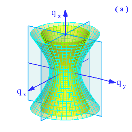
In this section, we want to explore the case that the two single-sheeted hyperboloid wave-vector surface do not intersect. We assume the revolution axes of the two single-sheeted hyperboloid coincide with axis as shown in Fig. 1(a). The anisotropic parameters should satisfy the conditions:
| (12) |
First we explore the refraction of the wave vector. The -component of the wave vector can be found by the solution of Eq. (10), which yields
| (13) |
| (14) |
for E- and H-polarized waves, respectively. Here or , the choice of the sign ensures that light power propagates away from the surface to the direction. Without loss of generality, we assume the wave vector locate at the plane (). The incident angle of light is given by
| (15) |
The refraction angles of the transmitted wave vector or phase of E- and H-polarized waves can be written as
| (16) |
Next we want to the transmission of the Poynting vector. It should be noted that the actual direction of light is defined by the time-averaged Poynting vector . For E- polarized incident waves, the transmitted Poynting vector is given by
| (17) |
Analogously, for H-polarized incident waves, the transmitted Poynting vector is given by
| (18) |
The refraction angles of Poynting vector of E- and H- polarized incident waves can be obtained as
| (19) |
In free space, the Poynting vector is parallel to the incident wave vector. Because of the anisotropy, the transmitted Poynting vector is not necessarily parallel to the refracted wave vector.
From the boundary condition , we can obtain two possibilities for the refracted wave vector. Energy conservation requires that the component of Poynting vector must propagate away from the interface, for instance, and . Then the signs of and can be determined easily. The corresponding Poynting vector should be drawn perpendicularly to the dispersion contour Born1999 . Thus we can obtain two possibilities (inward or outward), while only the Poynting vector with is causal.
In general, to distinguish the positive and negative refraction in the anisotropic metamaterials, we must calculate the direction of the Poynting vector with respect to the wave vector. Positive refraction means , and negative refraction means Luo2006b . Evidently, from Eqs. (17) and (18) we can get
| (20) |
The underlying secret of this anisotropic metamaterial is that and always have the opposite signs. Clearly, we can easily find that E- and H-polarized waves will exhibit opposite amphoteric refraction, such that E- (or H-) polarized waves are positively refracted whereas H- (or E-) polarized waves are negatively refracted. The opposite amphoteric refraction is one of the most interesting peculiar properties of the anisotropic metamaterial.
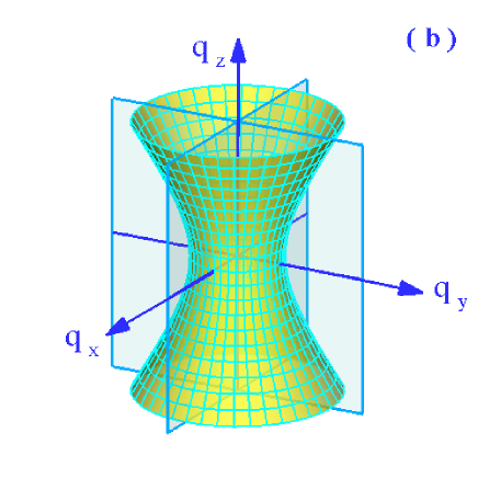
In the next step, we wish to discuss the interesting anisotropic metamaterial, which never exist in the conventional anisotropic crystal. For the special case, if the anisotropic parameters satisfy the following conditions:
| (21) |
the wave-vector surfaces of E- and H-polarized waves are the same single-sheeted hyperbola as shown in Fig. 1(b). In this case
| (22) |
It should be mentioned that in quasiisotropic metamaterial, E- and H-polarized waves have the same wave-vector surface and exhibit the same propagation properties Luo2006b . While in this special case E- and H-polarized waves exhibit the opposite amphoteric refraction, even if the two polarized waves have the same wave-vector surface. We thus conclude that this special kind of anisotropic metamaterial can not be regarded as a quasiisotropic one.
Because of the importance in potential application, we want to mention the splitting angle between E- and H-polarized waves. Because the actual direction of light is defined by the time-averaged Poynting vector, the splitting angle between E- and H-polarized waves can be defined as
| (23) |
The opposite amphoteric refraction suggest that a large splitting angle can be obtained. The large beam splitting angle and splitting distance are preferable for practical applications, especially in the field of optical communication systems.
IV Straight Lines dispersion relations
In this section, we are interested in studying the case that two
single-sheeted hyperboloid intersect each other. There exist two
types which can be formed from combinations
of the material parameter tensor elements.
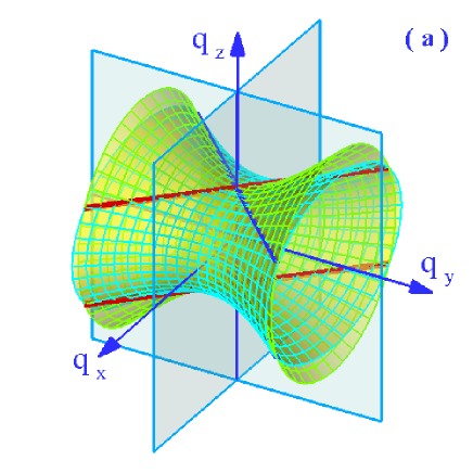
Type I. The anisotropic parameters satisfy the conditions:
| (24) |
the two single-sheeted hyperboloid have the same revolution axis
as shown in Fig. 2(a).
Here we choose the revolution axis coincide with axis.
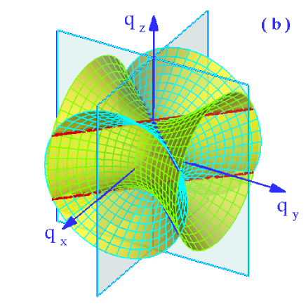
Type II. The anisotropic parameters satisfy the conditions:
| (25) |
the revolution axes of the two single-sheeted hyperboloid are perpendicular to each other as depicted in Fig. 2(b).
In general, the two wave-vector surfaces intersect in a curve. Under introducing the condition , the two single-sheeted hyperboloid can intersect in four straight lines
| (26) |
Obviously, from Eq. (26), we can find four straight lines locate at the plane with the azimuth angles
| (27) |
Now, we want to enquires: Whether E- and H-polarized waves exhibit the same propagation feature or the special plane can be regarded as a plane axes.
In order to explore the wave propagation in the special plane, we illustrate the dispersion relation in three dimensions. The incident wave vector incident with an azimuth angle from free space into the anisotropic metamaterial. Then the incident angle of light is given by
| (28) |
where , , and . The refraction angles of the transmitted wave vector in anisotropic metamaterial can be found by
| (29) |
where . From the boundary conditions at the interface , the tangential components of the wave vectors must be continuous, i.e., . Based on the dispersion relations and the boundary conditions, the refraction angle of wave vector can be obtained.
In addition to the refraction of a wave incident at the interface between free space and the anisotropic metamaterial, we are also interested in the magnitude of the reflection coefficient, so we must solve the boundary conditions at the interface. For E-polarized incident waves, the fields in free space are composed of the incident and reflected waves, having the form
| (30) |
| (31) |
where and are the reflection coefficients of the and components, respectively. Matching the boundary conditions for each component at gives the complex field in the anisotropic metamaterial
| (32) |
where and are the transmission coefficients of the and components, respectively. Based on the boundary conditions yield the equations
| (33) |
We next require continuity of the transverse component of the magnetic field, which can be found from the electric field by use of the Maxwell curl equation combined with the general constitutive relation
| (34) |
Equating the and components of the magnetic vectors corresponding to the incident, reflected, and transmitted fields, we have
| (35) |
For E-polarized incident waves, combining Eq. (35) with Eq. (33), we can obtain the following expressions for the reflection and transmission coefficients for and components
| (36) |
| (37) |
Similarly, the reflection and transmission coefficients of H-polarized waves can be obtained as
| (38) |
| (39) |
After the reflection and transmission coefficients are determined, the energy current density of the refracted waves can be obtained. From the boundary condition , we can obtain two possibilities for the refracted wave vector. Energy conservation requires that the component of transmitted Poynting vector must propagate away from the interface, for instance:
| (40) |
| (41) |
Then the signs of and can be determined easily. The corresponding Poynting vectors should be drawn perpendicularly to the dispersion contour. Since , and always have the opposite signs as can be seen from Eqs. (40) and (41). Therefore E- and H-polarized waves exhibit different values of wave vectors, even if the two polarized waves have the same dispersion relation.
Finally we want to discuss wave propagation in the special plane where the azimuth angle . In this special plane, both E- and H-polarized exhibit the same straight lines dispersion relation as shown in Fig. 2. For propagation in the direction of the optic axes, there is only one value of wave vector and, consequently, only one phase velocity. There are, however, two independent directions of polarization Yariv1984 ; Born1999 . Clearly, there do not exist the direction where E- and H-polarized waves will exhibit the same wave vector (or phase velocity). We thus conclude that this special plane can not be regarded as a plane axes, if we think the conventional concept of optical axis is still correct.
V Conclusion
In conclusion, we have investigated the properties of wave propagation in the anisotropic metamaterial with single-sheeted hyperboloid dispersion relation. At the interface associated with such anisotropic metamaterial, we found E- and H-polarized waves exhibit opposite amphoteric refraction characteristics, such that one polarized waves are positively refracted whereas the other polarized waves are negatively refracted. We have explored the wave propagation in the unique anisotropic metamaterial, in which both E- and H-polarized waves have the same single-sheeted hyperboloid or straight lines dispersion relation. We expect many potential device applications can be fabricated based on the special properties of waves propagation discussed above. They can, for example, be used to construct very efficient polarization-independent isolators, optical switches, and polarization splitters.
Acknowledgements.
H. Luo and W. Shu are sincerely grateful to Professor A. Lakhtakia for many fruitful discussions. This work was supported by projects of the National Natural Science Foundation of China (Nos. 10125521 and 10535010) and the 973 National Major State Basic Development of China (No. G2000077400).References
- (1) A. Yariv, P. Yeh: Optical Waves in Crystals, (John Wiley and Sons, New York, 1984)
- (2) M. Born, E. Wolf: Principles of Optics, (Cambridge, New York, 1999)
- (3) V.G. Veselago: Sov. Phys. Usp. 10, 509 (1968).
- (4) D.R. Smith, W.J. Padilla, D.C. Vier, S.C. Nemat-Nasser, S. Schultz: Phys. Rev. Lett. 84, 4184 (2000).
- (5) J.B. Pendry: Phys. Rev. Lett. 85, 3966 (2000).
- (6) R.A. Shelby: D.R. Smith, S. Schultz, Science 292, 77 (2001).
- (7) C.G. Parazzoli, R.B. Greegor, K. Li, B.E C. Koltenba, M. Tanielian: Phys. Rev. Lett. 90, 107401 (2003).
- (8) A.A. Houck, J.B. Brock, I.L. Chuang: Phys. Rev. Lett. 90, 37401 (2003).
- (9) I.V. Lindell, S.A. Tretyakov, K.I. Nikoskinen, S. Ilvonen, Microw. Opt. Technol. Lett. 31, 129 (2001).
- (10) L. Hu, S.T. Chui: Phys. Rev. B 66, 085108 (2002).
- (11) D.R. Smith, D. Schurig: Phys. Rev. Lett. 90, 077405 (2003).
- (12) L. Zhou, C.T. Chan, P. Sheng: Phys. Rev. B 68 115424 (2003).
- (13) H. Luo, W. Hu, X. Yi, H. Liu, J. Zhu: Opt. Commun. 254, 353 (2005).
- (14) N.H. Shen, Q. Wang, J. Chen, Y.X. Fan, J. Ding, H.T. Wang, Y. Tian, N.B. Ming: Phys. Rev. B 72, 153104 (2005).
- (15) H. Luo, W. Shu, F. Li, Z. Ren: Opt. Commun. 267, 271 (2006).
- (16) H. Luo, W. Hu, W. Shu, F. Li, Z. Ren: Europhysics Letters 74, 1081 (2006).
- (17) R.A. Depine, M.E. Inchaussandague, A. Lakhtakia: J. Opt. Soc. Am. A 23, 949 (2006).
- (18) R.A. Depine, M.E. Inchaussandague, A. Lakhtakia: J. Opt. Soc. Am. B 23, 514 (2006).