BEPCII/BESIII Upgrade and the Prospective Physics
Abstract
The Status of BEPCII/BESIII upgrade is described, BEPCII is designed to reach a luminosity of at c. m. energy of 3.89GeV, and BESIII detector is fully rebuilt. The project is on track and is progressing well. The machine and detector are expected to commission together at the late half of 2007, and start to take some engineer run end of 2007 or beginning of 2008.
I Introduction
Beijing Electron Positron Collider (BEPC) started data taking in 1989, and they were upgraded in 1996, and the upgraded detector is called BESII besiidetector . BES had taken data until the April of 2004, many results have been obtained using the data samples collected at J/, , and the scan data from 2.0 to 5.0 GeV.
After more 15 years data taking, the machine and detector are no more competitive to produce first grade physics at this energy region, especially after CESR reduced its energy to the -charm energy region. After several years of preparation, the Chinese Government gave a green light to begin the BEPCII/BESIII upgrade at the end of 2003.
BEPCII is a two rings machine built in the existing tunnel, electrons and positrons are circulated in separate rings and only collider in the interaction point, multi-bunches and micro-beta are used to increase the machine luminosity. Super-conducting cavities and super-conducting quadruples are used. The Linac has to be upgraded also to increase its energy and currents, especially to meet the needs to inject the positions to the ring in a reasonable short time.
The detector has to be totally rebuilt, with a 43 layers small-cell main drift chamber (MDC), a time of flight (TOF) system, and an electro-magnetic calorimeter Made of CsI, a super-conducting magnet with a field of 1 tesla, and resistive plate chambers (RPC) are inserted in the magnet yoke to serve as the muon counters.
The whole project is scheduled to complete in 2008, with a goal that the luminosity of the machine should reach at the end of 2008.
II BEPCII
The main parameters of machine parameters are listed in Table I.
| Energy Range | 1-2.1 GeV |
|---|---|
| Optimum energy | 1.89 GeV |
| Luminosity | at 1.89 GeV |
| Injection | Full energy inject.: 1.55-1.89 GeV |
| Position Injection 50 mA/min | |
| Synchrotron mode | 250 mA at 2.5 GeV |
| Parameters | Design | Achieved | BEPC |
| Beam energy (GeV) | 1.89 | 1.89();1.89() | 1.55 |
| Current | 40 | 63 | 4 |
| Current | 500 | 500 | 50 |
| Repetition rate (Hz) | 50 | 25-50 | 25 |
| emit. (mm-mrad) | 1.60 | 0.93 (1.89 GeV) | 1.70 |
| emit. (mm-mrad) | 0.20 | 0.30 (1.89 GeV) | 0.58 |
| energy spread (%) | 0.50 (1.89 GeV) | 0.8 | |
| energy spread (%) | 0.55 (1.89 GeV) | 0.8 |
To increase the injection energy and current to the rings, the Linac has been upgrades, the main systems are new acceleration tubes, new klystrons and modulators, new positron source, new electron gun and increase the beam repetition rate to 50 Hz, modified vacuum system, and other relevant modifications. The Linac has been debugged and tuned, some of the performances have already reached the designed values, and now the main efforts are to understand the operation of the Linac and to make the running condition to be stable and install the phase control system. The achieved performances of the Linac are listed in Table II.
| Parameters | Unit | BEPCII | BEPC |
| Operation energy | GeV | 1.0-2.1 | 1.0-2.5 |
| Injection energy() | GeV | 1.55-1.89 | 1.3 |
| Circumference(C) | m | 237.5 | 240.4 |
| -function at IP(/) | cm | 100/1.5 | 120/5 |
| Tunes() | 6.57/7.61/0.034 | 5.8/6.7/0.02 | |
| Hor. natural emittance() | mm-mr | 0.14 at 1.89 GeV | 0.39 at 1.89 GeV |
| Dampling time () | 25/25/12.5 at 1.89 GeV | 28/28/14 at 1.89 GeV | |
| RF frequency () | MHZ | 499.8 | 199.533 |
| RF voltage per ring () | MV | 1.5 | 0.6-1.6 |
| Number of bunches | 93 | 21 | |
| Bunch spacing | m | 2.4 | 240.4 |
| Beam current colliding | mA | 910 1.89GeV | 235 1.89 GeV |
| Bunch length() | cm | 1.5 | 5 |
| Impedance | 0.2 | 4 | |
| Crossing angle | mrad | 0 | |
| Beam lifetime | hrs. | 2.7 | 6-8 |
| Luminosity1.89 GeV | 100 | 1 |
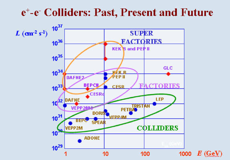
The main parameters of the storage rings are listed in Table III. BEPCII storage rings have the following main systems: the super-conducting rf cavities and their power supplies and control system; the beam pipes; the magnets and their power supplies; the kickers; the beam instrumentations; the vacuum system; the control system. The dipole magnets of old ring are modified to be put in the outer ring. Up till now, most of the hardware devices are delivered, and the pieces not on site yet are scheduled to be delivered on time. The current plan is to assemble all the ring hardware pieces except the super-conducting quadruple magnets, for which more time is needed to get them tested and to measure the field with detector magnet together. The plan is to commission the whole rings without the quadruples first and provide some beam time for synchrotron use, then the quadruples are to be moved in the beam line to be tested together with other systems, after certain performance goals are met, especially certain amount of current should be reached so to verify the large currents can be run with certain luminosity and reasonable backgrounds to the detector, before the detector moves in to be debugged together with the machine. The machine and detector are expected to be commissioned together at the late half of 2007, and start to take some engineer run end of 2007 or beginning of 2008. The performance of BEPCII will be among the 2nd generation of colliders, as shown in Figure 1.
III BESIII Detector
The BESIII detector besiiidetector is a completely new detector. Figure 2 shows the schematic of BESIII detector.
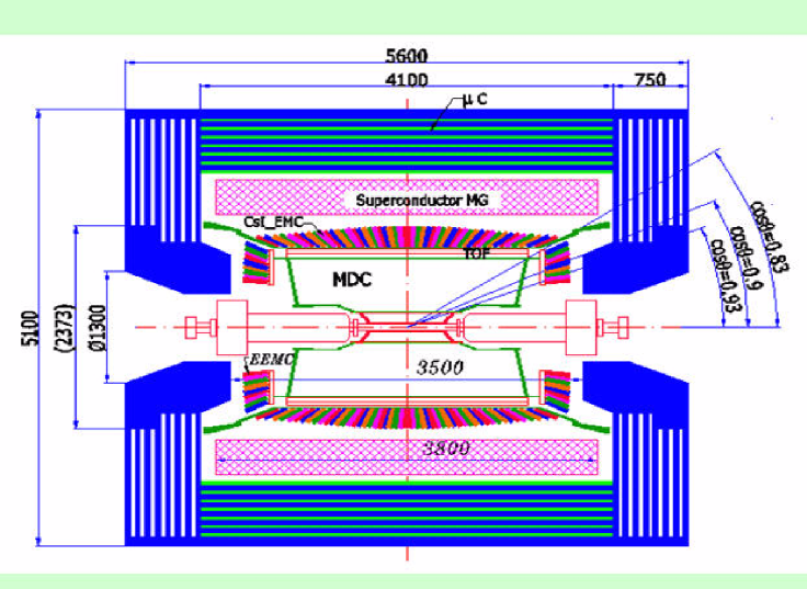
The beam pipe is made of two layers of Be pipes, with the thickness of 0.8 mm and 0.5 mm respectively, and a cooler is passed through between the pipes to take out the heat caused by the beams. MDC is the most inside detector component, it has 43 sense wires from inside to outside. To make room for the machine super-conducting magnet, the endplates are made from a cone shaped central section and a slightly inclined outer plate. The endplates are manufactured with the average hole accuracy better than 25 . Small cell structure is used with a half width of cell to be 6 mm for inner layers, and 8.1 mm for outer layers. The sense wire is made of 25 tungsten, the field wire is made of 110 gold plated Al. Totally there are about 28K wires. The gas chosen is used by CLEOIII. All the wires have been strung and the tension and the leakage current of all wires are measured and satisfy the requirements. The electrons readout system adopts CERN HPTDC to measure the drift time, the prototype electron system is tested, and the performances meet the design requirements. A small chamber was tested in the KEK beam line, and the space resolution and dE/dx resolution are satisfactory. The expected chamber performances are, wire resolution to be better than 130 , and the momentum resolution is expected to better than 0.5% for 1 GeV tracks, two contributions from wire position resolution and multiple scattering are: = and respectively. The outmost sense wire covers a polar angle of = 0.83, and the maximum acceptance is = 0.93, roughly reach 20th sense wire layer. The expected dE/dx resolution is about .
Mounted on the MDC are two layers of TOF counters, each layer has 88 counters with a thickness of 5 cm and the two layers are staggered by half a counter to make a full coverage in the polar angle of = 0.82. There are photo-tubes at both ends of each counter to read the signals. And there are 48 single-layer counters in each side of the endcap region, and the signal is read out only at the inner end. The counters are mounted on the endcap EM calorimeter. BC408 and BC404 scintillators by Bicro are chosen for barrel and endcap respectively. The photo-tubes used are R2490-50 by Hamamatsu. From the test beam, 90 and 100 ps time resolutions are achieved for barrel and endcap respectively, as expected in the design.
Outside of TOF system is a CsI crystal EM calorimeter. The typical crystal has a dimension of in the front face and in the rear face, the length is 28 cm, corresponding to 15 radiation length. There are 5280 crystals in barrel and 960 in the endcap, 480 at each side. Two photo diodes (Hamamatsu S2744-08) with a photosensitive area of 10 mm 20 mm are mounted on the rear face of each crystal to read the lights out. The prototype for readout electronics is tested to have a noise level of 1000 electrons. The expected energy resolution will be for 1 GeV photons. The crystals are made by Crismatec(France), Shanghai Institute of Ceramic and Beijing Hamamatsu. Most of the crystals are delivered and they met the specifications of dimensions, light yield and the radiation hardness. The mechanical structure of the calorimeter is designed such that there are no walls between crystals to reduce the dead material, the crystals are fixed to a support structure by 4 screws. will be flew in the crystal container to maintain the humidity inside, and the front-end electronics will be cooled by water. The EM calorimeter is scheduled to be assembled around the end of 2006.
Outside of EM calorimeter is the super-conducting magnet, its designed field is 1.0 tesla. The magnet uses the inner winding technique with the coil wound inside a Al support cylinder which in turn cooled by liquid He circled in the pipe welded on the outer surface of the support cylinder, the Al stabilized NbTi/Cu coil is made by Hitachi company, with the nominal operating current of about 3700 A, which has a stored energy of about 10 MJ. The field in the MDC volume has an uniformity of better than 5, the field will be measured with an accuracy of better than 0.25. The magnet is in the stage of testing the value box and after that to install the valve box with the magnet coil assembling, then the cryogenic system will be connected to the magnet and the whole magnet will be cooled and tested.
The return yoke is also served as the absorber of the muon detectors. The active muon detector is the Resistive Plate Chamber (RPC), there are 9 layers muon chambers in the barrel and 8 layers in the endcap, with two orthogonal strip readout alternatively layer by layer. The muon chambers are inserted in the steel slots in the yoke. The special feature of the RPC made in China is that there is no linseed oil used in the gap of RPC. The gas used is . All the RPC are installed in the yoke and the efficiencies and the dark currents measured are quite good, to the same level as those RPC with linseed oil used in other experiments.
The whole detector weights about 800 tons. And the detector hall will be air-conditioned, to control the temperature at , and the humidity below .
The electronics and trigger use pipelined arrangement, with a trigger latency of 6.4 s. The trigger will use TOF, MDC and Muon information to make decisions. The simulation shows that good (almost 100) efficiency and a good background rejection can be achieved. The maximum trigger rate will be at J/ energy with a total trigger rate of about 4000 Hz. At this energy, the good event rate will be about 2000 Hz. The DAQ bandwidth will be about 50 Mbytes per second. The readout system is based on VME. The offline analyzes package is under development, the preliminary version for event simulation and reconstruction is ready, the calibration codes and physics analyzes code are being worked on. The offline system will go through another two releases to get the package tested before the real data are taken.
The main designed detector performances are listed in Table IV, a comparison with CLEOc is made. Hopefully, some of the parameters may be better than designed.
| Detector | BESIII | CLEOc |
|---|---|---|
| = 130m | 90m | |
| MDC | (1 GeV) = 0.5 | 0.5 |
| = 6-7 | 6 | |
| EMC | (1 GeV) = 2.5 | 2.2 |
| = 0.6cm/ | 0.5cm/ | |
| TOF | = 100-110ps | Rich |
| counter | 9 layers | — |
| magnet | 1.0 tesla | 1.0 tesla |
IV Prospective Physics
The rich physics topics at this energy region will require BESIII to take the data at J/, , , and some energy point for , also data at threshold and some scan data to measure hadronic cross-section in this energy region will be collected. The yearly yield of events are listed in Table V for different energy points the data are to be taken.
| Resonance | Energy(GeV) | Peak Lum. | Physics Cross | Nevents/yr |
| Section(nb) | ||||
| J/ | 3.097 | 0.6 | 3400 | |
| 3.670 | 1.0 | 2.4 | ||
| 3.686 | 1.0 | 640 | ||
| 3.770 | 1.0 | 3.6 | ||
| 3.770 | 1.0 | 2.8 | ||
| 4.030 | 0.6 | 0.32 | ||
| 4.140 | 0.6 | 0.67 |
The new X(1835) and other near threshold enhancements recently observed at BES will be studied with 100 times more data, X(3872) and states observed at 3940 MeV and 4260 MeV in other experiments may be studied in details. There are more scalars existed in this energy region to be accommodated in naive quark model, these states will be thoroughly studied.
The , and can be studies with large statistics. The puzzle will be studied with more decay channels and with better accuracy and different models can be tested and developed to explain the mechanism behind that.
A data sample at are to be taken, it will enable the measurements related with D decays to reach a new precision, for example, the , can be measured to a statistic accuracy of about , with a data sample of total accumulated luminosity of 20 . And the mixing and CP violation will be searched and studied. With huge data samples, the systematic errors should be well understood, and a lot of analyzes will adopt partial wave analyzes (PWA) to fully understand the decay dynamics. Efforts are being made and will be strengthened.
Right now, BES Collaboration has about 18 Chinese institutes and universities, and physicists from United State, Japan, Germany, Sweden and Russia have joined. BES welcomes new collaborators to join this exciting research project, which should last for at least 10 years. A conference called Charm2006 will be held in Beijing in June this year to discuss the physics potentials at BESIII and a US-CHINA workshop on the BESIII collaboration will be held right afterwards. All interested persons are welcome.
References
- (1) J. Z. Bai et al. (BES Collaboration), Nucl. Instrum. Methods Phys. Res. Sect. A 552,344(2005).
- (2) Preliminary Design Report of the BESIII Detector, IHEP-BEPCII-SB-13.