Generation of Traveling Surface Plasmon Waves by Free-Electron Impact
Abstract
The injection of a beam of free 50 keV electrons into an unstructured gold surface creates a highly localized source of traveling surface plasmons with spectrum centered around 1.8 eV. The plasmons were detected by a controlled decoupling into light with a grating at a distance from the excitation point. The dominant contribution to the plasmon generation appears to come from the recombination of d-band holes created by the electron beam excitation.
Surface plasmon polaritons (SPPs) are coupled transverse electromagnetic field and charge density oscillations which propagate along the interface between a conductor and a dielectric medium. The main feature of the SPPs that currently attracts exploding attention is that they are strongly localized, making them favored candidates as information carriers in applications such as high-density broadband interconnections and signal processing Barnes:2003 ; Zayats:2005 .
The excitation of SPPs is usually performed by optical means, and since SPPs do not couple to light illumination at flat metal-vacuum interface, the energy coupling is achieved using gratings or prism matching schemes. Surface plasmon waves can also be generated in corrugated tunnelling junctions Kirtley:1980 . Unfortunately, these techniques do not easily allow for a high localization of the SPP source, as being essential for nanophotonic devices. Discontinuities of a plasmon waveguide, such as a nanoparticle, nanowire Krenn:2003 or nanoscale aperture of a nearfield optical probe Sonnichsen:2000 , may be used for a more localized launch of plasmon waves. However, these coupling techniques are cumbersome, and they do not always allow for easy repositioning of the plasmon source. Ritchie predicted that the electron bombardment of a metal film could lead to the excitation of surface plasmons Ritchie:1957 , and evidence of this was later observed in aluminium films by electron energy loss spectroscopy Powell:1959 and by light emission of silver grating surfaces Teng:1967 . Recently an evidence of propagating surface plasmon modes was observed in the spatial distribution of optical emission on microscale gold corral under electron excitation in the scanning tunneling microscope Beversluis:2003 .
In this Letter, we report on the first demonstration of direct excitation of SPPs by injection of a beam of free electrons on the unstructured metal interface, creating a plasmon source potentially with nanoscale localization, which may be easily and dynamically repositioned anywhere in a plasmonic device, for example in a SPP waveguide.
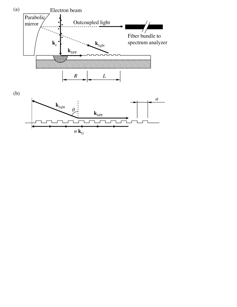
A fast electron penetrating a metal film loose a fraction of its energy by exciting plasmons on the metal surface, as illustrated in Fig. 1. In our experiments the SPPs were excited in gold films by a focused electron beam of a scanning electron microscope. The SPPs were decoupled into light by a microscopic grating manufactured on the metal surface, with the uncoupled light being collected by a parabolic metal mirror into an optical multichannel spectrum analyzer consisting of a Jobin-Yvon C140 spectrograph and a liquid nitrogen cooled CCD array, in a geometry as illustrated in Fig. 1(a). The samples were thick gold films which incorporated deep gratings with a period of . The gratings were specifically designed for decoupling of light predominantly in the backward direction.
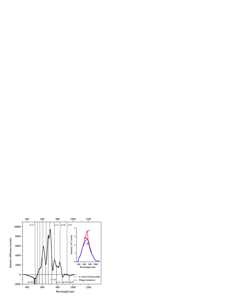
The evidence of SPP generation by electron beam excitation was seen in two series of experiments. In the first series we compared light emission from the unstructured gold surface with emission from the gold grating. In this case the experiments were performed using scanning mode of the microscope, with a scan area of about . Optical emission of the unstructured gold surface was clearly seen in our experiments. This is a combination of the -band fluorescence, as previously seen in femtosecond photoluminescent experiments Beversluis:2003 , transient radiation of the collapsing dipoles formed by the electrons approaching the metal surface and their oppositely charged mirror image, and the fluorescence of any residual contaminants on the sample. These mechanisms of emission create a smooth spectrum centered at about , shown as line B in the inset of Fig. 2. The emission spectrum of unstructured gold surface was identical to that of the grating parallel the direction towards the collection mirror. However, when the grating was oriented with its ribs perpendicular to the direction to the mirror, the emission was stronger than of the unstructured gold and its spectrum showed some pronounced modulations. Such a difference in detection of emission is explained by the directionality of the decoupling of the travelling SPPs, which only in the latter case are decoupled into light directed towards the detection system.
A grating fabricated on a metal surface facilitates decoupling of light by providing a wave vector mismatch equal to an integer multiple of the grating vector where is the grating period, as illustrated in Fig. 1(b). Only SPPs of certain frequencies are decoupled by the grating in the direction of the detector, at an angle of approximately degrees, as determined by the geometry of setup. This decoupling is described by the kinematic equation
| (1) |
where is a positive integer describing the diffraction order. In the spectrum shown in Fig. 2, the peak wavelengths at which optimum detection of the decoupled radiation occur are indicated with the corresponding diffraction orders , as calculated from Eq. (2). One can clearly see that peaks in the emission spectrum indeed to a high degree coincide with the predicted values for efficient SPP emission. One also can also observe several dips in the emission spectrum and even wavelengths at which the emission from the grating is less intense than that of unstructured gold. This is believed to result from the modification of the plasmon dispersion by the grating at frequencies given by the Bragg condition
| (2) |
where is a positive integer describing the resonance order. Here is the complex-valued permittivity of gold. Corresponding wavelengths of Bragg resonance are in Fig. 2 presented for various values of , indicating that the SPPs at Bragg resonance are either badly coupled to light or their generation by the electron beam is inhibited by the grating.
The second experimental series aimed to demonstrate the generation of travelling SPP waves on an unstructured metal surface, their propagation and controlled decoupling into light by a grating. In these experiments we studied the dependence of the optical emission as function of distance between the excitation point and the grating edge. This series of experiments was performed using spot mode of excitation, with a spot diameter of about . The large spot size was used in order to allow higher beam current and more intense peaks in decoupled light. The spectrum of the signal detected by placing the electron beam at the edge of the grating facing the mirror is essentially the same as in the scanning mode over the grating, with the only difference that the negative values in the differential spectrum seen in Fig. 2 at about , and do not appear, corroborating with the idea that they are indeed relevant to the Bragg frequencies.
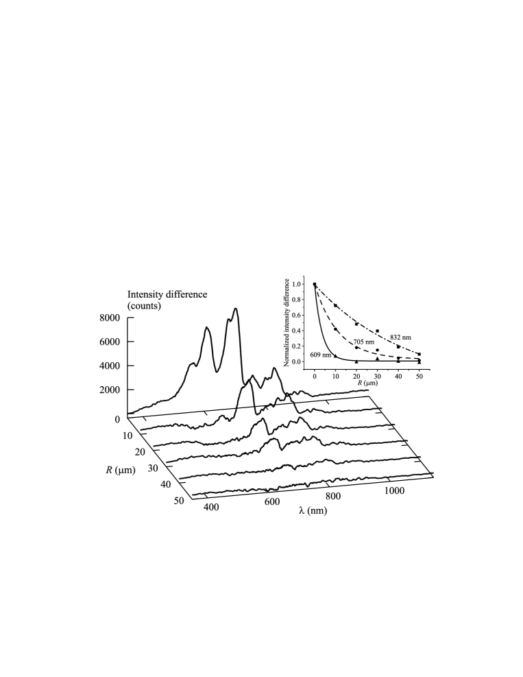
As the point of excitation is moved away from the grating, the spectrum gradually changes and the SPP component of emission diminishes, as shown in Fig. 3. This graph illustrates that SPP waves corresponding to different parts of the emission spectrum decay with different pace (see inset into Fig. 3). For a point-like source, the in-plane plasmon intensity is proportional to . Due to our detection system, collecting light in a range of in-plane azimuthal angles, this leads to an dependence for the decoupled and detected signal, giving the experimental attenuation lengths , , and . Indeed, plasmons corresponding to the vacuum wavelength of shall be strongly attenuated by losses in gold with damping length rapidly increasing towards the infrared part of the spectrum. This is also what we find in our experimental data. However, our experimentally derived energy attenuation lengths are somewhat shorter than predicted from the formula and the bulk values of the dielectric coefficient of gold. This is explained by imperfections and granulation of the gold surface, providing an additional source for plasmon scattering losses.
All our observations, in particular the wavelength dependent decay of the emission spectrum with the distance between the excitation point and the grating, prove that electron beam excitation indeed provides a source of SPPs. The plasmon emission spectrum largely correlates with the spectrum of unstructured gold emission as shown in graph B of Fig. 2, suggesting that the dominant contribution to SPP generation comes from the recombination of -band holes created by electron beam excitation Dulkeith:2004 , rather than from direct scattering of free electrons Ritchie:1957 . Therefore it appears that plasmon emission spectrum, as the spectrum of luminescence are strongly connected to the energy separation between holes and the Fermi surface near and points roughly at (), and (), correspondingly Beversluis:2003 .
From our experimental data, one can obtain an estimate of the order of magnitude of the total power of the SPP source at the point of excitation. At the electron beam current of , or equivalently electrons per second, we detect plasmon-related photons at the rate of across the spectrum. As a rough estimate of the quantum efficiency of our light decoupling, collection and detection system, we obtain about . This corresponds to a SPP source with a total power of , generating SPPs per second at the point of excitation. The corresponding probability for a single electron to excite a SPP is then , which is consistent with Refs. Ritchie:1957 ; Farrell:1958 .
In conclusion, we have shown that electron beam excitation of an unstructured gold surface provides a potentially highly localized source of propagating surface plasmons. This may be the technique of choice for creating the high density of plasmons necessary for demonstrating nonlinear regimes of SPP propagation, and also for achieving a high density of plasmons in the active media of spaser applications Bergman:2003 .
This work was supported by grants from the Engineering and Physical Sciences Research Council (UK), the Office of Basic Energy Sciences, U.S. Department of Energy, and the US National Science Foundation. Stimulating discussions with Javier Garcia de Abajo and useful references provided by Mathieu Kociak are also acknowledged.
References
- (1) W. L. Barnes, A. Dereux and T. W. Ebbesen, Nature 424, 824 (2003).
- (2) A. V. Zayats, I. I. Smolyaninov, A. A. Maradudin, Phys. Rep. 408, 131 (2005)
- (3) J. R. Kirtley, T. N. Theis, and J. C. Tsang, Appl. Phys. Lett. 37, 435 (1980); N. Kroó, Z. Szentirmay and J. Félszerfalvi, Phys. Lett. A 81, 399 (1981).
- (4) J. R. Krenn et al., J. of Microscopy 209, 167 (2003).
- (5) C. Sönnichsen et al., Appl. Phys. Lett. 76, 140 (2000)
- (6) R. H. Ritchie. Phys. Rev. 106, 874 (1957))
- (7) C. J. Powell and J. B. Swan, Phys. Rev. 115, 869 (1959); P. E. Batson and J. Silcox, Phys. Rev. B 27, 5224 (1983).
- (8) Y. Teng and E. Stern, Phys. Rev. Lett. 19, 511 (1967); D. Heitmann, J. Phys. C: Solid State Phys. 10, (1977).
- (9) M. R. Beversluis, A. Bouhelier, and L. Novotny, Phys. Rev. B 68, 115433 (2003).
- (10) E. Dulkeith et al., Phys. Rev. B 70, 205424 (2004).
- (11) R. A. Farrell, Phys. Rev. 111, 1214 (1958).
- (12) D. J. Bergman and M. I. Stockman, Phys. Rev. Lett. 90, 027402 (2003).