Feasibility of a storage ring for polar molecules in strong-field-seeking states
Abstract
We show, through modeling and simulation, that it is feasible to construct a storage ring that will store dense bunches of strong-field-seeking polar molecules at 30 m/s (kinetic energy of 2K) and hold them, for several minutes, against losses due to defocusing, oscillations, and diffusion. The ring, 3 m in diameter, has straight sections that afford access to the stored molecules and a lattice structure that may be adapted for evaporative cooling. Simulation is done using a newly-developed code that tracks the particles, in time, through 400 turns; it accounts for longitudinal velocity changes as a function of external electric field, focusing and deflection nonlinearities, and the effects of gravity. An injector, decelerator, and source are included and intensities are calculated.
pacs:
29.20 Dh, 41.75.Lx, 33.80.Ps, 39.90.+d, 33.55.BeI Introduction
To date, all gaseous quantum condensates have been produced by evaporative cooling of confined atoms. Confinement is necessary to thermally isolate the particles from the warmer environment and long confinement times are necessary because the evaporative cooling process can take tens of seconds.
Strong magnetic field gradients have been used to confine neutral paramagnetic molecules weinstein and electric-field gradients have been used to confine neutral polar molecules in electrostatic traps bethlem00 and in toroidal storage rings crompvoets01 ; crompvoets04 . In addition, polar molecule confinement in a synchrotron storage ring has been modeled nishimura03 .
All of these methods use molecules or atoms in weak-field-seeking states, whose binding energy decreases in the field. These states are not the lowest energy state and are therefore subject to collisional relaxation. In alkali atoms, the relaxation rates from the stretched hyperfine levels () is small. But in magnetically trapped paramagnetic molecules volpi02 and in electrically confined polar molecules bohn01 ; kajita01 ; kajita02 ; avdeenkov02 , the relaxation rate can be large enough to prevent achieving the confinement time needed for evaporative cooling.
Collisional relaxation will be absent for polar molecules in their lowest rotational state. This ground state is strong-field-seeking, as are all rotational states in the limit of strong electric field. The technical challenges of storing molecules in a strong-field-seeking state have not been previously addressed. The major challenge is focusing these molecules because electrostatic lenses can focus strong-field-seeking molecules in only one transverse plane while defocusing in the other. Therefore alternating-gradient focusing is required.
For experiments on molecules in strong-field-seeking states, a storage ring has some useful features not generally found in traps. The ring has a beam geometry with field-free regions accessible to experiments, and it can simultaneously store many bunches of particles producing a large flux of molecules.
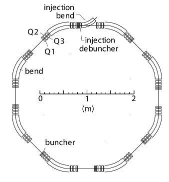
In this paper we show, by modeling and simulation, that it is feasible to construct a storage ring (Fig.1) that will store a symmetric-top molecule (methyl fluoride) in the state, at a kinetic energy of 2 K (30 m/s), and by extension other molecules and velocities. In the storage ring, bunching electrodes hold the molecules in a string of short bunches. The molecules are calculated to be stable against losses due to defocusing, oscillations, and diffusion for over two minutes. We also model a decelerator for slowing the molecules to 30 m/s, and an injector for loading the storage ring.
A storage ring in which the density of the molecules in a bunch is allowed to vary around the ring, can provide a mechanism for evaporative cooling. Regions of high density speed the thermalization of the molecules. In regions of low density the molecules can become spatially separated due to their velocity spread allowing the hottest molecules to be removed.
II Forces Due to Electric Field Gradients
II.1 Focusing and Deflection Using Multipole Fields
A brief description of focusing and deflecting a beam of molecules using electrostatic multipole fields is given below. Additional details of beam transport and focusing of molecules in strong-field-seeking states, with specific application to methyl fluoride in the state, may be found in Kalnins et al. kalnins02 .
The guide field in a storage ring for molecules in strong-field-seeking states must provide all the functions, such as focusing, bending, and bunching, that are used in a ring for charged particles but with forces that arise from gradients of the magnitude of the electric field.
In a pure quadrupole or sextupole field, the total electric field increases radially and the force on a molecule, in a strong-field-seeking state, is away from the centerline in all transverse directions. Therefore a dipole component must be added to remove the double-defocusing, and obtain focusing in one transverse direction while still defocusing in the other. The force on a molecule is given by the gradient of its Stark potential energy, :
| (1) |
where is the magnitude of an external field.
The Stark energy of the molecular level is in general a nonlinear function and is described for methyl fluoride in the rotational state in Ref. kalnins02 . In the limit of large , where is the molecule’s electric dipole moment.
The transverse ( horizontal, vertical) electric multipole potential used to bend and focus a molecule is:
| (2) |
where is the dipole field strength, and and are the relative quadrupole and sextupole component strengths.
For the Stark energy in the high-field limit, the forces to second order are:
| (3) |
We see that a combined dipole and sextupole () field lens will focus in one plane, while defocusing in the other. To deflect the molecule we must add a quadrupole () component. This also defocuses the beam in the direction and stronger sextupole () strengths are needed OurPAC2003paper .
To obtain net focusing in both transverse planes, the lenses are arranged in a sequence with gradients alternating in sign ( for -focusing and 0 for -focusing).
II.2 Other Effects
When a molecule in a strong-field-seeking state enters the field of an electrode pair it is accelerated longitudinally, and upon exiting the field it is decelerated. Also, the fringing field is stronger away from the midplane and this causes a net defocusing force in the direction of the electric field. Between successive sets of electrodes, this unwanted defocusing is reduced if the dipole fields are of the same polarity and strength.
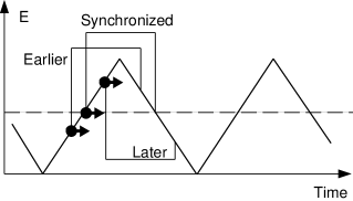
Longitudinal bunching, as in a charged-particle ring, requires a pulsed field. The field is ramped in a sawtooth or sine-wave form and the time-dependent acceleration is the net difference between the fields when entering and when exiting.
The effect of gravity is small but not negligible for 30 m/s molecules in this ring. The vertical orbit will be distorted and an orbit correction must be applied.
II.3 Equations of Motion
The equations of motion of a molecule in the ring are obtained from the Hamiltonian:
| (4) |
where is the Stark energy, g is the acceleration due to gravity, and is the kinetic energy which in a bend region is:
| (5) |
where and are the transverse momenta, is the angular momentum and is the bend radius. In straight sections the last term is replaced by the square of the longitudinal momentum, .
The longitudinal variation of the Stark energy at the ends of electrodes (treated here as a step function) adds or subtracts from the kinetic energy, the change in longitudinal velocity being about 10.
Vertical defocusing in a fringe field is derived from the longitudinal variation of the field on the midplane and to lowest order is:
| (6) |
III Storage Ring Design
III.1 Molecule and Energy
The principles and techniques we use apply to all polar molecules in strong-field-seeking states. We choose methyl fluoride (CH3F) as our reference molecule because it is a nearly symmetric rotor with a large electric dipole moment of = C-m (1.84 D). It has a moderate rotational constant of cm-1 and a simple level structure with a rotational ground state. The rotational constant is large enough to limit the number of rotational levels populated in the beam from a jet-source but still small enough to allow for a large Stark effect at moderate electric fields. Methyl fluoride is also a gas at room temperature.
The velocity of 30 m/s (kinetic energy of about 2K) is low enough to make for a compact ring, yet keep small the effects of gravity.
III.2 Ring Lattice
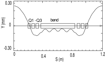
Long straight regions free of focusing electrodes make the stored beam accessible for experiments and give space for injection and extraction. Molecules, in order to drift through the straight section without loss, must have only small divergences and therefore a large beam width. In a bending region, we need strong deflecting forces to minimize the bend radius for overall compactness. These strong forces call for a small beam width to avoid nonlinearities. To make the transition (match) from straight sections to arc sections, triplets (Q1, Q2, Q3) of focusing lenses are placed at the ends of the straight sections, as shown in Fig. 1.
In each of the eight bend regions, there are five electrode pairs; each has a combined dipole and quadrupole field to provide the strong deflecting force. To this is added a sextupole component, the gradient of which alternates in sign.
The electrode parameters are given in Table 1 where Q are focusing elements and BF and BD are combined bend and focusing elements. Each arc is a series of BF and BD elements: BF+BD+BF+BD+BF.
In this sequence of lenses with alternating gradients, the molecules execute oscillatory transverse motions. The parameters of BF and BD are chosen such that the phases of these horizontal and vertical motions each advance through an angle of 2 in each octant of arc. The parameters of Q1, Q2 and Q3 are varied to find values that produce large dynamic aperture and momentum acceptance. The decapole coefficient, of Q2, which adds the term to the potential Eq(2), is introduced to reduce the nonlinearity of Q2 focusing where the beam is at it’s largest. For longitudinal confinement with many short bunches, we use eight bunchers in the ring; each has a short uniform field that is pulsed in time as illustrated in Fig. 2.
Molecules with different energies have their closed orbits radially separated in the arcs and perhaps elsewhere in the ring. If this dispersion of orbits is present at a buncher, the energy change from the buncher produces a shift in the orbit and an increment in the radial oscillation. This is called synchro-betatron coupling and to avoid growth of radial oscillation amplitude, the dispersion of orbits must be made zero at the bunchers. With the phases of the vertical and horizontal motions advancing through an angle of in each octant, as noted above, the dispersion becomes zero at all eight buncher locations.
| (MV/m) | (cm) | (m-2) | (m-3) | (m-5) | |
|---|---|---|---|---|---|
| Q1 | 3.0 | 3.34 | 0 | 2000 | 0 |
| Q2 | 4.0 | 3.71 | 0 | -2000 | -1.28106 |
| Q3 | 4.0 | 2.85 | 0 | 2000 | 0 |
| BF | 7.85 | 4.00 | -10.55 | -2296 | 0 |
| BD | 7.85 | 4.00 | -10.55 | 2343 | 0 |
III.3 Numerical Modeling and Simulation
The lattice parameters (Table 1) are found by numerical calculations using a newly-developed simulation code that tracks the particles in time (rather than in longitudinal position) to account for the longitudinal velocity changes as a function of the external field. The tracking code includes the effects of nonlinearities, gravity and the longitudinal kick at the bunchers. The effect of each fringe field (Eq. 6) in every element has been integrated and replaced by a vertically defocusing thin lens. The parameters in Table 1 result in the ring performance listed in Table. 2 and shown in Figures 3 and 4.
| Parameter | Value |
| Circumference (m) | 9.850 |
| Circulation period (s) | 0.3121 |
| Velocity in free space (m/s) | 30.0 |
| Symmetry of the ring | 8 |
| Bending radius (m) | 0.60 |
| Long straight section (m) | 0.40 |
| Beta function∗ (m) | 0.274 |
| (m) | 0.596 |
| Dispersion∗ (m) | 0.0 |
| Betatron tune | 13.368 |
| 10.398 | |
| Dynamic aperture∗ (mm) | 1.75 |
| (mm) | 3.50 |
| Acceptance (mm - mr) | 11 |
| (mm - mr) | 21 |
| Momentum acceptance () | 1.2 |
| Number of longitudinal buckets | 203 |
| ∗At the center of straight sections |
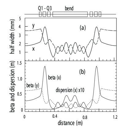
The beta functions and the horizontal dispersion are shown in Fig. 3b. Small beta functions in the bends produce a smaller beam profile, allowing the bend elements to be stronger and the beam to occupy the most linear region of the elements. The straight sections are designed to be free of horizontal dispersion to avoid synchro-beta coupling at the bunchers.
If uncorrected, the vertical closed orbit displacement caused by gravity is 2.6 mm and is large enough to cause loss of the circulating beam. The orbit is corrected by displacing Q2 by 0.24 mm downward to produce upward kicks. The resulting vertical orbit distortion shrinks to 0.26 mm as shown in Fig. 5 and is no longer a problem.
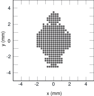
With this orbit correction, the dynamic aperture for 400 turns, at the center of a straight section, is about 2 mm by 3 mm half-width as shown in Fig. 4. This dynamic aperture corresponds to acceptances of 11 mm-mr horizontal and 21 mm-mr vertical, as listed in Table 2. The resulting beam size is shown in Fig. 3a. The momentum acceptance, calculated by the multi-particle tracking simulation, is which is equivalent to an energy acceptance of 45 mK.
IV Decelerated Beam
IV.1 Decelerator
To reduce the velocity from the 310 m/s at the source to 30 m/s requires many stages of deceleration by pulsed electric fields in a long linear array. At each of the 139 decelerating stages, a bunch of molecules enters a set of parallel electrodes when the field is zero; the field pulses on and the molecules lose kinetic energy equal to as they exit the electrodes.
Our decelerator design differs in almost every way from previous designs bethlem02a ; tarbutt04 . A decrease in the strength of the electric field while the bunch exits the electrodes provides longitudinal restoring action that prevents the bunch lengthening due to velocity spread maddi99 . The lengths of successive electrodes decreases as the velocity and spacing of the bunches decreases.
Interspersed between the pulsed parallel electrodes are alternating-gradient lenses to confine the molecules transversely. Their overall focusing action must be stronger in the plane of the electric fields to counter the defocusing from fringe fields. The major parameters of the decelerator are summarized in Table 3. Details of decelerator design will be published later.
| Parameter | Value |
|---|---|
| Velocity at source (m/s) | 310 |
| Velocity at exit (m/s) | 30 |
| Velocity spread at exit (%) | 2 |
| Length of bunch at exit (mm) | 10 |
| Emittances at exit, x and y (mm-mr) | 30 |
| Electrode gap (mm) | 7 |
| Decelerating field at entrance (MV/m) | 9 |
| Decelerating field at exit (MV/m) | 4.5 |
| Length of last decel. electrode (mm) | 24 |
| Length of decelerator (m) | 19.6 |
| Number of decel. electrodes | 139 |
IV.2 Injector
To inject the beam, we need a bend electrode that can pulse on or off in the time between buckets in the ring. This allows us to store multiple (up to 203) bunches in the ring. The deflecting electrode (Fig.1) is part of a transport line that transforms the pulse leaving the decelerator to match the orientation of the transverse acceptances of the ring at the point of entry onto the closed orbit of the ring. The deflecting electrode is actually an array of bend electrodes with radius 0.6 m, similar to a bend section in the ring. A horizontal phase advance of in this bend, avoids a net dispersal of molecules that are within the % velocity spread.
In passage along the line, the velocity spread of % lengthens the bunch and a debuncher at the point of injection (Fig 1) brings 90% of the bunch within the % longitudinal momentum acceptance of the ring.
IV.3 Source and Intensity
We calculate the intensity based upon a pulsed jet source with 1% methyl fluoride seeded in xenon carrier gas, using the equations in Miller miller88 and verified against seeded xenon jet source performance reported in the literature crompvoets01 ; crompvoets04 ; gupta99 . Xenon’s high mass (133) produces much slower beams (310 m/s from a room-temperature reservoir) than do light carrier gases, resulting in a shorter (19.6 m) decelerator.
The bunch intensity is determined by the source flow rate, the state population, the velocity distribution and the acceptances. A source orifice of 1 mm diameter and reservoir pressure of Pa (500 Torr) will produce an intense cold beam with a peak intensity of molecules sr-1 s-1, a longitudinal velocity spread of 7.2 m/s FWHM, and less than 1% clusters. We estimate the methyl fluoride J = 0 rotational state fraction to be 30%. In an apparatus with a finite pumping speed, this peak intensity is possibly only by using a pulsed jet source operating with a small duty cycle. The short widely-spaced beam pulses entering the decelerator (which become more closely spaced after deceleration) require a duty cycle of less than one percent for a 100 Hz pulse rate. This would allow all 203 buckets in the ring to be filled in 6.4 turns.
The transverse and the longitudinal emittances (units of m2 s-1) of a bunch of molecules are unchanged in passing through the deceleration processlambertson04 from the source to their injection in the storage ring. Therefore the fraction of molecules from the source that enters the ring is the product of the ratios of ring acceptances to source emittances. In the transverse directions, the beam from the source has mm spatial extents and mr angular divergences; then the horizontal and vertical acceptances of the storage ring (Table 2) of 11 mm-mr and 21 mm-mr respectively, result in of the molecules being transversely accepted. Longitudinally, one second of beam from the source is 310 m long and has a velocity spread of m/s. The storage ring will accept m/s in a 10-mm long bunch, which is of the source longitudinal emittance.
Combining these nunbers and acounting for the 90% acceptance of the storage ring from the injector yields an intensity of molecules/bunch. Bunches could be injected into the storage ring singularly or in large numbers. With a maximum of 203 stored bunches there would be nearly 1011 molecules circulating in the storage ring and a flux of 2.5 1011 molecules/s. Each bunch would have a density of about 3 109 molecules/cm3 in the long straight sections, and higher in the bends.
V Acknowledgments
The authors acknowledge and thank Richard Gough and David Robin for their enthusiastic encouragement, and Swapan Chattopadhyay and Ying Wu for early contributions to the storage ring work. Work supported by the Director, Office of Science; Office of Basic Energy Sciences, and Office of High Energy and Nuclear Physics, U.S. Department of Energy, under Contract No. DE-AC03-76SF00098.
References
- (1) J. D. Weinstein, R. deCarvalho, T. Guillet, B. Friedrich and J.M. Doyle, Nature 395, 148 (1998).
- (2) H.L. Bethlem, G. Berden, F.M.H. Crompvoets, R.T. Jongma, A.J.A. van Roij, and G. Meijer, Nature 406, 491 (2000).
- (3) F.M.H. Crompvoets, H.L. Bethlem, R.T. Jongma, and G. Meijer, Nature 411, 174 (2001).
- (4) F.M.H. Crompvoets, H.L. Bethlem, J. Küpper, A.J.A. van Roij and G. Meijer, Phys. Rev. A69, 063406 (2001).
- (5) H. Nishimura, G. Lambertson, J. G. Kalnins, and H. Gould, Rev. Sci. Instr. 43, 3271 (2003).
- (6) A. Volpi and J.L. Bohn, Phys. Rev. A65, 052712 (2002).
- (7) J. L. Bohn, Phys. Rev. A63, 052714 (2001).
- (8) M. Kajita, T. Suzuki, H. Odashima, Y. Moriwaki, and M. Tachikawa, Jpn. J. Appl. Phys. 40, L1260 (2001).
- (9) M. Kajita, Eur. Phys. J. D20, 55 (2002).
- (10) A.V Avdeenkov and J.L. Bohn, Phys. Rev. A66, 0052718 (2002).
- (11) J.G. Kalnins, G. Lambertson, and H. Gould, Rev. Sci. Instr. 73, 2557 (2002).
- (12) H. Nishimura, G. Lambertson, J.G. Kalnins, and H. Gould, IEEE Proc. of PAC 2003, 1837 (2002).
- (13) H.L. Bethlem, A.J.A. van Roij, R.T. Jongma and G. Meijer, Phys. Rev. Lett. 88, 133003 (2002).
- (14) M.R. Tarbutt, H.L. Bethlem, J.J. Hudson, V.L. Ryabov, V.A. Ryzhov, B.E. Sauer, G. Meijer, and E.A. Hinds, Phys. Rev. Lett. 92, 173002 (2004).
- (15) J.A. Maddi, T.P. Dinneen, and H. Gould, Phys. Rev. A60, 3882 (1999).
- (16) D.R. Miller, in Atomic and Molecular Beam Methods, edited by G. Scoles (Oxford University Press, New York, 1988), Vol. 1, p. 14.
- (17) M. Gupta and D. Herschbach, J. Phys. Chem. 103, 10670 (1999).
- (18) G. Lambertson, private communication, 2004.