Magneto-Dielectric Substrates in Antenna Miniaturization: Potential and Limitations
P.O. Box 3000, FI-02015 TKK, Finland
2Institute for Theoretical and Applied Electromagnetics, 13/19 Izhorskaya ul. Russian Academy of Sciences, 125412 Moscow, Russia)
Address for correspondence:
Pekka Ikonen
Radio Laboratory, Helsinki University of Technology
P.O. Box 3000, FI-02015 TKK, Finland
Fax: +358-9-451-2152
E-mail: pekka.ikonen@tkk.fi
Abstract
In the present paper we discuss antenna miniaturization using magneto-dielectric substrates. Recent results found in the literature reveal that advantages over conventional dielectric substrates can only be achieved if natural magnetic inclusions are embedded into the substrate. This observation is revised and the physical background is clarified. We present a detailed discussion concerning magnetic materials available in the microwave regime and containing natural magnetic constituents. The effects of magnetic dispersion and loss are studied: constraints on the microwave permeability are used to estimate the effect of magnetic substrates on the achievable impedance bandwidth. Microwave composites filled with thin ferromagnetic films are considered as a prospective antenna substrate. We calculate the impedance bandwidth for a -patch antenna loaded with the proposed substrate, and challenge the results against those obtained with conventional dielectric substrates. It is shown that the radiation quality factor is strongly minimized with the proposed substrate even in the presence of realistic losses. Estimates for the radiation efficiency are given as a function of the magnetic loss factor.
Key words: Patch antenna, magneto-dielectrics, ferromagnetic film, frequency dispersion, quality factor, miniaturization
1 Introduction
It is well known that the impedance bandwidth of electrically small antennas is roughly proportional to the volume of the antenna in wavelengths. This means that when the antenna is downsized the impedance bandwidth suffers. However, the trend in the communications industry is towards smaller size devices, thus, efficient antenna miniaturization is a clear necessity. One of the most common miniaturization techniques is the loading of the antenna volume with different materials [1]–[4]. Most traditionally, high permittivity dielectrics have been used to decrease the physical dimensions of the radiator, e.g. [5, 6, 7]. Common problems encountered with high permittivity substrates include e.g. the excitation of surface waves leading to lowered radiation efficiency and pattern degradation, and difficulties in the impedance matching of the antenna. Recently, artificial high-permeability materials working in the microwave regime [8]–[16] have been proposed to decrease the size and/or to enhance the impedance bandwidth properties of microstrip antennas [17]–[28].
According to the work of Hansen and Burke [17], inductive (magnetic) loading leads to an efficient size miniaturization of a microstrip antenna. When the material parameters of the antenna substrate are dispersion-free, and 1, a transmission-line (TL) model for a normal -patch antenna predicts that the impedance bandwidth is retained after miniaturization [17]. Ikonen et al. [28] conducted extensive study on the effect of frequency dispersion of artificial111A mixture of electrically small, resonating metal unit cells is used to enhance the magnetic effect. magneto-dielectric substrates on the impedance bandwidth properties of the loaded antenna. It was analytically and experimentally shown that due to frequency dispersion of the substrate the obtained radiation quality factor always exceeds obtained using conventional dielectric substrates. This conclusion is valid when the voltage and current distribution on the antenna element are not changed, and the static permeability equals unity. According to the Rozanov limit [29] for the thickness to bandwidth ratio of radar absorbers, the thickness of the absorber at microwave frequencies (with a given reflectivity level) is bounded by the static value of of the absorber. Discussion presented in [28] revealed that the static properties of the magneto-dielectric substrate play an important role also in antenna design. It was shown that a substrate obeying the modified Lorentzian type dispersion rule and static permeability exceeding unity was advantageous in terms of minimized over some frequency range.
The present work has two main goals: 1) give a simple physical explanation on the advantages of magnetic materials in antenna miniaturization by considering the actual measurable quantities on the antenna element, namely the resonant current and voltage amplitudes. Moreover, using a lumped element model we explicitly reveal the effect of the static permeability and frequency dispersion. The presently obtained results are generalized by revising the main results obtained in [28]. 2) Present discussion concerning magnetic materials available in the microwave regime and containing natural magnetic inclusions. Microwave composites filled with thin ferromagnetic films [30] are introduced as prospective antenna substrates. The effects of magnetic dispersion and loss are studied. Using a TL-model we calculate the impedance bandwidth properties of a patch antenna loaded with the proposed substrate and a conventional dielectric substrate. It is shown that in terms of minimized radiation quality factor the proposed substrate outperforms conventional dielectric substrates. Estimates for the radiation efficiency are given as a function of the magnetic loss factor.
The rest of the paper is organized in the following way: in section II we revise the effect of the antenna substrate on . Section III presents discussion concerning feasible magnetic materials and discusses constraints on the achievable microwave permeability. The calculated impedance bandwidth characteristics are presented in Section IV. The work is concluded in Section V.
2 The effect of antenna substrate on
2.1 Physical insight using dispersion-free material parameters
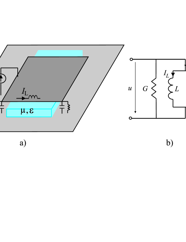
It is known that a magnetic substrate is advantageous in microstrip antenna miniaturization if the material parameters of the substrate are lossless and dispersion-free, e.g. [17]. To give a physical explanation on this phenomenon let us consider a resonant -patch antenna operating at a fundamental angular frequency . Moreover, assume the antenna to be filled with hypothetical dispersion-free and lossless materials characterized by , Fig. 1. The impedance behavior of the antenna can be approximated with the behavior of a parallel-resonant circuit in the vicinity of . Using the lumped element representation we get for the quality factor of the antenna
| (1) |
where represents the losses in the resonator (in this case mainly due to radiation), and and are the inductance and the capacitance of the empty resonator. From (1) we draw the known observation: with a fixed an increase in the inductance (permeability of the filling material) lowers the quality factor, whereas increase in the capacitance (permittivity) increases the quality factor leading to a narrow impedance bandwidth.
A heuristic idea of the physics behind this observation can be received by considering the amplitude of the current oscillating in the circuit. At the resonance this amplitude is typically very strong. When thinking of the antenna structure presented in Fig. 1a. the strong current flowing in the antenna element (and in the ground plane) creates a flux which only contributes to stored energy, since radiation happens at the edges of the patch. Moreover, if one leaves the ends of the patch free from the filling (as is done in Fig. 1a.) the filling has only a very small effect on the radiation conductance. So intuitively one should try to decrease the amplitude of the oscillating current as much as possible. Increase in will lower the impedance of the capacitor, moreover at the same time we must decrease (to keep fixed) and this further leads to decreased impedance level. Thus, it will be easy for the oscillation to build up in the circuit. The same observation will be seen by considering the stored energy in the circuit at the resonance
| (2) |
where is the amplitude of the current through the inductor and is the amplitude of the voltage over the capacitor. Usually a patch antenna is fed with a fixed voltage source, thus, is fixed. We see from (2) that increase in leads to strongly increased stored energy, since we must at the same time decrease the value of to keep the resonant frequency fixed. On the other hand, by increasing we can reduce and both factors decrease the stored energy.
2.2 The effect of static permeability and frequency dispersion
Due to frequency dispersion of artificial magneto-dielectric substrates conventional dielectric substrates are always better in terms of retained impedance bandwidth in antenna miniaturization [28]. The effect of frequency dispersion has a very fundamental nature, yet this effect is often neglected. A common misbelief is that by selecting the operational frequency of the antenna closer to the substrate resonance the bandwidth is more effectively retained since Re is larger. However, the closer one lies to the substrate resonance, the steeper is the gradient of the dispersion curve.
To explain the effect of static permeability and frequency dispersion let us assume that the antenna shown in Fig. 1a. is filled with a magneto-dielectric material obeying the modified Lorentzian type dispersion in :
| (3) |
Above is the static permeability, is the amplitude factor (), is the undamped angular frequency of the zeroth pole pair (the resonant frequency of the medium), and is the loss factor. The modified Lorentzian type dispersion rule is a commonly accepted model for dense arrays of split-ring resonators and other similar structures (in this case ), e.g. [9, 13, 16]. Certain composites containing natural magnetic constituents, e.g. composite substrates containing thin ferromagnetic films [30], can be modeled using the general Lorentzian model. Here we study for the sake of clarity the effect of static permeability using (3) since the general Lorentzian model reduces to (3) at low frequencies. In (3) natural magnetism is described by , however, (3) is not in a general case applicable with natural magnetics (as will be explained in the next section). In the vicinity of the magnetic resonance the effective permittivity of a dense array of split ring resonators is weakly dispersive, and can be assumed to be constant. With composites containing ferromagnetic films the effective permittivity can also be considered dispersion-free over a wide frequency range. Thus, we assume , where is the effective permittivity of the substrate.
Usually a magnetic (magneto-dielectric) substrate is utilized well below the substrate resonance (e.g. [19, 27, 28]) and we assume that . For the sake of simplicity we assume that losses in the magnetic material are negligible in the vicinity of ()222We discuss later in more detail situations when the loss contribution cannot be neglected., in addition to this the loss tangent for the permittivity is assumed to be very small. With the aforementioned assumptions the inductance reads
| (4) |
The resonant condition becomes
| (5) |
and we can readily solve the squared angular resonant frequency
| (6) |
Dispersion in the material slightly changes the resonant frequency compared to the case when there is no dispersion. When the antenna operates well enough below the material resonance the dispersion is weak and the angular resonant frequency can be expanded into Taylor series:
| (7) |
With the assumptions described earlier the susceptance of the resonator reads (in the vicinity of the antenna resonance)
| (8) |
The quality factor of the resonator becomes
| (9) |
which can be further polished:
| (10) |
Important observations can be made from (10): first of all, if there is no dispersion () the quality factor reduces to the well known static result given by (1). From causality we know that every passive and linear material is inevitably dispersive (and lossy), thus in reality . Eq. (10) shows the strong effect of the static permeability which was noticed already in [28]: if the magnetic material only increases the quality factor, no matter if the value of Re at the operational frequency of the antenna. is necessary to compensate the negative effect of frequency dispersion.
2.3 Relative radiation quality factor
The above derivation based on the lumped element model can be generalized to some extend by considering a resonator whose spectrum is concentrated near a certain frequency (the discussion partly follows the discussion presented in [28]). Again we assume that the resonator is filled with low-loss materials . Note that here we consider a general case of frequency dispersion, the low-loss assumption is the only assumption that we make concerning the dispersion law in the material. The known expression for the time-averaged energy density of electromagnetic fields reads [31, 32]
| (11) |
Above and are the amplitudes of the electric and magnetic fields. The energy stored in the resonator can be found by integrating over the volume of the resonator. From (11) we see that increase in both and will increase the stored energy. In addition to this, the increase of stored energy due to frequency dispersion is also explicit in (11).
Let us consider a resonant -patch antenna having length , width , and height . The antenna element lies on top of a large, non-resonant ground plane. The radiation quality factor was derived in [28]
| (12) |
Here is the characteristic admittance of the patch segment [33], and is the radiation conductance. If the material parameters are dispersion-free given by eq. (12) is the same as considered e.g. in [17]. In practise a patch antenna is commonly fed using a short and narrow feed line to ease the impedance matching. For the discussion on additional stored energy due to the feed strip, please see [28].
When studying antenna miniaturization using novel antenna substrates, conventional dielectric substrates are often used as a reference substrate. Usually with high accuracy the permittivity of the substrate can be regarded dispersion-free over a wide frequency range. Let us in the reference case fill the volume under the antenna element with a dielectric substrate offering the same size reduction []. The ratio between the radiation quality factors becomes
| (13) |
Eq. (13) is the key formula allowing a proper comparison between the impedance bandwidth characteristics of rectangular333The aforementioned steps of derivation can be repeated for different antenna geometries. patch antennas loaded with conventional dielectric substrates and novel antenna substrates. It can be used when the following criteria are met:
-
1.
Both substrates have small losses.
-
2.
The reference substrate does not possess any magnetic response and the permittivity can be considered dispersion-free.
-
3.
The voltage and current distribution remain unchanged, i.e. both substrates fill the volume under the patch element uniformly.
Formula for the energy density [eq. (11)] holds strictly only when the absorption due to losses can be neglected. If losses in the material can not be neglected near the frequency of interest, it is not possible to express energy density in terms of material permittivity and permeability functions [31], pp. 28–30. One has to have knowledge about the material microstructure, and this leads to a modification of the energy density expression [34, 35]. With artificial magnetics dispersion is normal and loss contribution small at frequencies . Thus, in this case it is justified to neglect the loss contribution. However, for many microwave materials containing natural magnetic constituents the dispersion is anomalous also well below the material cutoff frequency. In this case the second term in the right part of (10) is negative, and dispersion decreases the quality factor. However, losses and dispersion appear together according to the low-frequency Kramers-Kronig relation
| (14) |
Losses in the substrate degrade the radiation efficiency of the antenna and increase the radiation quality factor: by definition the radiation efficiency is the ratio between unloaded quality factor 444The quality factor in (10) is the unloaded quality factor since only radiation losses are assumed. and , thus, the radiation quality factor is calculated as
| (15) |
Using the cavity theory can also be estimated as
| (16) |
where and are the magnetic and dielectric loss tangents, respectively. As was shown in [36] the use of anomalous dispersion is not promising due to associated additional losses. In a practical situation the effect of anomalous dispersion is negligible compared to the loss effect, and therefore the effect of anomalous dispersion is not considered in the analysis of next section.
3 Prospective magnetic materials for microwave frequencies: revision of the key properties
Microwave performance of most magnetic materials containing natural magnetic constituents is due to the ferromagnetic resonance. When modeling these materials the general Lorentzian type dispersion law can be used for the complex permeability:
| (17) |
where is the static permeability, is the ferromagnetic (angular) resonant frequency, and is an empirical damping factor. The complex permeability is close to the static permeability at frequencies up to the ferromagnetic resonant frequency , which can be considered as the permeability cutoff frequency. The microwave permeability is large when both and are high. However, it is well known that these values are related tightly to each other: higher leads to lower , and vice versa. For most bulk magnetic materials the relation is established by Snoek’s law:
| (18) |
where is the saturation magnetization and GHz/kOe. In magnetic materials, both and are dependent on the effective anisotropy field of the material, which, in turn, depends on the composition, as well as on the manufacturing process, treatment, small admixtures, etc. The right part of (18) is a function of the saturation magnetization, the value of which is determined by the composition only. For this reason, Snoek’s law is conventionally used for estimating the microwave performance of the material. Within the limits imposed by Snoek’s law, the static permeability and resonant frequency can frequently be changed within a wide range by certain technological means.
In some occasions, instead of (18), the relation between the static permeability and resonant frequency has the form
| (19) |
Eq. (19) is valid for thin ferromagnetic films with in-plane magnetic anisotropy [37], and in this case and is the largest component of permeability. The other case is related to hexagonal ferrites [38] with , and are out-of-plane and in-plane anisotropy fields respectively, and the material is assumed to be isotropic. Only these two classes of magnets are known to obey (19). Eq. (19) permits higher static permeability compared to (18) with the same resonant frequency, provided that is not too high. The value in the right part of eq. (19) is conventionally referred to as Acher’s constant of the material, . However, this constant is typically derived from the linear frequency rather than from the angular frequency. Therefore the right part of (19) is equal to , where is expressed in GHz2.
In hexagonal ferrites, typical values of Acher’s constant are not higher than 100 to 200 GHz2 [38, 39]. This means that with the resonant frequency GHz the static permeability can be as high as 10 to 20. For a discussion of hexagonal ferrites for miniaturization of microstrip antennas, see [27]. Ferromagnetic films with in-plane anisotropy may have much larger Acher’s constants due to higher saturation magnetization. For example, for iron kG and GHz2. However, with iron films having thickness larger than approximately half a micrometer the microwave performance is deteriorated by the effect of eddy currents. In addition to this, the out-of-plane component of magnetization appears in thick films and also makes the microwave magnetic performance of the film worse.
To apply ferromagnetic films as a bulk material, which is needed e.g. if the films are utilized as microstrip antenna substrates, film laminates may be used [30]. The laminates can be made using sputtering process with a thin polymer substrate followed by stacking the sputtered substrates together to obtain a bulk laminate. It is shown that for bulk laminates ( is the volume fraction of magnetic components in the laminate) in (19) [40]. For sputtered microwave laminates made of iron, the film thickness must not be larger than 0.3 mcm, and the thickness of substrate may be as low as 10 mcm [40]. Then % vol. and GHz2, a value which is about the same as that with hexagonal ferrites. If several magnetic layers separated by non-magnetic interlayers are sputtered onto a polymer substrate, the volume fraction may be increased by a factor of order of the number of layers [40]. With this method the potentially obtained microwave permeability values are the highest possible among all magnets.
In some respect film laminates have advantages over ferrites. Ferrites are ceramic materials, hence they are not easily machined (which can be necessary for accurate adjusting of the resonant size). Laminates consist mainly of polymeric substrate, thus, they are easily machineable and may be shaped with high precision. Ferrites have a specific weight of approximately 5 g/cm3, while polymer-based film laminates weight about 1 g/cm3. For low-frequency antennas whose volume may be dozens of cubic centimeters, this difference may be essential. Moreover, hexagonal ferrites have inherently high permittivity ( and larger [39]), a feature which is not typically desirable in antenna miniaturization in the view of retained impedance bandwidth. For film laminates the permittivity is anisotropic: the component perpendicular to film layers, which is the dominant component e.g. if the laminates are used in microstrip antenna miniaturization, is as low as approximately . Ferrites can be used as composites with ferrite powder to diminish the above drawbacks, but in this case and decreases correspondingly [39]. On the other hand, the film laminates require more complex technology and can therefore be more expensive. Another thing which has to be remembered when using thin ferromagnetic films in antenna miniaturization is the conductivity along the film layers. The effect occurs due to fringing electric fields and is seen as an increased effective dielectric loss tangent. However, with patch antennas the effect can be reduced by leaving a short section of empty space (length of the empty space about the height of the patch) near the radiating edges, and/or using patterned films.
The most important issue deteriorating the microwave performance of the discussed materials is the effect of the quality factor of ferromagnetic resonance. Most practically realizable materials have a low quality factor for the ferromagnetic resonance, so that in eq. (18) and starts to decrease at frequencies already well below the resonance. When , the absorption peak and, correspondingly, the region of stronger frequency dispersion are located in the vicinity of rather than in the vicinity of . In this case, the permeability cutoff frequency is governed by Snoek’s law (18) rather than by Acher’s law (19) [41].
When the proposed materials are used in antenna miniaturization the most important effect of magnetic loss is the rapid decrease of the radiation efficiency with increased frequency. From the low-frequency asymptote of the Lorentzian dispersion law we arrive to the following bounding relation between the operating frequency of the loaded antenna , the ferromagnetic resonance , the damping factor , the radiation quality factor , and the radiation efficiency :
| (20) |
Above, the magnetic loss tangent is estimated based on the Lorentzian dispersion law, in actual magnets additional loss mechanisms appear for low frequency loss which may increase noticeably the loss tangent at very low frequencies compared to the resonance [44]. From the literature, fundamental restrictions concerning the quality factor of the ferromagnetic resonance are not available. In actual samples, the quality factor is dependent on the inhomogeneity of the sample, magnetic structure, etc. Most of the reported data on demagnetized polycrystalline samples reveal wide-spread resonance curves. However, values of that are as low as 0.2 can be found for both ferromagnetic films [42, 43] and hexagonal ferrites [27] (for all three data the resonant frequency is 1.6 GHz). Generally, if , , , and the Acher’s constant are given, the ferromagnetic resonant frequency must be larger than
| (21) |
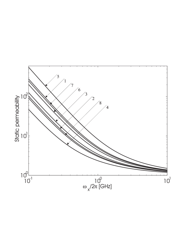
with . Eq. (21) is derived by first solving from (19) and substituting this into (20). By solving from (19) and substituting this into (20) one can study what kind of static permeability values are possible given that and are known. The general expression is somewhat cumbersome, but in Fig. 2 we present values for the static permeability as functions of the operating frequency of the antenna . and vary according to Table 1, in every case. It is seen from Fig. 2 that the obtainable static permeability values decrease dramatically as the operating frequency of the antenna increases. If the antenna operates in the GHz range the obtainable permeability values are rather moderate.
| Curve no. | Curve no. | ||||||
|---|---|---|---|---|---|---|---|
| 1 | 100 | 0.3 | 20 | 2 | 100 | 0.5 | 20 |
| 3 | 100 | 0.3 | 30 | 4 | 100 | 0.5 | 30 |
| 5 | 200 | 0.3 | 20 | 6 | 200 | 0.5 | 20 |
| 7 | 200 | 0.3 | 30 | 8 | 200 | 0.5 | 30 |
4 Calculated impedance bandwidth properties with the proposed substrate
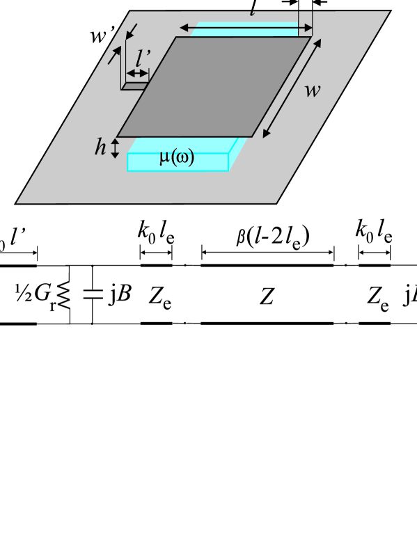
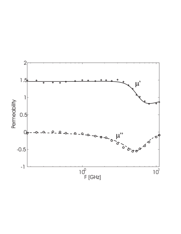
In the present section we model a strip fed -patch antenna lying on top of a non-resonant ground plane using a TL-representation. A schematic illustration of the antenna and the equivalent TL-representation are shown in Fig. 3. The formulation of the model is introduced in detail in [28]. The above described layered substrate containing thin ferromagnetic films is chosen as the studied antenna substrate. The dispersion of of the substrate is given in Fig. 4. The permittivity component perpendicular to film layers is assumed to be dispersion-free and is estimated . Moreover, we load the antenna volume with a reference dielectric substrate offering the same size reduction.
We have chosen 580 MHz for the center frequency of the miniaturization scheme. This frequency has strongly increasing practical importance since it corresponds to the center frequency of the Digital Video Broadcast (DVB) system [46]. As discussed in the previous section, for the practical utilization of composite substrates containing natural magnetic inclusions the frequency should not be too high due to rapidly increasing losses. For comparison, a demonstration for the applicability of a substrate containing sheets of Z-type hexaferrite was conducted at 277 MHz [19].
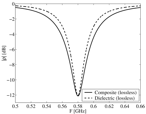
4.1 Lossless substrate
We start the analysis by calculating the impedance bandwidth properties when the antenna is loaded with lossless substrates. We see that at 580 MHz . The value for the relative permittivity of the reference substrate is found to be . The dimensions of the loaded patches are the following: mm, mm, mm. Feed strip width is used to tune the quality of coupling [47] in different loading scenarios. We use a dB matching criterion to define the impedance bandwidth. The corresponding voltage wave standing ratio . To allow a proper comparison between the impedance bandwidth characteristics, has been tuned to by varying .
| Loading | ||||
|---|---|---|---|---|
| Composite | 5.06 | 26.5 | 100 | 26.5 |
| Dielectric | 3.68 | 36.4 | 100 | 36.4 |
Fig. 5 shows the calculated reflection coefficients. The main calculated parameters are gathered in Table 2. The results presented in Fig. 5 and Table 2 agree well with the results given by the analytical expression for the relative radiation quality factor: For the substrate used in the TL-model eq. (13) gives , while the TL-model predicts . It is physically clear that the TL-model predicts a larger : The analytical expression does not take into account the feed strip which can be regarded as an effective inductor [28]. Moreover, due to the feed strip usually a patch antenna operates slightly above it’s parallel resonance. This means that the standing wave pattern in the TL-model is not the “optimal” (parallel resonance) pattern for magnetic loading [28].
The present result validates our previous discussion: The dispersion characteristics of the proposed substrate are advantageous in antenna miniaturization. However, to draw a conclusion on the practical applicability of the proposed substrate, realistic losses have to be taken into account.
4.2 Practically realizable substrate
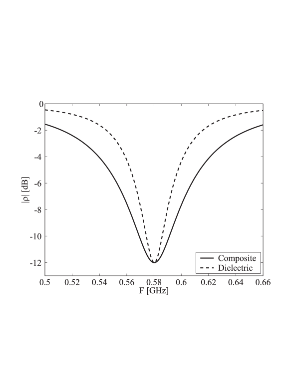
The impedance bandwidth properties are calculated when the antenna is loaded with a practically realizable composite substrate, Fig. 4 [at 580 MHz ]. The relative permittivity of the reference substrate is found to be . The dimensions of the loaded patches are the following: mm, mm, mm. Fig. 6 shows the calculated reflection coefficients. The main calculated parameters are gathered in Table 3. denotes the radiation quality factor obtained using (15), and denotes the radiation quality factor obtained using (16). For the calculation of we calculate the radiation efficiency using the numerical Wheeler Cap method
| (22) |
where is the input resistance at the operational frequency when the radiation conductance is set to zero, and is the input resistance at the operational frequency when the radiation resistance is that given by the TL-model.
Losses in the substrate rather strongly degrade the radiation efficiency. The magnetic loss tangent is at 580 MHz. Compared to the loss tangents of conventional high quality dielectrics the value seems high. However, for comparison, the magnetic loss tangent of a substrate containing sheets of Z-type hexaferrite was reported to be at 277 MHz [19]. Moreover, 580 MHz is a fairly high frequency for the utilization of a substrate containing natural magnetic constituents. Based on the above discussion we consider the radiation efficiency promisingly high. The most important result is that the radiation quality factor is noticeably smaller than with pure dielectrics even in the presence of realistic losses. This means that the antenna miniaturized using the proposed substrate operates closer to the fundamental small antenna limit, thus its size-bandwidth characteristics are better.
| Loading | |||||
|---|---|---|---|---|---|
| Composite | 9.45 | 14.15 | 48.4 | 29.2 | 31.0 |
| Dielectric | 4.94 | 27.08 | 73.8 | 36.7 | 37.2 |
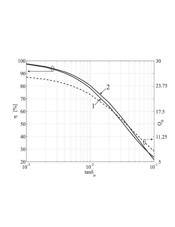
4.3 Estimate for as a function of magnetic loss tangent
There is no theory for the magnetic loss tangent of composites filled with thin ferromagnetic films. Therefore, we assume that with future technology the loss tangent can be brought down. Here we estimate what kind of radiation efficiencies can be achieved with different magnetic loss tangents . We use two different techniques to estimate the efficiency: 1) is calculated using the TL-model and we use (16) to estimate when the loss tangents are known. The radiation efficiency is then calculated using (15). 2) The numerical Wheeler Cap method is used to estimate the radiation efficiency. When calculating the dielectric loss tangent is assumed to be zero for the sake of clarity. With a given the radiation efficiency can conveniently be estimated using (16) and (15) when and are known. The result for the estimation is depicted in Fig. 7.
5 Conclusion
In this paper we have discussed antenna miniaturization using magneto-dielectric substrates. The effect of antenna substrate to the radiation quality factor has been presented. It has been shown that natural magnetic constituents have to be embedded into the substrate in order to gain advantages over conventional dielectric substrates. Detailed discussion has been presented concerning antenna substrates containing natural magnetic inclusions. Moreover, we have introduced a layered substrate containing thin ferromagnetic films as a prospective antenna substrate, and treated limitations for the obtainable permeability values. Using a transmission-line model we have compared the impedance bandwidth properties of antennas loaded with the proposed substrate and a conventional dielectric substrate. The results show that in terms of minimized radiation quality factor the proposed substrate outperforms conventional dielectric substrates. Estimates for the radiation efficiency are given as function of the magnetic loss tangent.
Acknowledgements
We wish to thank Professor Constantin Simovski for useful discussions. K. N. Rozanov and A. V. Osipov are grateful to Russian Foundation for Basic Research for partial support of the work according to grant 05–08–01212.
References
- [1] I. J. Bahl and P. Bhartia, Microstrip antennas, Massachusettes: Artech House, 1980.
- [2] K. R. Carver and J. W. Mink, “Microstrip antenna technology,” IEEE. Trans. Antennas Propagat., vol. AP–29, no. 1, pp. 2–24, 1981.
- [3] D. M. Pozar, “Microstrip antennas,” Proc. IEEE, vol. 80, pp. 79–91, 1992.
- [4] C. A. Balanis, Antenna theory: Analysis and design, New York: John Wiley, 1997.
- [5] R. K. Mongia, A. Ittipiboon, M. Cuhaci, “Low profile dielectric resonator antennas using a very high permittivity material,” Electron Lett., vol. 30, no. 17, pp. 1362–1363, 1994.
- [6] Y. Hwang, Y. P. Zhang, G. X. Zheng, T. K .C. Lo, “Planar inverted F antenna loaded with high permittivity material,” Electron Lett., vol. 31, no. 20, pp. 1710–1712, 1995.
- [7] J. S. Colburn and Y. Rahmat-Samii, “Patch antennas on externally perforated high dielectric constant substrates,” IEEE Trans. Antennas Propagat., vol. 47, no. 12, pp. 1785–1794, 1999.
- [8] M. V. Kostin and V. V. Shevchenko, “Artificial magnetics based on double circular elements,” Proc. Bianisotropics’94, Périgueux, France, pp. 49–56, May 18–20, 1994.
- [9] J. B. Pendry, A. J. Holden, D. J. Robbins, W. J. Stewart, “Magnetism from conductors and enhanced nonlinear phenomena,” IEEE Trans. Microwave Theory Tech., vol. 47, no. 11, pp. 2075–2084, 1999.
- [10] R. Marqués, F. Medina, R. Rafii-El-Idrissi, “Role of bianisotropy in negative permeability and left-handed metamaterials,” Phys. Rev. B, vol. 65, 1444401(–6), 2002.
- [11] M. Gorkunov, M. Lapine, E. Shamonina, K. H. Ringhofer, “Effective magnetic properties of a composite material with circular conductive elements”, European Phys. Journal B, vol. 28, no. 3, pp. 263–269, 2002.
- [12] A. N. Lagarkov, V. N. Semenenko, V. N. Kisel, V. A. Chistyaev, “Development and simulation of microwave artificial magnetic composites utilizing nonmagnetic inclusions,” J. Magnetism and Magnetic Materials, vol. 258–259, pp. 161–166, 2003.
- [13] B. Sauviac, C. R. Simovski, S. A. Tretyakov, “Double split-ring resonators: Analytical modeling and numerical simulations,” Electromagnetics, vol. 24, no. 5, pp. 317–338, 2004.
- [14] J. D. Baena, R. Marqués, F. Medina, J. Martel, “Artificial magnetic metamaterial design by using spiral resonators,” Phys. Rev. B, 69, 014402, 2004.
- [15] C. R. Simovski, A. A. Sochava, S. A. Tretyakov, “New compact and wide-band high impedance surface,” IEEE Antennas Propagat. Soc. Int. Symposium, Monterey, California, vol. 1, pp. 297–300, June 20–25, 2004.
- [16] S. I. Maslovski, P. Ikonen, I. A. Kolmakov, S. A. Tretyakov, M. Kaunisto, “Artificial magnetic materials based on the new magnetic particle: Metasolenoid,” Progress in Electromagnetics Research, vol. 54, pp. 61–81, 2005.
- [17] R. C. Hansen and M. Burke, “Antenna with magneto-dielectrics,” Microwave Opt. Technol. Lett., vol. 26, no. 2., pp. 75–78, 2000.
- [18] S. Yoon and R. W. Ziolkowski, “Bandwidth of a microstrip patch antenna on a magneto-dielectric substrate,” IEEE Antennas Propagat. Soc. Int. Symposium, Columbus, Ohio, pp. 297–300, June 22-27, 2003.
- [19] H. Mossallaei and K. Sarabandi “Magneto-dielectrics in electromagnetics: Concept and applications,” IEEE Trans. Antennas Propagat., vol. 52, no. 6, pp. 1558–1567, 2004.
- [20] ——, “Engineered meta-substrates for antenna miniaturization,” Proc. 2004 URSI Int. Symposium on Electromagn. Theory, Pisa, Italy, pp. 191–193, May 23–27, 2004.
- [21] K. Buell, H. Mosallaei, K. Sarabandi, “Embedded-circuit magnetic metamaterial substrate performance for patch antennas,” IEEE Antennas Propagat. Soc. Int. Symposium, Monterey, California, pp. 1415–1418, June 20–25, 2004.
- [22] M. K. Kärkkäinen, S. A. Tretyakov, P. Ikonen, “Numerical study if a PIFA with dispersive material fillings,” Microwave Opt. Technol. Lett., vol. 45, no. 1, pp. 5–8, 2005.
- [23] M. E. Ermutlu, C. R. Simovski, M. K. Kärkkäinen, P. Ikonen, S. A. Tretyakov, A. A. Sochava, “Miniaturization of patch antennas with new artificial magnetic layers,” 2005 IEEE Int. Workshop on Antenna Technology, Singapore, pp. 87–90, March 7–9, 2005.
- [24] M. E. Ermutlu, C. R. Simovski, M. K. Kärkkäinen, P. Ikonen, A. A. Sochava, S. A. Tretyakov, “Patch antennas with new artificial magnetic layers,” submitted to IEEE Wireless Component Lett. Preprint available at http://arxiv.org/abs/physics/0504075.
- [25] P. Ikonen, S. Maslovski, S. Tretyakov, “PIFA loaded with artificial magnetic material: Practical example for two utilization strategies,” Microwave Opt. Technol. Lett., vol. 46, no. 3, pp. 205–210, 2005.
- [26] M. Kärkkäinen and P. Ikonen, “Patch antenna with stacked split-ring resonators as artificial magneto-dielectric substrate,” Microwave Opt. Technol. Lett., vol. 46, no. 6, pp. 554–556, 2005.
- [27] K. Buell, H. Mosallaei, K. Sarabandi, “A substrate for small patch antennas providing tunable miniaturization factors,” IEEE Trans. Microwave Theory Tech., vol. 54, pp. 135–145, 2006.
- [28] P. Ikonen, S. Maslovski, C. Simovski, S. Tretyakov, “On artificial magneto-dielectric loading for improving the impedance bandwidth properties of microstrip antennas,” http://arxiv.org/abs/physics/0509139. (Accepted in IEEE Trans. Antennas Propagat., Feb. 2006.)
- [29] K. N. Rozanov, “Ultimate thickness to bandwidth ratio of radar absorbers,” IEEE Trans. Antennas Propagat., vol. 48, no. 8, pp. 1230–1234, 2000.
- [30] I. T. Iakubov, A. N. Lagarkov, S. A. Maklakov, A. V. Osipov, K. N. Rozanov, I. A. Ryzhikov, S. N. Starostenko, “Microwave permeability of laminates with thin Fe-based films,” J. Magnetism and Magnetic Materials, vol. 272–276, pt. 3, pp. 2208–2210, 2004.
- [31] L. A. Vainshtein, Electromagnetic waves, Moscow: Radio i Svyaz, 1988.
- [32] J. D. Jackson, Classical Electrodynamics, 3rd ed., John Wiley Sons: New York, 1999.
- [33] H. A. Wheeler, “Transmission-line properties of parallel strips separated by a dielectric sheet,” IEEE Trans. Microwave Theory Tech., vol. MTT–13, pp. 2075–2084, 1965.
- [34] S. A. Tretyakov, “Electromagnetic field energy density in artificial microwave materials with strong dispersion and loss,” Phys. Lett. A, vol. 343, pp. 231–237, 2005.
- [35] P. Ikonen and S. Tretyakov, “Generalized permeability function and field energy density in artificial magnetics,” http://arxiv.org/abs/physics/0602182. (Submitted to IEEE Trans. Microwave Theory Tech., Feb. 2006.)
- [36] S. A. Tretyakov, S. I. Maslovski, A. A. Sochava, C. R. Simovski, “The influence of complex material coverings on the quality factor of simple radiating systems,” IEEE Trans. Antennas Propagat., vol. 53, no. 3., pp. 965–970, 2005.
- [37] O. Acher and A. L. Adenot, “Bounds on the dynamic properties of magnetic materials,” Phys. Rev. B, vol. 62, no. 17, pp. 11324–11327, 2000.
- [38] A. L. Adenot, O. Acher, T. Taffary, L. Longuet, “Sum rules on the dynamic permeability of hexagonal ferrites,” J. Appl. Phys., vol. 91, no. 10, pp. 7601–7603, 2002.
- [39] K. N. Rozanov, Z. W. Li, L. F. Chen, M. Y. Koledintseva, “Microwave permeability of Co2Z composites,” J. Appl. Phys., vol. 97, no. 1, art. no. 013905, 2005.
- [40] A. N. Lagarkov, A. V. Osipov, K. N. Rozanov, S. N. Starostenko, “Microwave composites filled with thin ferromagnetic films. Part I. Theory,” Proc. Symposium R Electromagnetic Materials, Singapore, pp. 74–77, July 3–8, 2005.
- [41] A. N. Lagarkov, K. N. Rozanov, N. A. Simonov, S. N. Starostenko, “Microwave permeability of thin magnetic films,” in D. J. Sellmyer, Y. Liu, D. Shindo, (eds.) Handbook of advanced materials, vol. 4, chapter 13, pp. 414–445, Springer, 2006.
- [42] O. Acher, C. Boscher, B. Bruler, G. Perrin, N. Vukadinovic, G. Suran, H. Joisten, “Microwave permeability of ferromagnetic thin films with stripe domain structure,” J. Appl. Phys., vol. 81, no. 8, pp. 4057–4059, 1997.
- [43] M. Yamaguchi, M. Baba, K.-I. Arai, “Sandwich-type ferromagnetic RF integrated inductor,” IEEE Trans. Microwave Theory Techn., vol. 49, no. 12, pp. 2331–2335, 2001.
- [44] E. F. Schloemann, “Intrinsic low-field loss in microwave ferrites,” IEEE Trans. Magn., vol. 34, no. 6, pp. 3830–3836, 1998.
- [45] I. T. Iakubov, A. N. Lagarkov, S. A. Maklakov, A. V. Osipov, K. N. Rozanov, I. A. Ryzhikov, “Microwave composites filled with thin ferromagnetic films. Part II. Experiment,” Proc. Symposium R Electromagnetic Materials, Singapore, pp. 78–81, July 3–8, 2005.
- [46] The web-page of the DVB Project, http://www.dvb.org.
- [47] H. F. Pues and A. R. Van de Capelle, “An impedance-matching technique for increasing the bandwidth of microstrip antennas,” IEEE Trans. Antennas Propagat., vol. 37, no. 11, pp. 1345–1354, 1989.