A Thought of Wrapping Space Shuttle External Tank with Ceramic Fiber Fishnet Stockings
Abstract
The new camera system of the shuttle Discovery on STS-114 that blasted off at 10:39am, Tuesday, July 26, 2005, after 906 days of grounding since the Columbia accident, has produced high resolution data of foam sheddings. The lbs piece from the Protuberance Air Load (PAL) ramp on the LH2 tank is believed to be comparable in its potential adversities to the lbs BX-250 foam from the bipod ramp that demised shuttle Columbia in 2003. The two known incidences indicate that protuberant foams, possibly in conjunction with the liquid hydrogen temperature, offer lame targets of the aerodynamic forces. Seven other relatively large divots in the STS-114 external tank foam insulation have been reported, and foam shedding remains to be a challenge to be resolved before the next space shuttle launch. The relatively large divots from the newly streamlined foam around the -Y bipod area suggests a potential necessity for a new line of resolution.
We suggest an option to wrap the insulated external fuel tank with a grid of high temperature resistant ceramic fibers (ceramic fiber fishnet stockings). Assuming fiducial acreage of , one inch square cell single fiber grid will weigh only with fiber cost $66. Even with 1500-fiber-equivalent strength, one inch square cell grid will add only and “miniscule” $100,000.
Subject headings: space shuttle, ceramic fibers
1 Foam Losses on STS-114
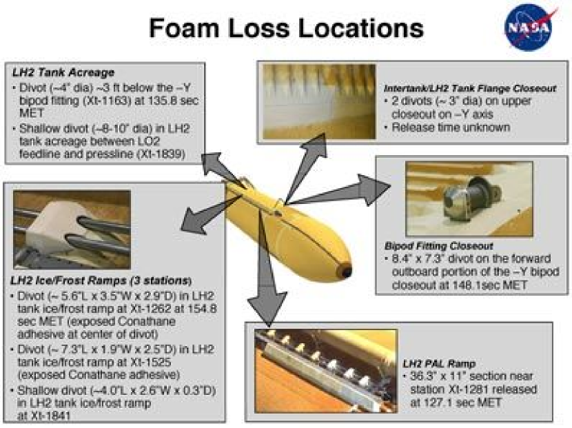
While HST customers were crossing their fingers, the STS-114 camera system exhibited a spectacular scene of a top-hat shape insulation foam flying off the external tank. The public release of the foam loss locations by NASA shown in Fig. 1 read as follows.
-
1.
LH2 PAL ramp: section near stattion Xt-1281 released at 127.1 sec MET;
-
2.
divot on the forward outboard portion of the -Y bipod closeout at 148.1 sec MET;
-
3.
Divot () in LH2 tank ice/frost ramp at Xt-1262 at 154.8 sec MET (exposed Conathane adhesive at center of divot);
-
4.
Divot () in LH2 tank ice/frost ramp at Xt-1525 (exposed Conathane adhesive);
-
5.
Shallow divot () in LH2 tank ice/frost ramp at Xt-1841;
-
6.
Divot ( dia) ft below the -Y bipod fitting (Xt-1163) at 135.8 sec MET;
-
7.
Shallow divot ( dia) in LH2 tank acreage between LO2 feedline and pressline (Xt-1839);
-
8.
2 divots ( dia) on upper intertank/LH2 tank flange closeout on -Y axis (release time unknown).
2 “Rationale” for an Alternative Resolution
The press release by NASA immediately following the dislodge of the large lbs piece of insulation foam from PAL ramp indicates NASA’s continuing efforts to prevent defects in foam bubbles and to tame supersonic vortices and turbulences as it reads in the last paragraph: “… An enhanced spray process is in work for future tanks, as well as continued work in developing redesign options including elimination of the ramps; reducing the ramps’ sizes by two thirds; or building a trailing edge ‘fence’ on the back side of the cable tray, which would act like a nozzle throat and prevent unsteady flow in that area.”
The divots in items 2 and 8 in section 1 are from the left side (-Y) of the bipod area. This is exactly the same area where the lbs piece of foam broke off from the ramp and doomed shuttle Columbia in 2003. The ramps have been removed, and the surface of the foam in the bipod area has been streamlined since. But, the air managed to dump enough energy to break off large chunks from the streamlined foam. The fourth volume of the Columbia Accident Investigation Board (CAIB) Report111 “ET Cryoinsulation” in CAIB Report Volume IV: Appendix F.4, p.16; See also Fig. 3.2.5 in Volume I; http://www.caib.us. exhibits a result of hydrodynamic simulations that shows streamline vortices around the -Y bipod area. We have no clue, especially not being an expert either in supersonic hydrodynamics or in external tank configurations, whether the vortices around the obstacles of the struts that hold the nose of the shuttle can be tamed without undesirable, or unpredictable and untested, side effects. However, NASA’s investments of 2.5 years and billion dollars since Coumbia accident point to a possibility that the same line of efforts cited in the first paragraph of this section might have already served its capacity.
An alternative is suggested to strengthen the insulated external fuel tank with fish-net stockings made of high temperature resistant ceramic fibers that are immediately available. Oxide fiber 3M Nextel 720 manufactured by 3M Technologies is considered.
3 No Foam Loss as Specified in the Book
3.2.1.2.17 External Tank Debris Limits: No debris shall emanate from the critical zone of the External Tank on the launch pad or during ascent except for such material which may result from normal thermal protection system recession due to ascent heating222 “External Tank End Item (CEI) Specification – Part 1,” CPT01M09A, contract NA-58-30300, April 9, 1980, WBS 1.6.2.2..
It is the design requirements in “Flight and Ground System Specification-Book 1, Requirements” as quoted in CAIB report volume 1 chapter 6, p.122. The report continues, “The assumption that only tiny pieces of debris would strike the Orbiter was also built into original design requirements, which specified that the Thermal Protection System (the tiles and RCC panels) would be built to withstand impacts with a kinetic energy less than foot-pounds.”
The corresponding maximum mass and size of the allowed foam bebris is and where the latter is commonly referred to as “the size of a marshmallow” in news media. The large piece foam debris from the PAL ramp on STS-114 is times the maximum allowed. Nextel 720 - fiber properties shown in figures 2, 3, and 4 (electronically cut out of 3MTTN) indicate that the ceramic fiber technology is sufficiently mature to meet the design specification of “no foam loss”.
-
1.
In civilized units (cgs or mks), the impact energy limit foot-pounds is about . Some of the convesion formulae for pressure (or strain) are listed.
(1) (2) -
2.
In order to convert the impact energy limit into the maximum allowed mass of a foam debris, we need to know the areodynamic velocity due to the ascending motion of the spacecraft and wind, air density, streamline, etc, as a function of time and the position in the external tank. A recent review, found in the web site of Lockheed Martin, “STS-114 Flight Readiness Review: External Tank (ET-121),” Appendix D, P.5, June 29-30, 2005, indicates that the mass of a foam debris should not exceed . The density of the foam is , henced the volume of the infimum mass foam debris is . We take and as the currently accepted mass and volume limits.
-
3.
Table 7.2.1.8.1.2.6-1 of CAIB Report titled “Summary of Acreage Stress Analysis Parameters” lists flight requirement (foam) cell pressures in various parts of the foam insulation on the external tank: Oxygen tank: , , depending on the parts; Intertank: ; Hydrogen tank: , and bond tension test requirement: . Hence we take as the tensile strength requirement of the ceramic fiber grid structure.
3.1 High Temperature Resistant Ceramic Fiber 3M Nextel 720
High tensile strength fibers are based in carbon, SiC, and 333 “High Temperature Structural Fibers – Status and Needs”, J.A.DiCarlo, NASA TM-105174, 1991.. Space shuttle RCC panels – now a household name since the Columbia accident – are made of carbon fiber composite matrix with SiC protection coating and glassy sealant444 “Carbon Fiber Composites”, D.D.L.Chung, Butterworth-Heinmann, 1994.,555 “Carbon-carbon composites: engineering materials for hypersonic flight”, NASA TM-103472, 1989.. During the reentry of the shuttle, the sealant melts forming an air tight thin film. A report666 “ Modeling the Thermostructural Capability of Continuous Fiber-Reinforced Ceramic Composites”, J.A.DiCarlo and H.M.Yun, Journal of Engineering for Gas Turbines and Power, 2002, p.467: DY hetherfrom. indicates that oxide fiber tows (or roving: loose bundle of untwisted fibers) perform better than SiC-based tows in the condition under consideration where it is highly oxidating and the usage time is short (). The interactions within the bundle make the tow weaker or stronger in terms of creep or rupture in comparison to the average strength of the single fiber. At , single fiber SiC outperforms SiC tow; At , SiC tow outperforms single fiber SiC. We consider an oxide fiber 3M Nextel 720.
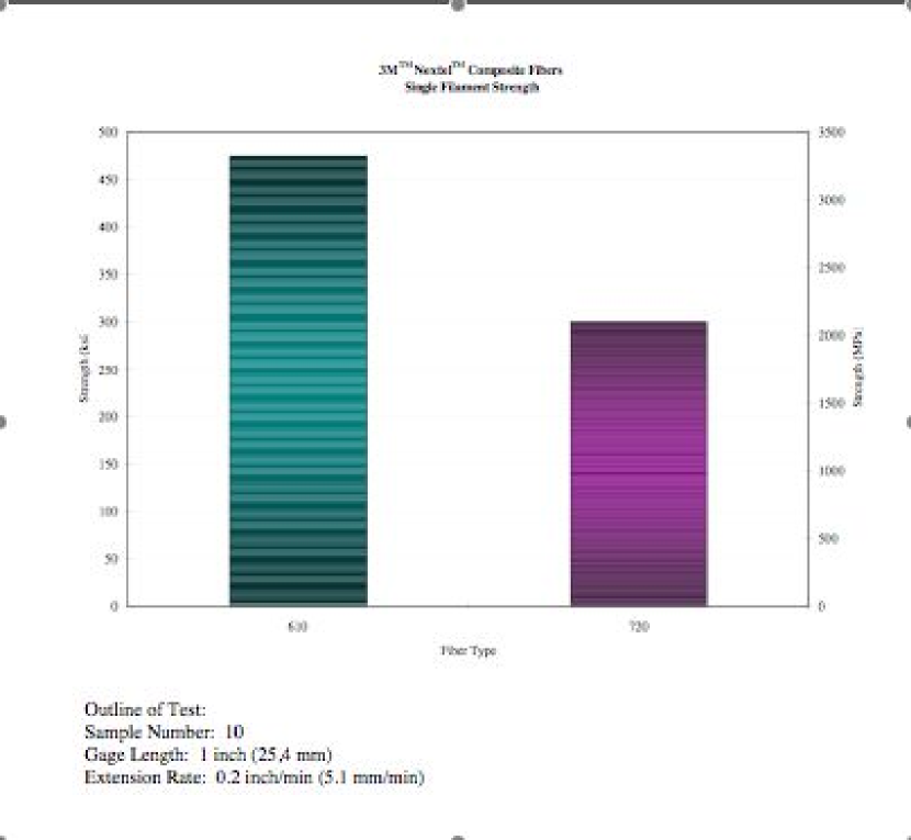
3M Nextel 720 fiber777 “3M Nextel Ceramic Textiles Tecnical Notebook” (http://www.3m.com): 3MTTN from hereon. is a continuous fiber with the composition of 85% and 15% , melting temperature , density , the filament tensile strength at guage, the diamter , and the crystal phase -+mullite. Nextel oxide fibers are various mixtures of , , and . Fiber 610 is made of pure () and its crystal phase is -.
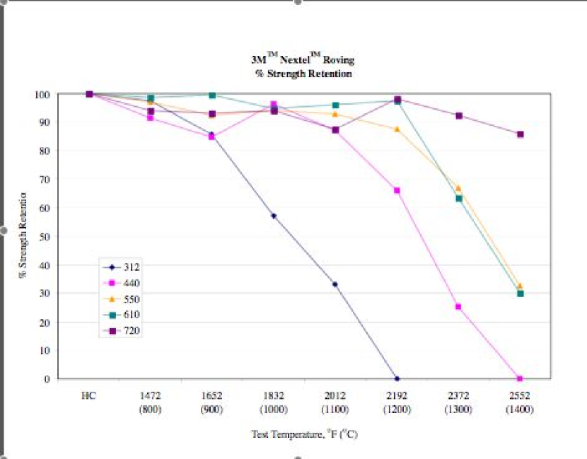
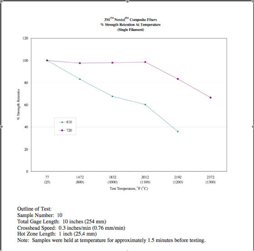
Figure 2 shows the stable strength of fiber 720 tow in high temperatures. (3M Nextel oxide fiber tows come in fiber counts of 400 or 750.) Figures 3 and 4 show the single fiber tensile strengths of the fibers 610 and 720 in room temperature and high temperatures where the high temperature heatings lasted about 90 seconds. (Note that the maximum aerodynamic friction and heating occurs around seconds after the launch.) The fiber 610 is stronger at room temperature, but fiber 720 is preferred because of the stability of the strength in high temperatures. Comparision of figures 2 and 4 shows that the fiber 720 tow performs better than single fiber at higher temperatures () consistently with the report by DY.
The concern of foam shedding is on the area where the aerodynamic stress is high, and the design requirement888 “Return to Flight Focus Area: External Tank Thermal Protection System”, www.nasa.gov. of the temperature tolerance due to aerodynamic heating is . Within the temperature range, fiber 720 shows excellent strength behavior and also very slight difference in the strengths between a tow and an average single fiber. The temperature tolerance requirements for the areas with heating from solid rocket booster and from main engine are very high with and . Foam shedding or ablation from those areas (aft dome and lower part of the acreage) is not a concern in regard to the potential damage to the thermal protection systems (TPS), and reinforcement fibers should not be used to avoid generating unnecessary potential hazard of loose fiber fragments or melts.
3.2 Added Mass Estimation
-
1.
The total acreage of the external tank foam insulation is . (The total mass of the foam is .) The area that needs fiber reinforcement is likely to be less than , and will be considered the fiducial acreage. Most of the foam loss seems to come from intertank area where liquid oxygen tank and liquid hydrogen tank are joined (CAIB report).
-
2.
Consider a single fiber one inch square cell grid. The number of cells in the grid is , the total length of the fiber in the grid is , and the total mass is . (According to 3MTTN, 400 fiber count tow has 1500 denier (denier = number of grams in 9000 m or 10000 yd of a product).) Assuming absolute no failure of the single fiber grid, added weight of of fibers will keep the foams from being released. It is most likely not practicable, but the negligibly small mass of the single fiber grid is a good news. The cost of the single fiber grid will be $66. It is only getting better.
-
3.
The tensile strength measurement is done with a short piece of fiber of length , and I did not find failure probability of long fibers in 3MTTN. The total strength equivalent of 400 or 750 fibers of the commercial products may be more than fail-safe for the lengths of the girth and height of the appication area of the external tank. One can consider woven yarns or very narrow fabric to replace the single fiber strand for the grid. The ceramic fiber net may be embedded near the surface of the foam or wrap the surface. A 1500 fiber-equivalent strength grid will add mass with the price tag of $100,000.
The analysis is preliminary and the mass estimation is made over a broad range because of the lacking information of the properties of long fibers, exact behavior of the insulation foam under stresses, and so the engineering formulation of the grid. For example, the foam will have surface waves generated by the aerodynamic flows, and the fiber (yarn) would need to have certain elasticity whether the fiber grid is embedded or on the surface.999J.D.Walker indicates in “Impact Modeling”, CAIB Report, Volume II, D12 that the foam behaves elastically with strain rates higher than where the estimated Young modulus of the foam is . The proper elasticity may be engineered through the bundle structure such as braiding or weaving. Inelastic fiber can act as a “diamond string saw” to an adverse effect. Even if it shaves off only benignly small pieces, it should be best to avoid generating additional foam flakes.
In summary, a ceramic-fiber-grid reinforcement can eliminate foam-shedding problem. The projected mass and price of the grid are small. There are some details to be specified to engineer a practical ceramic-fiber grid that will secure insulation foam of the external tank – economically. “No foam loss” makes the flight safer and reduces turn-around repair costs. We call for cooperations from the interested parties.
Acknowledgments
We appreciate discussions with J.A.DiCarlo on creep properties of tows and introduction to 3M Technologies and with 3M Technologies personnel on Nextel fibers and the costs, and the library of University of Notre Dame for the access of reference books.