Enhanced Transmission of Light and Matter through Nanoapertures without Assistance of Surface Waves
Abstract
Subwavelength aperture arrays in thin metal films enable enhanced transmission of light and matter waves [for example, see T.W. Ebbesen et al., Nature (London) 391, 667 (1998) and E. Moreno et al., Phys. Rev. Lett. 95, 170406 (2005)]. The phenomenon relies on resonant excitation of the surface electron or matter waves. We show another mechanism that provides a great transmission enhancement not by coupling to the surface waves but by the interference of diffracted evanescent waves in the far-field zone. Verification of the mechanism is presented by comparison with recently published data.
pacs:
42.25.Bs, 42.25.Fx, 42.79.Ag, 42.79.DjThe scattering of waves by apertures is one of the basic phenomena in the wave physics. The most remarkable feature of the light scattering by subwavelength apertures in a metal screen is enhancement of the light by excitation of electron waves in the metal. Since the observation of enhanced transmission of light through a 2D array of subwavelength metal nanoholes Ebb , the phenomenon attracts increasing interest of researchers because of its potential for applications in nanooptics and nanophotonics Barn . Recently, the enhanced transmission through subwavelength apertures was predicted also for matter waves More . The enhancement of light is a process that can include resonant excitation and interference of surface plasmons More ; Schr ; Sobn ; Port , Fabry-Perot-like intraslit modes Asti ; Taka ; Lala ; Barb , and evanescent electromagnetic waves at the metal surface Leze . In the case of thin screens whose thickness are too small to support the intraslit resonance, the extraordinary transmission is caused by the excitation of surface plasmons or their matter-wave analog, surface matter waves More ; Schr ; Sobn ; Port . In this Letter, we show another mechanism that provides a great transmission enhancement not by coupling to the surface electron or matter waves but by the interference of diffracted evanescent waves in the far-field zone.
The transmission enhancement without assistant of surface waves can be explained in terms of the following theoretical formulation. We first consider the transmission of light through a structure that is similar but simpler than an array of holes, namely an array of parallel subwavelength slits. The structure consists of a thin metal screen with the slits separated by many wavelength. To exclude the plasmons from our model, the metal is considered to be a perfect conductor. Such a metal is described by the classic Drude model for which the plasmon frequency tends towards infinity. Owing to the great distance between the slits, the electromagnetic field at one slit is assumed to be independent from other slits. The transmission of the slit array is determined by calculating the light power in the far-field diffraction zone. The waves diffracted by each of the independent slits are found by using the Neerhoff and Mur approach, which uses a Green’s function formalism for a rigorous numerical solution of Maxwell’s equations for a single, isolated slit Neer ; Harr ; Betz . The calculations show a big, up to 5 times, resonant transmission enhancement near to the Fabry-Perot wavelengths determined by an array period. To clarify the numerical result, we then present an intuitively transparent analytical model, which quantitatively explains the resonant enhancement in terms of the far-field-zone interference of the evanescent waves produced by the independent slits. The model predicts the 5-times (resonant) and 1000-times (nonresonant) enhancements for both the light and matter waves passing through a perforated metallic or dielectric screen, independently on the apertures shape. Verification of the analytical formulae by comparison with data published in the literature supports these predictions. The Wood anomalies in transmission spectra of optical gratings, a long standing problem in optics Hess , follow naturally from interference properties of the model.
Let us first investigate the light transmission by using the rigorous model. The model considers an array of independent slits of width and period in a screen of thickness . The screen placed in vacuum is illuminated by a normally incident TM-polarized wave with wavelength . The magnetic field of the wave is assumed to be time harmonic and constant in the direction. The transmission of the slit array is determined by calculating all the light power radiated into the far-field diffraction zone, at the distance from the screen. The total per-slit transmission coefficient, which represents the per-slit enhancement in transmission achieved by taking a single, isolated slit and placing it in an -slit array, is then found by using an equation , where is the power radiated by a single slit. Figure 1 shows the transmission coefficient , in the spectral region 500-2000 nm, calculated for the array parameters: nm, nm, and .
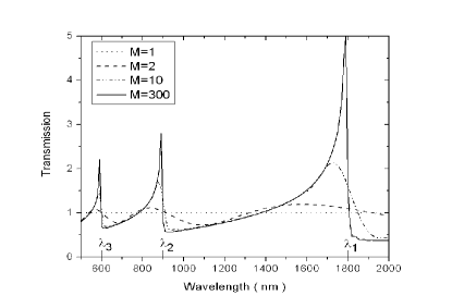
The transmitted power was computed by integrating the total energy flux at the distance = 1 mm over the detector region of width = 20 mm. The transmission spectra is shown for different values of . We notice that the spectra is periodically modulated, as a function of wavelength, below and above a level defined by the transmission of one isolated slit. As is increased from 2 to 10, the visibility of the modulation fringes increases approximately from 0.2 to 0.7. The transmission exhibits the Fabry-Perot like maxima around wavelengths . The spectral peaks increase with increasing the number of slits and reach a saturation () in amplitude by , at nm. The peak widths and the spectral shifts of the resonances from the Fabry-Perot wavelengths decrease with increasing the number of slits. From the data of Fig. 1, one can understand that enhancement and suppression in the transmission spectra are the natural properties of an ensemble of independent subwavelength slits in a thin () screen. The spectral peaks are characterized by asymmetric Fano-like profiles. Such modulations in the transmission spectra are known as Wood’s anomalies. The minima and maxima correspond to Rayleigh anomalies and Fano resonances, respectively Hess . The weak Wood’s anomalies are present also in the case of , a classical Young type two-slit system.
The above-presented data is based on calculation of the energy flux by using the electromagnetic field evaluated numerically. The transmission enhancement is achieved by taking a single, isolated slit and placing it in an array. The interference of the waves diffracted by the independent slits can be considered as a physical mechanism responsible for the enhancement. To clarify the numerical results and gain physical insight into the enhancement mechanism, we have developed an analytical model, which yields simple formulae for the diffracted fields. For the fields diffracted by a narrow () slit into the region , it can be shown that the Neerhoff and Mur model simplifies to an analytical one. For the magnetic and electric fields we found:
| (1) |
| (2) |
and
| (3) |
where
| (4) |
and
| (5) |
Here, , , and are the Hankel and Struve functions, respectively. The fields are spatially nonuniform, in contrast to a common opinion that a subwavelength aperture diffracts light in all directions uniformly Lez . The fields produced by an array of independent slits are given by and , where and are the fields of an -th beam generated by the respective slit. As an example, Fig. 2(a) compares the far-field distributions calculated by the analytical formulae (1-5) to that obtained by the rigorous model. We notice that the distributions are undistinguishable.
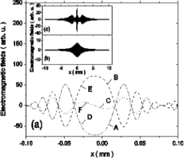
Thus, the analytical model not only supports results of our rigorous model, but presents an intuitively transparent explanation of the enhancement in terms of the interference of the fields produced by the multi-beam source. The array-induced decrease of the central beam divergence (Figs. 2(b) and 2(c)) is relevant to the beaming light Mart , and the nondiffractive light and matter waves Kuk .
The analytical model accurately describes the fields and , but what is about the transmission coefficient? The field power , which determines the coefficient , is found by integrating the energy flux . Thus, the model accurately predicts also the light transmission. We now consider the predictions in light of the key observations published in the literature for the two fundamental systems of wave optics, the single-slit and two-slit systems. The major features of a single-slit system are the intraslit resonances and the spectral shifts of the resonances from the Fabry-Perot wavelengths Taka . In agreement with the predictions Taka , the formula (4) shows that the transmission = = ReIm exhibits Fabry-Perot like maxima around wavelengths , where is the power impinging on the slit opening. The enhancement and spectral shifts are explained by the wavelength dependent terms in the denominator of Eq. (4). The enhancement ( Kuk ) is in contrast to the attenuation predicted by the model Taka . The Young type two-slit configuration is characterized by a sinusoidal modulation of the transmission spectra Scho ; Lalan . The modulation period is inversely proportional to the slit separation . The visibility of the fringes is of order 0.2, independently of the slit separation. In our model, the transmission is given by , where and . The high-frequency modulations with the sideband-frequency (Figs. 1 and 3) are produced as in a classic heterodyne system by mixing two waves having different spatial frequencies, and .
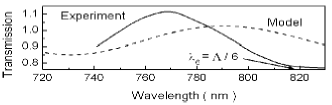
Although our model ignores the plasmons, its prediction for the visibility ( 0.1) of the fringes and the resonant wavelengths compare well with the plasmon-assisted Young’s type experiment Scho (Fig. 3). Some difference between the calculated and measured values shows that the plasmonless and plasmon-assisted resonances can compete in certain situations. In the case of , the resonances at can be accompanied by the intraslit resonances at .
In order to gain physical insight into the mechanism of plasmonless enhancement in a multi-slit () system, we now consider the dependence of the transmission on the slit separation . We assume that the slits are independent also at .
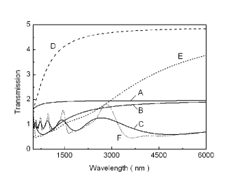
According to the Van Citter-Zernike coherence theorem, a light source (even incoherent) of radius produces a transversally coherent wave at the distance in the region of radius . Thus, in the case of , the collective emission of the ensemble of slits generates the coherent electric and magnetic fields, expexp and exp. Consequently, the maximum power of the emitted light scales with the square of the number of slits (beams), . Therefore, the transmission () grows linearly with the number of slits, . For a given , the function monotonically varies with . Such an enhancement regime (first regime) is shown in Fig. 4. At appropriate conditions, the transmission can reach 1000-times enhancement (). The transmission enhancement in the second regime does not require close proximity of the slits. In the case of (), the beams arrive at the detector with different phases . Consequently, the power and transmission grow slowly with the number of slits (Figs. 1-4). According to our model, the transmission exhibits the Fabry-Perot like maxima around wavelengths . The constructive and destructive interference of the beams leads respectively to the enhancement and suppression of the transmission amplitudes as in a classical heterodyne system.
The analytical model gives not only intuitively transparent explanation of the plasmonless transmission enhancement, but in contrast to the previous studies, predicts the enhancement for the matter waves. Indeed, in our model, the enhancement is based on coherent excitation of an assemble of slits and constructive interference of the diffracted waves. The constructive interference is provided not by coupling between the slits, but by a geometrically well-defined phase relationship between wave amplitudes at different lateral locations in the far-field zone. Thus, the enhancement mechanism depends neither on the nature (light or matter) of the fields nor on material and shape of the apertures. For instance, in the first enhancement regime, the fixed phase correlation leads to the -times enhancement of the field amplitude, , and consequently to the -time transmission enhancement. Due to Babinet’s principle, the model predicts the enhancement also in the reflection spectra. The destructive interference of the fields at the detector can lead also to the zero transmission. Indeed, the interference of the positive () and negative () fields produces a field with the zero amplitude and energy. The value =0 is obtained by summing up the respective positive and negative energies. Notice that the amplitudes of the fields can rapidly decrease with increasing the distances , and . However, due to the enhancement and beaming mechanisms (Figs. 1-4), an array produces a nonevanescent (propagating) wave with low angle divergence. Such a behavior is in agreement with the Huygens-Fresnel principle, which considers a propagating wave as a superposition of secondary spherical waves.
It is worth noting that the presented model is similar in spirit to the dynamical Bloch-waves diffraction model Trea , the Airy-like model based on the Rayleigh field expansion Cao , and especially to a diffracted evanescent wave model Leze . The difference arises from a fact that the models Leze ; Trea ; Cao consider the case of , while predictions of our model strongly depend on the number of slits. In addition, our model deals with independent slits, while the models of Refs. Leze ; Trea ; Cao consider the slits electromagnetically coupled via the periodic boundary conditions. There is an evident resemblance also between our model and a Dicke superradiance model Dick of collective emission of an ensemble of atoms. A quantum reformulation of our model can help us to understand why a quantum entangled state of photons is preserved on passage through a hole array Alte . The quantum model will be presented in our next paper. Notice, that the surface waves can couple the radiation phases of the different slits, so that they get synchronized, and a collective emission can release the stored energy as an enhanced radiation. This kind of enhancement is of different nature compared to our model. The model does not require coupling between the slits and does not contain surface waves.
In conclusion, a rigorous model based on a Green’s function formalism and an analytical model were proposed for description of the transmission of light through an array of independent slits. Using the analytical model we showed a physical mechanism that provides a big transmission enhancement of light or matter waves not by coupling to the surface waves but by the interference of diffracted evanescent waves in the far-field zone. The verification of the analytical formulae by comparison with data published in the literature supports the predictions. The Wood anomalies in transmission spectra of optical gratings, a long standing problem in optics, follows naturally from interference properties of the model. The analytical formulae can be useful for experimentalists who develop nanodevices based on transmission and beaming of light or matter by subwavelengths apertures.
This study was supported by the Hungarian Scientific Research Foundation (OTKA, Contract No T046811).
References
- (1) T.W. Ebbesen et al., Nature (London) 391, 667 (1998).
- (2) W.L. Barnes et al., Nature (London) 424, 824 (2003).
- (3) E. Moreno et al., Phys. Rev. Let. 95, 170406 (2005).
- (4) U. Schröter and D. Heitmann, Phys. Rev. B 58, 15419 (1998).
- (5) M.B. Sobnack, et al., Phys. Rev. Lett. 80, 5667 (1998).
- (6) J.A. Porto, F.J. Garcia-Vidal, and J.B. Pendry, Phys. Rev. Lett. 83, 2845 (1999).
- (7) S. Astilean, P. Lalanne, and M. Palamaru, Opt. Comm. 175, 265 (2000).
- (8) Y. Takakura, Phys. Rev. Lett. 86, 5601 (2001).
- (9) P. Lalanne et al., Phys. Rev. B 68, 125404 (2003).
- (10) A. Barbara et al., Eur. Phys. J. D 23, 143 (2003).
- (11) H.J. Lezec and T. Thio, Opt. Exp. 12, 3629 (2004).
- (12) F. L. Neerhoff and G. Mur, Appl. Sci. Res. 28, 73 (1973).
- (13) R.F. Harrington and D.T. Auckland, IEEE Trans. Antennas Propag. AP28, 616 (1980).
- (14) E. Betzig, A. Harootunian, A. Lewis, and M. Isaacson, Appl. Opt. 25, 1890 (1986).
- (15) A. Hessel and A.A. Oliner, Appl. Opt. 4, 1275 (1965).
- (16) H.J. Lezec et al., Science 297, 820 (2002).
- (17) L. Martin-Moreno, F.J. Garcia-Vidal, H.J. Lezec, A. Degiron, T.W. Ebbesen, Phys. Rev. Lett. 90, 167401 (2003).
- (18) S.V. Kukhlevsky et al., J. Mod. Opt. 50, 2043 (2003), Opt. Commun. 231, 35 (2004), Phys. Rev. B 70, 195428 (2004).
- (19) H.F. Schouten, et al., Phys. Rev. Lett. 94, 053901 (2005).
- (20) P. Lalanne, et al., Phys. Rev. Lett. 95, 263902 (2005).
- (21) M.M.J. Treacy, Phys. Rev. B 66, 195105 (2002).
- (22) Q. Cao and P. Lalanne, Phys. Rev. Lett. 88, 057403 (2002).
- (23) R.H. Dicke, Phys. Rev. Lett. 93, 439 (1954).
- (24) E. Altewischer, et al., Nature (London) 418, 304 (2002).