Preprint of:
Wolfgang Singer, Timo A. Nieminen, Ursula J. Gibson,
Norman R. Heckenberg and Halina Rubinsztein-Dunlop
“Orientation of optically trapped nonspherical birefringent particles”
Physical Review E 73(2), 021911 (2006)
Orientation of optically trapped nonspherical birefringent particles
Abstract
While the alignment and rotation of microparticles in optical traps has received increased attention recently, one of the earliest examples has been almost totally neglected—the alignment of particles relative to the beam axis, as opposed to about the beam axis. However, since the alignment torques determine how particles align in a trap, they are directly relevant to practical applications. Lysozyme crystals are an ideal model system to study factors determining the orientation of nonspherical birefringent particles in a trap. Both their size and their aspect ratio can be controlled by the growth parameters, and their regular shape makes computational modelling feasible. We show that both external (shape) and internal (birefringence) anisotropy contribute to the alignment torque. Three-dimensionally trapped elongated objects either align with their long axis parallel or perpendicular to the beam axis depending on their size. The shape-dependent torque can exceed the torque due to birefringence, and can align negative uniaxial particles with their optic axis parallel to the electric field, allowing application of optical torque about the beam axis.
pacs:
87.80.Cc,42.62.Be,42.25.BsI Introduction
Optical tweezers have been used to manipulate and investigate microscopic particles for many years, and a wide variety of applications have been explored. The underlying principle behind optical tweezers is the transfer of momentum from the trapping beam to the particle Ashkin et al. (1986). As light can carry angular momentum as well as linear momentum, torque can also be exerted on particles in optical tweezers.
The optical torque acting about the beam axis is always a result of the alteration of orbital and/or spin angular momentum of the incident beam by the trapped particle, by absorption or by scattering if there is either external (shape) or internal (birefringence) anisotropy Nieminen et al. (2004a). Consequently, the torque can either originate from a beam where the incident light itself carries angular momentum that is transferred to the particle, or it can originate from a beam where the incident light carries zero angular momentum, but where the trapped particle induces angular momentum in the beam.
A variety of methods to accomplish angular momentum transfer have been proposed and tested Friese et al. (1996); Galajda and Ormos (2001); Bishop et al. (2003). Of these, one of the best suited for actual practical applications is the transfer of incident spin angular momentum to birefringent particles Friese et al. (1998); Bishop et al. (2004); La Porta and D.Wang (2004). Firstly, spin angular momentum can easily be measured, so that the applied optical torque can be determined by purely optical means, making the system well suited for quantitative measurements Nieminen et al. (2001a); Bishop et al. (2004). Secondly, the torque can be controlled by changing the polarization state of the light, keeping the power constant. Thirdly, the torque is quite high, typically on the order of per photon per second if highly birefringent particles are used. Finally, this method can be used with Gaussian beams, ensuring high 3D trapping efficiency.
However, in order to act as a wave plate, the birefringent particle cannot be oriented with the optic axis parallel to the beam axis. Only for other orientations is the polarization state of the light altered and spin angular momentum transferred from the beam to the particle, causing either constant particle rotation in circularly polarized light or particle alignment in linearly polarized light. Obviously, maintaining the required orientation is crucial for the use of birefringent particles as micromotors or for other applications requiring rotation.
Similar principles apply to flattened or elongated particles which also can alter the angular momentum of the incident light only if their asymmetry about the beam axis is conserved after being trapped. Orientation effects due to the shape of the particle have been reported previously. In particular, it has long been known that elongated particles tend to align with their long axis along the axis of the trapping beam Ashkin et al. (1987). However, this behaviour is not universal, and the orientation of trapped particles depends on their size, shape, and optical properties Nieminen et al. (2001b).
The torques giving rise to the orientation of particles with respect to the beam axis have received little attention; this is due in part to the transient nature of the torques, which act to align the particle when it is trapped, and also to the difficulty of calculating torques on nonspherical particles. Earlier work has usually made use of the geometric optics approximation Gauthier (1997), or been restricted to particles of simple geometry and homogeneous and isotropic material Bayoudh et al. (2003). Extension of these foundations to smaller particles for which geometric optics fails, and to more complex particles is highly desirable.
Here we will present numerical calculations—substantiated by experimental results—on how birefringent particles with different aspect ratios and radii will align after being three-dimensionally trapped. Moreover, we are completing the picture of shape-dependent alignment of particles, showing that elongated particles can align with their long axis either parallel or perpendicular to the beam axis, depending on their aspect ratio and size compared to the beam waist.
However, the internal anisotropy (birefringence) also contributes to the torque that determines orientation relative to the beam axis. This torque—like the one due to the shape—only occurs at the beginning of a trapping event and has also not yet been studied in detail. Our results reveal that the birefringence-induced torque responsible for alignment to the beam axis has the same order of magnitude as the birefringence-induced torque about the beam axis. This is in contrast to the shape-induced torque which can be an order of magnitude larger relative to the beam axis as compared to the one about the beam axis Bayoudh et al. (2003).
We show both experimentally and by computational modelling that, depending on the respective anisotropy, one aligning effect can dominate the other. Using growing lysozyme crystals we were able to observe the transition where the alignment torque due to birefringence overcomes the torque due to shape when we changed the aspect ratio of a particle while trapped. These findings explain how negative uniaxial calcite crystals can be spun in circularly polarized light Friese et al. (1998), despite the fact that such crystals tend to align with their optic axis parallel to the beam axis La Porta and D.Wang (2004).
II Orientation of lysozyme crystals
Lysozyme crystals are a widely used model to study nucleation and growth of protein crystals. In its most common (tetragonal) form, lysozyme forms a positive uniaxial birefringent crystal, with a well-characterized morphology. A schematic drawing showing the crystallographic axes and faces can be found in reference Singer et al. (2005). The optic axis, which coincides with the crystal’s c-axis, points from one tip to the other tip of the crystal. The difference in the indices along the [001] and [110] axes at 1064 nm is Singer et al. (2004). The relative ordinary refractive index () was found to be from the measured trap stiffness Nieminen and Knöner (2005). The aspect ratio is defined as the length along the optic axis to the width of the [110] face.
The size and shape distributions of lysozyme crystals can be controlled by varying the initial salt and protein concentrations. This allows the experimental study of the shape-dependence of the orientation of optically trapped particles. The size and aspect ratio can even be changed dynamically, while the lysozyme crystal is held in the optical trap.
The experiments were carried out using a setup described in detail by Singer et al. Singer et al. (2004). Briefly, linearly polarized light from an Yb-doped fiber laser operating at 1070 nm in the range of 200–500 mW was coupled into a oil-immersion objective of numerical aperture 1.4, with a resulting beam waist radius of m. A half-wave plate in the beam path could be used to adjust the direction of the plane of polarization of the trapping beam. The exact alignment of the individual particles in the trap could be determined using a software package developed by Gibson and Kou Gibson and Kou (2005).
We calculated the optical force and torque acting on lysozyme crystals in an optical trap by using the T-matrix method to determine the scattering of the trapping beam by the crystal, and finding the difference between the inflow and outflow of electromagnetic momentum and angular momentum, which is equal to the force and torque exerted on the crystal Nieminen et al. (2004b, 2003a, 2003b); Bishop et al. (2003).
Since calculation of the T-matrix is much faster for axisymmetric particles Waterman (1971), the lysozyme crystals were modelled as cone-tipped cylinders. Since their relative refractive index is close to 1, and their birefringence is small, even compared with this small refractive index contrast, it was possible to assume an effective isotropic refractive index (which is a function of the orientation of the crystal) to separately calculate the torque due to the shape. The torque due to the birefringence was then calculated using the angle-dependence of the orientation energy of the birefringent material in the applied field; this procedure, while approximate, is valid in the low-contrast low-birefringence case of lysozyme crystals.
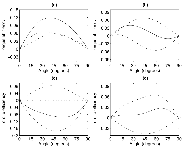
Equilibrium orientations were found from the dependence of torque on the angle between the axis of the crystal model and the beam axis. The torque versus angle for different aspect ratios is shown in figure 1. Three distinct regimes of behaviour—alignment with the crystal optic axis perpendicular to the beam axis, parallel to the beam axis, and at an intermediate angle—can be identified. This behaviour can be understood in terms of the usual behaviour of nonspherical particles in optical traps—such particles tend to align with their longest dimension along the beam axis. Therefore, a high-aspect ratio lysozyme crystal (elongated along the optic axis) will align with the optic axis parallel to the beam axis. For crystals with smaller aspect ratios the body diagonal is the longest axis and alignment with the body diagonal parallel to the beam axis is to be expected, leading to the optic axis being skewed to the beam axis by an angle depending on the aspect ratio Singer et al. (2005). This type of alignment is widely observed with flattened particles Bayoudh et al. (2003). Meanwhile, since the crystals are positive uniaxial, the torque due to birefringence acts to align the optic axis perpendicular to the beam axis. For low aspect ratio (flattened) particles, both the torque due to shape and the torque due to birefringence act in the same direction, and the crystal aligns with the optic axis perpendicular to the beam axis, as seen in figure 1(a). For elongated crystals, these torques oppose each other, and the transition to alignment along the beam axis requires a larger aspect ratio than would be the case without birefringence.
However, this simple picture fails to explain the existence of the third regime—alignment with the optic axis perpendicular to the beam axis. Notably, the shape torque alone would result in alignment at an intermediate angle, at an angle of . Since the birefringence torque acts to align the optic axis perpendicular to the beam axis, but is insufficient to completely overcome the torque due to shape, this angle is increased to .
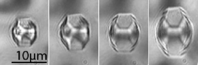


We observed all three types of alignment with lysozyme crystals of varying size and aspect ratio. Since it is possible to grow crystals while they are trapped, we were able to observe the transitions between these regimes of alignment in individual crystals. Figure 2 shows the growth of a trapped crystal while the protein concentration in the solution was changed, with a change in orientation between frames 2 and 3. It can be seen that for the given growing conditions the crystal is growing primarily by addition of material on the (110) faces, as would be expected at a high protein concentration Forsythe et al. (1999). The measured angle between the optic axis of the crystal and the beam axis is shown in figure 3. The transition to the perpendicular alignment occurs when the torque due to the birefringence of the crystal becomes dominant over the shape-dependent torque. However, even if the crystals were optically isotropic, this transition would still occur (though at a smaller aspect ratio) when the shape-dependent torque changes direction.
The observed equilibrium orientations of a number of lysozyme crystals of varying size and aspect ratio are shown in figure 4. The calculated extents of the different regimes of orientation are also shown, and agree well with the observed orientations. The crystals were all in the same sample. Note that the crystals drawn in figure 4 to show the equilibrium orientation in each regime are shown in side view, while figure 2 shows their appearance when viewed in the microscope (ie a top view).
III Other particles
While the previous results apply specifically to lysozyme crystals, which have a low refractive index contrast with the medium and a small birefringence, the same general principles apply to other particles as well. While the shape-dependent torque varies with the refractive index of the particle (proportional to the refractive index contrast in the low-contrast limit), the orientations for which the torque is zero only weakly depends on the refractive index—a refractive index contrast ten times larger yields boundaries between the regimes of orientation very similar to those in figure 4.
This is especially relevant when we consider the trapping and rotation about the beam axis of birefringent particles. If the particle is positive uniaxial, the birefringence-dependent torque acts to align the optic axis perpendicular to the beam axis. The torque on a negative uniaxial particle, on the other hand, acts to align the optic axis with the beam axis. If this is the equilibrium orientation of the particle, the particle appears to be isotropic as far as the incident beam is concerned, and no transfer of angular momentum occurs La Porta and D.Wang (2004); Nieminen et al. (2004a). This raises the question of why optically trapped negative uniaxial crystals have been observed to spin Friese et al. (1998). It appears reasonable to suppose that, especially since the crystals in question were irregular, shape-dependent torques produced an equilibrium orientation such that the optic axis was not parallel to the beam axis.
It can also be seen in figure 4 that, if the particle is small compared to the beam waist, elongated particles can align with their long axis perpendicular to the beam axis, in agreement with previous results for very small particles Nieminen et al. (2001b). These findings can be explained by the fact that particles that are small compared to the beam waist are trapped in the centre of the focal spot, where the intensity gradient is small. The elongated objects therefore align with the axis of the highest particle polarisability—their longest axis—in the direction of the electric field vector, and therefore perpendicular to the beam axis, rather than parallel to the beam axis.
IV Conclusions
Of the several methods to orient and rotate microscopic particles in optical tweezers, by the far the most important to date, as far as quantitative measurements are concerned, is transfer of spin angular momentum to birefringent particles Nieminen et al. (2001a); Bishop et al. (2004); La Porta and D.Wang (2004). However, the ability to use birefringent particles is restricted to those which orient with their optic axis not parallel to the beam axis after being trapped, which at first appears to rule out the use of negative uniaxial materials. We have shown that the torque due to nonspherical shape can overcome the torque due to birefringence, and can be used to maintain negative uniaxial particles in the desired orientation. Furthermore, we showed that elongated particles small compared to the beam waist will align perpendicular to the beam axis.
The results presented are relevant to the design of particles that can be used as motors in optically-driven micromachines, and have potential to increase the range of particles that can serve to probe properties of microscopic or biological systems. The predictability and computability of these torques enables their practical use in optical micromanipulation.
V Acknowledgements
We would like to acknowledge the support of NASA grant NAG8-1590, the University of Queensland and the Australian Research Council. We are indebted to Gregor Knöner and Simon Parkin for their contributions.
References
- Ashkin et al. (1986) A. Ashkin, J. M. Dziedzic, J. E. Bjorkholm, and S. Chu, Opt. Lett. 11, 288 (1986).
- Nieminen et al. (2004a) T. A. Nieminen, S. J. Parkin, N. R. Heckenberg, and H. Rubinsztein-Dunlop, Proc. SPIE 5514, 254 (2004a).
- Friese et al. (1996) M. E. J. Friese, J. Enger, H. Rubinsztein-Dunlop, and N. R. Heckenberg, Physical Review A 54, 1593 (1996).
- Galajda and Ormos (2001) P. Galajda and P. Ormos, Applied Physics Letters 78, 249 (2001).
- Bishop et al. (2003) A. I. Bishop, T. A. Nieminen, N. R. Heckenberg, and H. Rubinsztein-Dunlop, Phys. Rev. A 68, 033802 (2003).
- Friese et al. (1998) M. E. J. Friese, T. A. Nieminen, N. R. Heckenberg, and H. Rubinsztein-Dunlop, Nature 394, 348 (1998), erratum in Nature, 395, 621 (1998).
- Bishop et al. (2004) A. I. Bishop, T. A. Nieminen, N. R. Heckenberg, and H. Rubinsztein-Dunlop, Phys. Rev. Lett. 92, 198104 (2004).
- La Porta and D.Wang (2004) A. La Porta and M. D.Wang, Phys. Rev. Lett. 92, 190801 (2004).
- Nieminen et al. (2001a) T. A. Nieminen, N. R. Heckenberg, and H. Rubinsztein-Dunlop, Journal of Modern Optics 48, 405 (2001a).
- Ashkin et al. (1987) A. Ashkin, J. M. Dziedzic, and T. Yamane, Nature 330, 769 (1987).
- Nieminen et al. (2001b) T. A. Nieminen, H. Rubinsztein-Dunlop, and N. R. Heckenberg, in CLEO®/Pacific Rim 2001 Technical Digest (IEEE, Piscataway, NJ, USA, 2001b), vol. 2, pp. 138–139.
- Gauthier (1997) R. C. Gauthier, Journal of the Optical Society of America B 14, 3323 (1997).
- Bayoudh et al. (2003) S. Bayoudh, T. A. Nieminen, N. R. Heckenberg, and H. Rubinsztein-Dunlop, Journal of Modern Optics 50, 1581 (2003).
- Singer et al. (2005) W. Singer, T. A. Nieminen, U. Gibson, N. Heckenberg, and H. Rubinsztein-Dunlop, Proceedings of SPIE 5736, 16 (2005).
- Singer et al. (2004) W. Singer, H. Rubinsztein-Dunlop, and U. Gibson, Opt. Express 12, 6440 (2004).
- Nieminen and Knöner (2005) T. A. Nieminen and G. Knöner, Measurement of refractive index of small particles using optical tweezers (2005), unpublished.
- Gibson and Kou (2005) U. J. Gibson and Y. Kou, Appl. Crystall. 38, 559 (2005).
- Nieminen et al. (2004b) T. A. Nieminen, N. R. Heckenberg, and H. Rubinsztein-Dunlop, Proc. SPIE 5514, 514 (2004b).
- Nieminen et al. (2003a) T. A. Nieminen, H. Rubinsztein-Dunlop, and N. R. Heckenberg, J. Quant. Spectrosc. Radiat. Transfer 79-80, 1005 (2003a).
- Nieminen et al. (2003b) T. A. Nieminen, H. Rubinsztein-Dunlop, and N. R. Heckenberg, J. Quant. Spectrosc. Radiat. Transfer 79-80, 1019 (2003b).
- Waterman (1971) P. C. Waterman, Physical Review D 3, 825 (1971).
- Forsythe et al. (1999) E. L. Forsythe, A. Nadarajah, and M. L. Pusey, Acta Crystallographica D 55, 1005 (1999).