An Instructional Scaffolding for Intuitive Explanation of “Why does not a spinning top collapse?”
Abstract
“Why does not a spinning top collapse?” is a puzzling question. Standard solution using angular momentum and torque is not intuitive enough. Thus intuitive explanations for the question have been proposed. We provide scaffolding for an intuitive explanation for the question. Accelerated point-masses in the top exert forces on the frame, which balances the effect due to gravity. The explanation is supplemented by the two following points. A more rigorous conceptual framework of the explanation is provided. A full calculation of trajectory is given. Nutation of spinning top is a difficult issue to understand physically. However, the nutation can also be understood by the intuitive explanation. We discuss another intuitive explanation. PACS: 45.40.Cc
I Introduction
“Why does not a spinning top collapse?” is a question that has puzzled many physicists. A standard solution can be found in textbooks, e.g. Refs. Hal93 ; Fey63 ; Tho95 : Torque on a top is given such that angular momentum of the top makes a closed loop around the vertical axis. The solution is simple and rigorous. However, the solution is not intuitive enough. This situation is not so satisfactory. Students beginning to study physics often experience difficulties in understanding true meaning of explanations.
Intuitive explanations were given by Barker Bar60 , Eastman Eas75 , and Edwards Edw77 . Explanation by Eastman and Edwards is interesting but somewhat confusing. Explanation by Barker got to the heart of the problem; Accelerated point-masses in the top exert forces on frame to generate torque which balances torque due to gravity. However, there are two points to be supplemented; Conceptual framework of the explanation is not presented in detail. Although idea for the calculation is provided with correct results, full trajectory is not given. These points will make the explanation more difficult to be understood. The purpose of this paper is to supplement the explanation in the points. Our presentation may work as a scaffolding for the explanation by Barker.
A rotating object is simpler than the spinning top. But both objects have the same nature with respect to its explanations. Thus we adopt the rotating object as preparation step in section II-A. In section II-B, we give the explanation for the spinning top. Core of the explanation can be found in Fig. 2 with its caption. Section II-C deal with nutation of spinning top. Eastman’s explanation is discussed in Section III. Then we summarize in the last section.
II Scaffoldings for Intuitive Explanation
II.1 Step 1: A rotating object
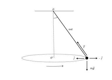
Let us consider a model, an object composed of a point-mass with mass and a rod in Fig.1. We assume that the mass-point rotates with a fixed angular speed making a circle drawn with dotted line. For simplicity of discussion, we assume that the rod has negligible mass. The rod has a joint a origin . That is, its upper end is fixed at but it can freely rotate. We assume that the hinge can give no torque on the rod. Here the origin with which the torque is defined is . Thus force by the rod, denoted by , should be along the rod, like in the case of a string.
Now let us consider the same question that arises for the rotating object: Why does not the object move downward by gravity? This question can be answered in two standard ways.
Explanation of type 1 for rotating object: Newton’s laws explain the motion: Force on the point-mass, , namely sum of gravity and tension , accelerates the point-mass inwardly such that it makes a circular motion Hal93 .
Explanation of type 2 for rotating object: We adopt a non-inertial frame co-moving with the point-mass. Fictitious force in the non-inertial frame is centrifugal force denoted by . The balances two other forces, that is, . Hence the point-mass has zero acceleration in the non-inertial frame.
Let us give other explanations. Here we adopt an inertial frame, and we focus on “the rod” not on the object composed of the rod and the point-mass. Then we show that torque exerted on the rod is zero 111Exactly speaking, mass of the rod is non-zero. Thus torque on the rod in vertical direction should be non-zero. In this case, however, analysis is complicated. For simplicity, we assume that rod has zero mass.. If the torque is not zero, the rod will turn making the point-mass move upward or downward. Now let us estimate torque on the rod. In order to do that, we need to know forces which act on the rod. There are two forces on the rod. One is force by hinge. However, the force by hinge gives zero torque because it acts on the origin . The other is force by the point-mass. Our task is to estimate force.
Proposition-1: Here is force that is required to maintain the (rotational) motion of the point-mass. Let force on the rod by the point-mass denoted by . Then we have .
Let us see why Proposition-1 holds. Let us assume in Fig.1 that the gravity is removed while the motion of object is maintained somehow. Force that should be given on the point-mass to maintain the constant rotation is and the only thing that can exert force on the point-mass is the rod. Thus it should be that the rod is giving a force to the point-mass. By the third law of Newton, the force on the rod by the point-mass is . Intuitive interpretation of the force will be given later. Now let us assume that the gravity is restored. There can be no change in the force on the point-mass since the motion of point-mass is the same. However, the force is differently composed. In case of zero gravity, the force on the point-mass is solely provided by the that of the rod. In case of non-zero gravity, the force on the point-mass is sum of that by the rod and gravity on the point-mass, . Therefore, the force by the rod must be . However, due to the third law of Newton, the force by the point-mass on the rod is an opposite of the force. That is, force on the rod by the point-mass is .
It is notable that the Proposition-1 applies to not only the motion in Fig. 1 but to motion of spinning top in Fig. 2.
Using Proposition-1, we get,
Explanation of type 3 for rotating object: The force on the rod by the point-mass, , gives zero torque on the rod. Thus the rod will not make turning motion that makes the point-mass move vertically.
Let us see what will happen if only the force were exerted on the rod. In this case, the rod gets a torque that turns the rod so that the point-mass moves upward. In this sense, the rotation of point-mass gives a “floating force”. Similarly, if only gravity were exerted, the rod get an opposite torque that turns the rod so that the point-mass moves downward. We get an explanation of Barker type Bar60 .
Explanation of type 4 for rotating object: The gravity gives a torque to turn the rod such that the point-mass moves downward. However, the force gives a torque to turn the rod oppositely such that the point-mass moves upward. The two torques are balanced and thus the mass-point does not move vertically.
II.2 Step 2: A spinning top
Our arguments here are mostly in parallel with those in the previous subsection. The difference is that we deal with a spinning top as in Fig. 2: The top is a simplified one composed of four point-masses with mass and a massless frame. Initially, when , four point-masses are in the plane, the top spins about axis with angular speed , and the top precesses about axis with angular speed . The frame is composed of a stem with length and four branches with length . Initial speed of the point-mass is given by .
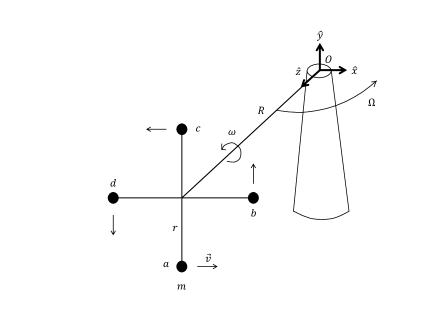
Now let us calculate torque on the frame with respect to origin . We will apply the Proposition-1. What we need is the force . Force on the point-mass by the frame can be calculated from trajectory that the point-mass makes.
Let us calculate trajectory of each point-mass in order to get acceleration of it. Let us set up coordinate systems as in Fig. 3, where unit vectors and are instantaneous rectangular coordinate systems co-moving with the stem.
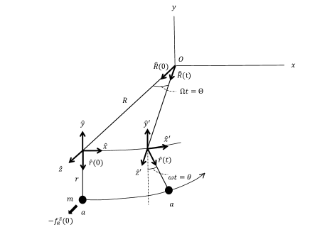
The relationship between the two coordinate systems is given by
| (1) |
as we see.
Using the coordinate system we calculate trajectory of each point-mass. First, we calculate trajectory of point-mass , . The trajectory is sum of a location vector and another location vector ,
| (2) |
where and are unit vectors as shown in Fig. 3. We can see that
| (3) |
and that
| (4) | |||||
where Eq. (1) is used. By combining Eqs. (2)-(4), we obtain
| (5) | |||||
From Eq. (5), we obtain
| (6) | |||||
What we consider is the situation when . From Eq. (6), we get
| (7) |
Thus the force on the point-mass when is
| (8) | |||||
Let us give an interpretation of Eq. (8). The first term, , is due to the rotation involved with angular speed . However, the second term, , is due to combination of both rotations, the one involved with angular speed and the other one involved with angular speed . The force along direction is non-zero, which can also be seen from trajectory shown in Fig. 3: The trajectory is curved toward origin as well as toward direction.
Similarly, we can calculate net forces on other point-masses when :
| (9) | |||||
| (10) | |||||
and
| (11) | |||||
Note that and are similar to and , respectively. Reaction on branch by each point-mass is where . By Proposition-1, force on the frame by each point-mass, is given by
| (12) |
Now we are prepared to calculate torque at , due to force . First let us separately calculate sum of torques due to term of four point-masses,
| (13) |
where is the unit vector in -direction. Let us calculate remaining torque due to term : By inspecting spatial arrangement of vectors in Eqs. (9)and (11), we can see that and involved with point-masses and cancel each other, . However, by inspecting spatial arrangement of vectors in Eqs. (8) and (10), we can see that sum of torques involved with point-masses and is non-zero, that is, . Therefore,
| (14) |
By Eqs. (13) and (14), we get total torque,
| (15) |
However, if a condition,
| (16) |
is satisfied, the total torque is zero. This means that frame does not make turning motion which will make the point-masses vertically. Interestingly, this is the condition for the precession of the top found in text books Hal93 .
Explanation of type 3 for spinning top: The total torque on the frame is zero. Thus the frame does not make turning motion that will make the point-masses move vertically. Namely the frame doesn’t fall.
However, the other end of frame is fixed at the origin and the frame is a solid body. Thus, if the torque and were separately exerted on the frame, the frame would turn such that the point-masses move downward and upward, respectively. Now we can give a Barker-type explanation.
Explanation of type 4 for spinning top: The downward force on the frame due to the torque by gravity, , is balanced by the floating (upward) force due to the torque by point-masses, . Thus spinning top does not collapse.
II.3 Other motions of a top
As discussed in Ref. Bar60 , it is interesting to see that the explanations can be applied to other motions of the top, the nutation Fey63 . Contrary to our simple-minded notion, even a spinning top does fall depending on situation. Let us consider a motion described in Ref. Fey63 . “If we were to hold the axis absolutely fixed, so that it cannot process in any manner (but the top is spinning) then there is no torque acting, not even a torque from gravity, because it is balanced by our fingers. But if we suddenly let go, then there will instantaneously be a torque from gravity. Anyone in his right mind would think that top would fall, and that is what it starts to do, as can be seen if the top is not spinning too fast. The gyro actually does fall, as we would expect. …” How can we explain the “falling of spinning top with (temporarily) fixed axis”? We can find an explanation of the Explanation of type 3.
Explanation of type 3 for the case when top falls: Because the spinning axis is (temporarily) fixed, as we can see, there is no floating force obtained by precession of the axis. Therefore, the top falls down due to downward force by gravity.
However, the falling of spinning top with (temporarily) fixed axis does not last so long. The top would begin to move horizontally such that the top makes a cycloid, as described in Fig. 20-5 of Ref. Fey63 . We can also give an explanation for this motion.
Explanation of type 3 for horizontal acceleration of top: The falling makes the top “precess” toward direction temporarily. However, as we have seen in section II, a precession toward direction induces a force toward direction on the frame. By the same mechanism, the precession toward direction induce a force toward direction on the frame. Therefore, the falling top accelerates in direction also.
Now we can understand why the top makes a cycloid at least qualitatively.
III Discussion about Eastman’s explanation
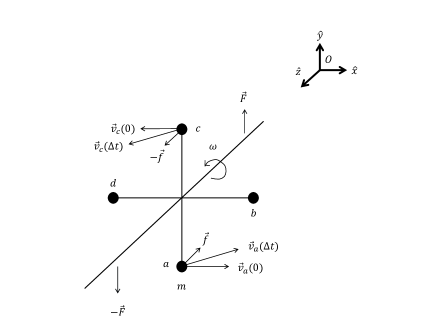
Assume that impulses, and , are applied during a time duration , to a spinning top. These impulses induces forces along the axis, and , on the point-masses and along and direction, respectively. The forces, and , then change velocities and of point-masses and to and , respectively. Here and . Here is mass of each point-mass. As a result, the spinning axis of the top is rotated by an angle that and make. The axis of the top precesses in a direction that is perpendicular to the impulses.
Eastman’s explanation has an advantage of being simple. However,it also has difficulties. First, it is not clear how the impulses, and , induces forces, and . What the authors of had in mind seems to be the following. The impulses make point-masses and move slightly along direction. Then the motion induces the forces and . In contrast, the impulses do not make point-masses and move and thus no forces are induced on the point-masses and . However, it is not clear how the motions can induce the forces and in the same direction.
Second, actual trajectories of point-masses are not taken into account in the Eastman’s model. The Eastman’s model cannot explain the fact that the same spinning top either does or does not fall down depending on initial condition. According to the Eastman’s model the direction of precession is unchanged as long as the direction of impulses are the same. However, the impulses provided by the gravity is unchanged. This implies that the spinning top would not fall down, which contradicts facts.
IV Conclusion
Barker’s explanation about why spinning top does not collapse got to the heart of the problem: Reaction of top’s point-masses exert torque on top’s frame, that balances torque due to gravity. Here we supplemented the explanation. More rigorous conceptual-framework and calculations for the explanation are given. Our presentation may work as a scaffolding for the explanation. Another motion of top, the nutation, can also be understood in terms of the intuitive explanation. We discussed another intuitive explanation.
Acknowledgements.
I am grateful to Profs. Intaek LIM and Jongwon PARK for helpful discussions. This study was supported by Basic Science Research Program through the National Research Foundation of Korea (NRF) funded by the Ministry of Education, Science and Technology (2010-0007208).References
- (1) Email address: wyhwang@jnu.ac.kr
- (2) D. Halliday, R. Resnick, J. Walker, Fundamentals of Physics, 4th ed., (John Wiley and Sons, Inc., New York, 1993), Chap. 12.
- (3) R. Feynman, M. Sands, and R. Leighton, The Feynman Lectures on Physics, (Addison Wesley Longman, 1963), Chap. 20.
- (4) S. T. Thornton, Classical Dynamics of Particles and Systems, 4th ed., (Harcourt Brace and Company, Florida, 1995), Chap. 11.
- (5) E. M. Barker, Am. J. Phys. 28, 808 (1960).
- (6) P. C. Eastman, Am. J. Phys. 43, 365 (1975).
- (7) P. L. Edwards, Am. J. Phys. 45, 1194 (1977).