Fully Coherent X-ray Pulses from a Regenerative Amplifier Free Electron Laser
Abstract
We propose and analyze a novel regenerative amplifier free electron laser (FEL) to produce fully coherent x-ray pulses. The method makes use of narrow-bandwidth Bragg crystals to form an x-ray feedback loop around a relatively short undulator. Self-amplified spontaneous emission (SASE) from the leading electron bunch in a bunch train is spectrally filtered by the Bragg reflectors and is brought back to the beginning of the undulator to interact repeatedly with subsequent bunches in the bunch train. The FEL interaction with these short bunches not only amplifies the radiation intensity but also broadens its spectrum, allowing for effective transmission of the x-rays outside the crystal bandwidth. The spectral brightness of these x-ray pulses is about two to three orders of magnitude higher than that from a single-pass SASE FEL.
pacs:
41.50.+h, 41.60.Crpacs:
41.50.+h,41.60.CrAn x-ray free electron laser (FEL) based on self-amplified spontaneous emission (SASE) is an important first step towards a hard x-ray laser and is expected to revolutionize the ultrafast x-ray science (see, e.g., Refs. LCL (2002); TES (2002)). Despite its full transverse coherence, a SASE x-ray FEL starts up from electron shot noise and is a chaotic light temporally. Two schemes have been proposed to improve the temporal coherence of a SASE FEL in a single pass configuration. A high-gain harmonic generation (HGHG) FEL uses available seed lasers at ultraviolet wavelengths and reaches for shorter wavelengths through cascaded harmonic generation Yu and Wu (2002). In this process, the ratio of electron shot noise to the laser signal is amplified by at least the square of the harmonic order and may limit its final wavelength reach to the soft x-ray region Saldin et al. (2002). Another approach uses a two-stage SASE FEL and a monochromator between the stages Feldhaus et al. (1997). The SASE FEL from the first undulator is spectrally filtered by a monochromator and is then amplified to saturation in the second undulator. This approach requires an undulator system almost twice as long as a single-stage SASE FEL.
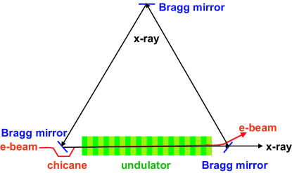
Another seeding scheme, a regenerative amplifier FEL (RAFEL), has been demonstrated in the infrared wavelength region Nguyen et al. (1997) and discussed in the ultraviolet wavelength region Faatz et al. (1999). It consists of a small optical feedback and a high-gain FEL undulator. In the hard x-ray region, perfect crystals may be used in the Bragg reflection geometry for x-ray feedback Colella and Luccio (1984); Adams and Materlik (1996) and have been demonstrated experimentally for x-ray photon storage (see, e.g., Ref. Liss et al. (2000); shvydko (1999)). In this paper, we propose and analyze a novel x-ray RAFEL using narrow-bandwidth, high-reflectivity Bragg mirrors. The basic schematic is shown in Fig. 1. Three Bragg crystals are used to form a ring x-ray cavity around a relatively short undulator. Alternative backscattering geometry with a pair of crystals may also be used. SASE radiation from the leading electron bunch in a bunch train is spectrally filtered by the Bragg reflectors and is brought back to the beginning of the undulator to interact with the second bunch. This process continues bunch to bunch, yielding an exponentially growing laser field in the x-ray cavity. The FEL interaction with these short bunches not only amplifies the radiation intensity but also broadens its spectrum. The downstream crystal transmits the part of the radiation spectrum outside its bandwidth and feeds back the filtered radiation to continue the amplification process. Compared to a SASE x-ray FEL that typically requires more than 100 m of undulator distance, this approach uses a significantly shorter undulator but a small number of electron bunches to generate multi-GW x-ray pulses with excellent temporal coherence. The resulting spectral brightness of these x-ray pulses can be another two to three orders of magnitude higher than the SASE FEL.
We first consider a one-dimensional (1-D) model of the narrow-bandwidth RAFEL to describe its main characteristics such as the temporal profile, the round-trip power gain and the maximum extraction efficiency. At the beginning of the undulator pass, the radiation field is represented by , where is the arrival time relative to the longitudinal center of the electron bunch. The radiation field at the exit of the undulator is
| (1) |
where is the SASE signal of the electron bunch. When the radiation slippage length is much smaller than the electron bunch length, we can assume the electric field gain factor is a function of the local beam current which can be approximated by
| (2) |
where is the rms pulse duration of a Gaussian bunch current. The more precise gain dependence on the current is used in numerical simulations shown below.
The amplified signal is then spectrally filtered by the Bragg mirrors and is fed back to the entrance of the undulator in the pass, i.e.,
| (3) |
where is a Gaussian spectral filter function with the rms intensity bandwidth , and is the central frequency of the filter with the power reflectivity . For a high-gain amplifier after a few passes, the seed signal dominates over the SASE, so that we can neglect the second term on the right side of Eq. (1). Integrating Eq. (3) over the frequency yields
| (4) |
Since there is no initial seed signal, , and
| (5) |
is the spectrally filtered SASE from the first pass that seeds the second pass.
For , we look for an exponentially growing solution
| (6) |
Eq. (4) is then transformed to an integral equation:
| (7) |
with the kernel
| (8) |
Since both and may be complex, is in general not a hermitian kernel.
We expect that a Gaussian fundamental mode will have the largest gain , i.e.,
| (9) |
Here is the rms pulse duration of the returning filtered radiation. Inserting Eq. (9) into Eq. (7), we obtain
| (10) |
where is the rms x-ray pulse duration at the undulator end (see Eq. (14)). The self-consistent solution of Eq. (10) is
| (11) | |||
Thus, the round-trip power gain is
| (12) |
where is the peak FEL gain, and is the peak reflectivity of the feedback system. Regenerative amplification requires that . Note that depends on the time-bandwidth product , but not on or separately.
The filtered radiation power at the undulator entrance for is then
| (13) |
where is the effective noise power within the narrow bandwidth that starts the process. The amplified radiation at the end of the undulator pass is
| (14) |
with given by Eq. (11). If we neglect any absorption in the crystal, the part of the radiation energy (with frequency content mainly outside the feedback bandwidth) may be transmitted with the maximum efficiency
| (15) |
In view of Eq. (12), the maximum extraction efficiency is also a function of the time-bandwidth product .
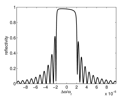
As a numerical example, we discuss how the proposed RAFEL might be implemented in the Linac Coherent Light Source (LCLS) LCL (2002). The x-ray wavelength is chosen to be about 1.55 Å since diamond (400) crystals may be used at a Bragg angle . The diamond (115) reflection plane may be as well chosen at 1.2 Å for the same Bragg angle. Three such crystals are necessary to form an x-ray cavity as shown in Fig. 1. The reflectivity curve of a 100-m-thick diamond (400) crystal for the 8-keV, -polarized radiation is shown in Fig. 2 as computed by XOP del Rio and Dejus . The x-ray reflectivity within the Darwin width rad, corresponding to the flattop region of Fig. 2 with . The expected rms angular divergence of the FEL radiation is about 0.5 rad, which is well within the Darwin width but washes out the interference fringes shown in Fig. 2. The crystals may be bent slightly to provide the necessary focusing of the filtered radiation at the undulator entrance.
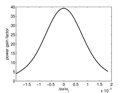
In order to accelerate a long bunch train in the SLAC linac, we use the entire rf macropulse available without the rf pulse compression (SLED). The maximum LCLS linac energy, without the SLED, is about 10 GeV. Table 1 lists the beam and undulator parameters that are typical for x-ray FELs such as the LCLS, except that the length of the undulator is only 20 m instead of more than 100 m planned for the LCLS. We perform the three-dimensional (3-D) GENESIS Reiche (1999) FEL simulation that shows the maximum power gain after the 20-m undulator, with the fwhm relative gain bandwidth about (see Fig. 3). The LCLS accelerator and bunch compressor systems are expected to generate a bunch current profile which is more flattop than Gaussian, with a flattop duration fs LCL (2002). If we take and in Eq. (12), we obtain the round-trip gain under these parameters.
| Parameter | Symbol | Value |
|---|---|---|
| electron energy | 9.9 GeV | |
| number of bunches | 10 to 11 | |
| bunch spacing | s | |
| bunch charge | pC | |
| bunch peak current | 3 kA | |
| fwhm bunch duration (flattop) | 100 fs | |
| rms energy spread at undulator | ||
| transverse norm. emittance | 1 m | |
| undulator mean beta function | 18 m | |
| undulator period | 0.03 m | |
| undulator parameter | 2.4 | |
| FEL wavelength | 1.55 Å | |
| photon energy | 8 keV | |
| FEL parameter | ||
| undulator length | m | |
| maximum FEL gain per pass | ||
| 3-crystal bandwidth | ||
| 3-crystal reflectivity |
We have developed a 1-D FEL code that simulates the regenerative amplification process. The electron rms energy spread is increased in the 1-D code to so that the 1-D FEL gain matches the 3-D FEL gain determined by parameters in Table 1. The simulation using a flattop current profile and a nearly flattop crystal reflectivity curve shows that the round-trip gain in the exponential growth stage and that the RAFEL reaches saturation within 10 x-ray passes. For a total x-ray cavity length of 75 m (25 m for each of three cavity arms in Fig. 1), the duration of the 10-bunch train is about 2.25 s, well within the 3.5-s uncompressed rf pulse length even after taking into account the structure filling time ( s). The beam loading is estimated to be small for less than 2 mA average current within the bunch train. To stay within the FEL gain bandwidth as shown in Fig. 3, the relative energy variation within the bunch train should be less than 0.05%. A bunch-to-bunch time jitter of about 100 fs would require a 11-bunch train of 2.5 s in order for the FEL to reach saturation.
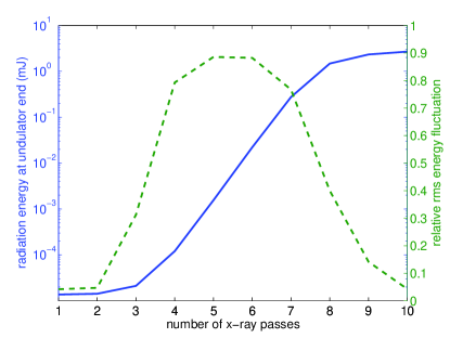
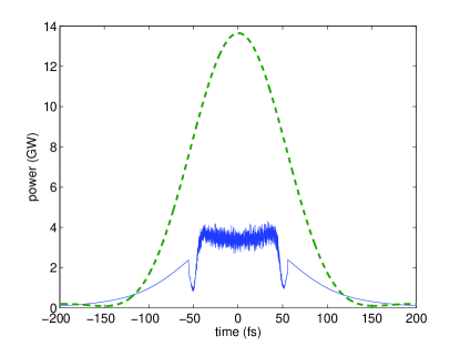
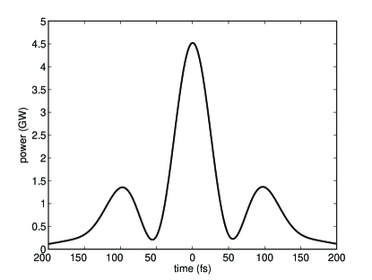
Figure 4 shows that the radiation energy at the undulator end is mainly the broadband SASE radiation in the first three passes or so and is then dominated by the narrow bandwidth filtered signal up to the FEL saturation. Figures 5 shows the temporal profile of the reflected and transmitted FEL power for a 100-m-thick diamond crystal with about 82% transmission outside the crystal bandwidth around 8 keV. The broadband SASE radiation transmitted through the end crystal (the noisy part of the blue solid curve in Fig. 5) can be separated from the narrow-bandwidth signal by another monochromator following the transmission as demonstrated in Fig 6. The total x-ray energy dose absorbed by the undulator-end crystal (FEL plus spontaneous radiation) is estimated to be two orders of magnitude smaller than the melting dose level for diamond. Finally, Fig. 4 also shows that the shot-to-shot radiation energy fluctuates up 90% in the exponential growth stage but quickly reduces to about 5% at the end of the 10th pass. Although a monochromator may also be used in a saturated SASE FEL to select a single longitudinal mode, the radiation power will be reduced by the ratio of the SASE bandwidth to the monochromator bandwidth, and the filtered radiation energy still fluctuates 100%.
While we consider a ring x-ray cavity with Bragg reflection for illustration, the RAFEL scheme and its analysis presented in the paper is equally applicable to a backscattered x-ray cavity with Bragg reflection. The round-trip time of such a cavity is only two thirds of the ring cavity shown in Fig. 1, allowing for 50% more electron bunches in a bunch train of the same duration to participate in the RAFEL process. The reflectivity at exactly Bragg reflection for cubic crystals such as diamond may be complicated by multiple-wave diffraction and has not been studied here. Crystals with lower structure symmetry such as sapphire may provide the necessary high reflectivity in backscattering as demonstrated in Ref. shvydko (1999).
In summary, we have described a narrow-bandwidth regenerative amplifier FEL (RAFEL) at the hard x-ray wavelength region using Bragg crystals that produces nearly transform limited x-ray pulses in both transverse and longitudinal dimensions. Compared to a SASE x-ray source that possesses a typical bandwidth on the order of , the bandwidth of an x-ray RAFEL can be more than two orders of magnitude smaller, resulting in a factor of a few hundred improvement in spectral brightness of the radiation source. The use of multiple bunches in a bunch train for regenerative amplification allows for a relatively short undulator system and may be adapted in the LCLS using the SLAC s-band linac. Since superconducting rf structures can support a much longer bunch train in an rf macropulse, an x-ray RAFEL based on a superconducting linac may require a much lower single pass gain and hence relax some of beam and jitter requirements provided that the additional radiation damage to the x-ray optics is tolerable. Therefore, the method described in this paper is a promising approach to achieve a fully coherent x-ray laser.
We thank J. Hastings and J. Arthur for useful discussions on x-ray optics. Z. H. thanks K.-J. Kim for general discussions and for providing Refs. Colella and Luccio (1984); Adams and Materlik (1996). This work was supported by Department of Energy contracts DE–AC02–76SF00515.
References
- LCL (2002) LCLS Conceptual Design Report, SLAC-R-593, (2002).
- TES (2002) TESLA XFEL Technical Design Report (Supplement), TESLA-FEL-2002-09 (2002).
- Yu and Wu (2002) L.-H. Yu, Phys. Rev. A 44, 5178 (1991).
- Saldin et al. (2002) E. Saldin, E. Schneidmiller, and M. Yurkov, Opt. Commun. 202, 169 (2002).
- Feldhaus et al. (1997) J. Feldhaus et al., Opt. Commun. 140, 341 (1997).
- Nguyen et al. (1997) D. Nguyen et al., Nucl. Instrum. Methods A 429, 125 (1999).
- Faatz et al. (1999) B. Faatz et al., Nucl. Instrum. Methods A 429, 424 (1999).
- Colella and Luccio (1984) R. Colella and A. Luccio, Opt. Commun. 50, 41 (1984).
- Adams and Materlik (1996) B. Adams and G. Materlik, in Proceedings of the 1996 Free Electron Lasers, II–24, (Elsevier, Amsterdam, 1997).
- Liss et al. (2000) K.-D. Liss et al., Nature 404, 371 (2000).
- shvydko (1999) Yu. Shvyd’ko et al., Phys. Rev. Lett. 90, 013904 (2003).
- (12) M. S. del Rio and R. Dejus, “XOP - X-ray oriented programs”, http://www.esrf.fr/computing/scientific/xop/.
- Reiche (1999) S. Reiche, Nucl. Instrum. Methods A 429, 243 (1999).