Self-optimization of optical confinement in ultraviolet photonic crystal slab laser
Abstract
We studied numerically and experimentally the effects of structural disorder on the performance of ultraviolet photonic crystal slab lasers. Optical gain selectively amplifies the high-quality modes of the passive system. For these modes, the in-plane and out-of-plane leakage rates may be automatically balanced in the presence of disorder. The spontaneous optimization of in-plane and out-of-plane confinement of light in a photonic crystal slab may lead to a reduction of the lasing threshold.
pacs:
42.55.Tv,42.25.Dd,42.55.PxOver the past few years, tremendous progress has been made in design and fabrication of photonic crystal slab (PhCS) lasers that operate in infra-red (IR) spectrum range mode_delocalization ; Painter_noda_park ; noda_science ; Akahane:2003 ; akahane_nat_mat ; scherer2 ; bandedge_exp . To realize an ultraviolet (UV) PhCS laser, the feature size has to be reduced roughly by a factor of four our_apl ; our_pbg_calc compared to IR PhCS. Fabrication of such fine structures inevitably generates random deviations from the perfectly ordered structures. In passive PhC devices such uncontrollable disorder has detrimental effect as it contributes to optical losses and limits light propagation length. However, it is not clear how the disorder would affect the performance of an active device, e.g., a PhCS laser. In this letter we illustrate, through numerical simulation and experiment, that structural disorder in a PhC laser may not be as detrimental as in a PhC waveguide. Under some circumstances structural disorder enables self-optimization of optical confinement in a PhCS, leading to a reduction of lasing threshold.
A PhCS utilizes index guiding to confine light to the plane of the slab phcs_confinement . In-plane confinement is realized either via a defect state located inside a photonic bandgap (PBG) Painter_noda_park ; Akahane:2003 ; akahane_nat_mat ; scherer2 , or a bandedge state with vanishing group velocity polymer_phcs ; gain_at_be ; noda_science ; bandedge_exp . Light may escape from the PhCS vertically through the top/bottom interfaces into air/substrate or laterally via the edge of the periodic pattern into air or unpatterned part of the slab. The vertical leakage rate is characterized by the out-of-plane energy loss per optical cycle , and the lateral by . A defect state spatially localized in the vicinity of an intentionally-introduced structural defect typically has large leakage in the vertical direction, i.e., . For a bandedge state, the lateral leakage usually dominates over the vertical one, . The total loss is described by . Low lasing threshold demands maximization of , which is hindered by for a defect state and for a bandedge state. Several designs aim at optimization of PhCS lasers by balancing and via “gentle localization” Akahane:2003 , e.g., phase-slipphase_slip ; scherer2 , double-heterostructure akahane_nat_mat .
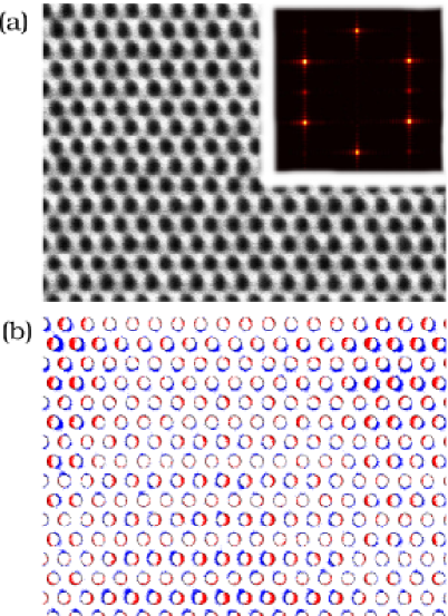
Recently we realized the first UV PhCS laser our_apl . ZnO films were grown on sapphire substrates by plasma enhanced MOCVD xiang_liu . Hexagonal arrays of cylindrical air voids were patterned in the ZnO films by focused ion beam (FIB) etching technique. The lattice constant nm, the radius of air cylinders nm. Post thermal annealing was employed to remove the FIB damage. Single-mode lasing at room temperature was realized with optical pumping. The scanning electron micrograph (SEM) of a ZnO PhCS is shown in Fig. 1(a). Despite the long-range periodicity exhibited in the inset of Fig. 1(a), Fig. 1(b) reveals the deviation of the fabricated pattern from the ideal honeycomb structure. Such “crescent” deviation vos_disorder caused optical scattering on the length scale of a few lattice constants. It was expected to enhance radiative leakage of a PhCS laser based on either defect state or bandedge mode. Moreover, the propagation loss in a passive PhCS caused by randomdisorder_latest scattering was predicted to increase dramatically near a photonic bandedge disorder_at_be , where the bandedge-type PhCS laser operates. Despite of these pessimistic expectations based on passive systems, we show that the performance of a PhCS laser may be less susceptible to the detrimental effects of structural disorder. This is because optical gain predominantly amplifies the mode with the highest quality factor . For the highest- mode, the vertical and lateral leakage rates may be automatically balanced in the presence of disorder. This implies that an appropriate amount of structural disorder could lead to spontaneous optimization of in-plane and out-of-plane confinement of light in a PhCS.
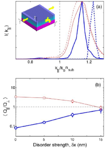
To investigate how the disorder affects the rates of vertical and lateral leakages of light from a PhCS, we consider a system schematically depicted in the inset of Fig. 2(a). A dielectric slab of thickness 180 nm and refractive index is sandwiched between air and substrate (). Within the slab, infinitely-long grooves run parallel to -axis. The width of a groove is 22 nm, the lattice constant of the disorderless structure is 100 nm. We consider light propagating in - plane, with the electric field along -axis. Such system is 2D, that allows numerical simulation of large statistical ensembles of random systems. Despite the simplification, the system in Fig. 2(a) retains the property essential for our study of PhCS laser: the possibility of vertical (along -axis) and lateral (along -axis) radiative escape. Using the finite-difference time-domain (FDTD) method, we find the mode of the passive system that has the highest disphc . A Gaussian pulse was launched at all spatial points in the slab and the energy is allowed to leak out radiatively. Simulation area is terminated by uniaxially perfectly matched absorbing layer that absorbs all outgoing waves. The pulse excites all modes within nm wavelength range around nm. After the initial multi-mode decay the field distribution is stabilized and the longest-lived mode can be seen. This is further confirmed by observing a mono-exponential decay of the total energy disphc ; mode_delocalization stored in the system that allows determination of . By integrating Poynting vector over the corresponding interfacesmode_delocalization , we obtained the outgoing flux in the vertical and horizontal directions, and and . In our simulation, relation was satisfied numerically to within .
Fourier transform of the spatial profile of electric field at the interface between the slab and substrate gives the mode’s distribution in (in-plane component of the wavevector) space. In a perfectly periodic structure, the bandedge mode has the highest-. It is spatially extended in , thus has a narrow distribution in [thick dashed curve in Fig. 2(a)]. Next we intentionally create a defect by increasing the spacing between two neighboring grooves at the center of the pattern to 150 nm. The highest- mode is localized around this artificial defect with a localization length of 140 nm. Strong localization in results in a broad distribution in [thin dashed curve in Fig. 2(a)], with the maximum lying closer to the edge of substrate light-cone [dash-dotted vertical line in Fig. 2(a)]. Its is limited by , which is about three times smaller than the corresponding in a system of . In contrast, the bandedge mode is concentrated well beyond the light-cone in -space, thus its is much higher. However, its spatial extension makes the lateral leakage larger, hence its is limited by .
To simulate the position disorder of air cylinders in real structure [Fig. 1(b)], random variation of groove position is introduced. We choose randomly from a uniform distribution with the standard deviation 5, 10, 15 nm. characterizes the “strength” of disorder. As the disorder is introduced, the highest- state differs from realization to realization, and the correspondent , as well as the frequency vary. We study statistical distributions of these parameters and their dependences on disorder strength and system size .
In small systems ( = 12 and 24) with an artificial defect and weak disorder ( nm), the highest- modes always concentrate around the defect at the center of the pattern. These modes become more spatially extended than those without disorder. Therefore, their -distribution is narrowed and component within the light-cone is significantly reduced [Fig. 2(a)]. This reduction leads to a decrease in the vertical leakage, thus, an increase in . Meanwhile, starts increasing as the mode gets less localized in real space. The ensemble-averaged , shown in Fig. 2(b), decreases monotonously to unity with increase of disorder strength. Therefore, disorder removes the imbalance between vertical and lateral leakages of a single defect state, making . As a result, the ensemble-averaged quality factor is slightly higher than that without disorder. In a larger system or with stronger disorder, the highest- mode is no longer pinned at the artificial defect. Instead, it can explore the entire pattern to find the optimum configuration for the best vertical and lateral confinement. This leads to a further increase of .
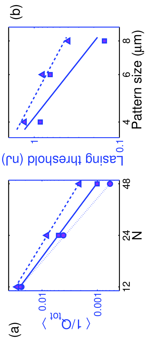
With the introduction of disorder, bandedge mode becomes less extended. As its “tail” moves away from the boundaries of the pattern, the lateral leakage decreases, thus increases. Meanwhile, the distribution in -space is broadened and shifted closer to the light-cone edge [Fig. 2(a)]. The increase in vertical leakage results in a decrease of . The ensemble-averaged , shown in Fig. 2(b), rises continuously to unity with increasing disorder strength. Again, disorder balances the vertical and lateral leakages of the bandedge mode, as it does to the defect state. However, for a bandedge mode the increase in is not as large as the decrease in , thus is slighter lower than that without disorder. Nevertheless, as the pattern size increases, the total leakage rate decreases monotonically: [Fig. 3(a)]. The exponent decreases from 2.3 at nm to 1.9 at nm. Even with the largest disorder we simulated ( nm), no saturation of with is observed up to . This behavior differs fundamentally from that of a photonic crystal waveguide, where optical loss increases exponentially with its length. In contrast, a disordered PhCS laser benefits from an increase of the pattern size, simply because a larger system provides a bigger pool of modes from which the highest- mode can be selected. This effect should be more pronounced in PhCS microlasers with 2D periodicity [Fig. 1(a)], due to the larger phase-space compared to the numerically simulated systems with 1D periodicity.
Experimentally, we fabricated ZnO PhCS of dimensions m, m, and m [Fig. 1(a)]. Since the complete photonic bandgap in ZnO PhCS without “undercut” was quite narrow our_pbg_calc , it was technically challenging to overlap PBG with ZnO gain spectrum. By adjusting the magnification of focused ion beam system, we were able to change the lattice constant in fine steps of 3 nm over a wide range nm. The ratio of the air hole radius to the lattice constant was also varied from to . In this way, we could tune PBG continuously through ZnO gain spectrum. We also introduced an artificial defect by missing an air hole. Structural analysis as in Fig. 1(b) gives the average displacement of a hole .
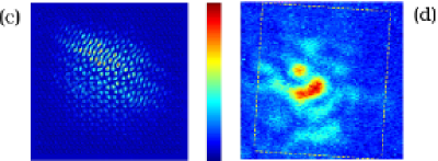
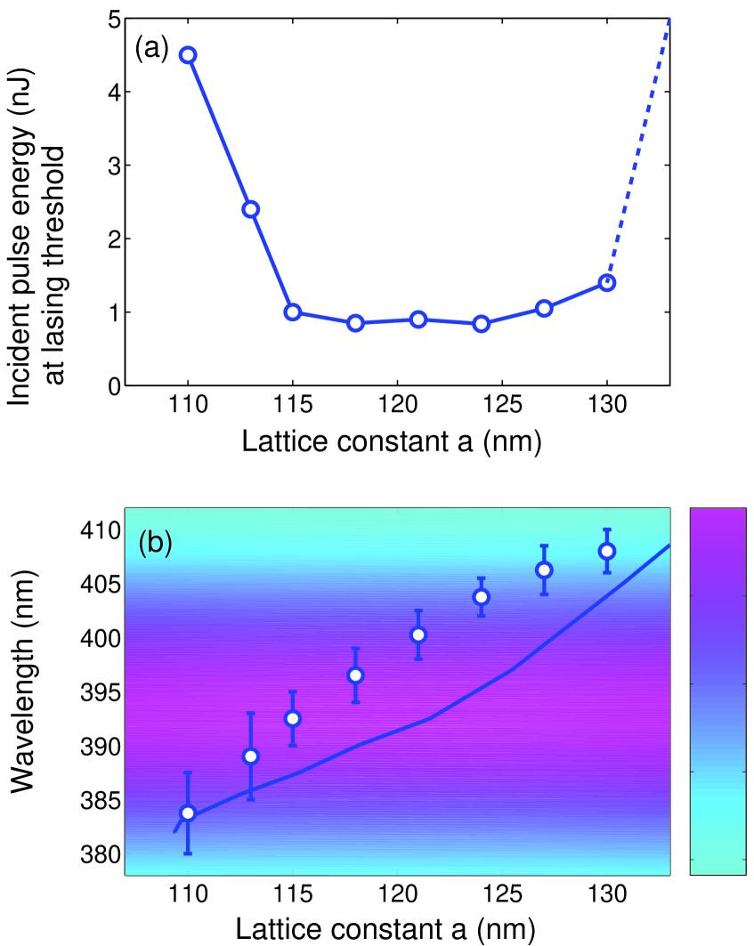
ZnO PhCS was optically pumped by the third harmonics of a pulsed Nd:YAG laser ( = 355 nm, 10 Hz repetition rate, 20 ps pulse width) at room temperature our_apl . In m patterns without intentionally-introduced structural defect, the ensemble-averaged lasing threshold exhibited a pronounced minimum at nm and [Fig. 4(a)]. To understand this phenomenon, we calculated the photonic bands in ZnO PhCS using the computational technique described in Ref.our_pbg_calc . The frequency dependence of ZnO refractive index was taken into account. In Fig. 4 (b), the wavelength of the dielectric bandedge for the fundamental PBG of TE modes our_apl is plotted against the lattice constant . The structural parameters were extracted from the SEM of our samples. The ZnO slab thickness nm, and . By comparing the lasing wavelength to in Fig. 4(b), we confirmed that the lasing modes were located in the vicinity of the dielectric bandedge. This can be explained by two factors: (i) the electric field of the modes near the dielectric bandedge is concentrated inside ZnO, and thus experience more gain [Fig. 3(c)]; (ii) the vanishing group velocity at the bandedge enhances light amplification gain_at_be . The dip in the measured lasing threshold [Fig. 4(a)] is attributed to spectral overlap of the dielectric bandedge with ZnO gain spectrum. In Fig. 3(b), the measured lasing threshold decreases monotonously with the pattern size for = 115 nm and 118 nm. These data agree qualitatively with the numerical simulation results shown in Fig. 3(a). In all patterns with intentionally missed air holes, the lasing modes were not pinned at the location of the missing hole due to the existence of better confined modes away from the defect. This observation is in line with our numerical simulation of large patterns with single artificial defect.
In summary, the structural disorder may lead to self-optimization of optical confinement in a PhCS and formation of high- modes which serve as the lasing modes. In a sufficiently large PhCS with short-range disorder, a microcavity with balanced and can be formed spontaneously without any carefully-designed structural defects. Despite the disorder, photonic bandedge effect enables us to efficiently extract optical gain and to fine-tune the lasing wavelength from nm to nm with sample-to-sample fluctuation of about nm in ZnO PhCS lasers.
This work was supported by the National Science Foundation under the grant no. ECS-0244457.
References
- (1) P. R. Villeneuve et al, IEE Proc.-Optoelectron. 145, 384 (1998); O. Painter, J. Vukovi and A. Scherer, J. Opt. Soc. Am. B 16, 275 (1999); E. Miyai and K. Sakoda, Opt. Lett. 26 740 (2001).
- (2) O. Painter et al, Science 284, 1819 (1999); S. Noda, A. Chutinan and M. Imada, Nature 407, 608 (2000). G. H. Park et al, Science 305, 1444 (2004);
- (3) M. Lonar et al, Appl. Phys. Lett. 81, 2680 (2002).
- (4) Y. Akahane et al, Nature 425, 944 (2003).
- (5) B.-S. Song et al, Nature Materials 4, 207 (2005).
- (6) M. Imada et al, Appl. Phys. Lett. 75, 316 (1999). H.-Y. Ryu et al, Appl. Phys. Lett.80, 3476 (2002);
- (7) S. Noda et al, Science 293, 1123 (2001).
- (8) X. Wu et al, Appl. Phys. Lett. 85, 3657 (2004).
- (9) A. Yamilov, X. Wu and H. Cao, J. Appl. Phys. 98, 103102 (2005).
- (10) P. L. Gourley et al, Appl. Phys. Lett. 64, 687 (1993); R. D. Meade et al, J. Appl. Phys. 75, 4753 (1994); T. F. Krauss, R. M. De La Rue and S. Brand, Nature 383, 699 (1996); S. G. Johnson et al, Phys. Rev. B 60, 5751 (1999); E. Chow et al, Nature 407, 983 (2000).
- (11) M. Meier et al, Appl. Phys. Lett. 74, 7 (1999); M. Notomi, H. Suzuki and T. Tamamura, Appl. Phys. Lett. 78, 1325 (2001).
- (12) S. Nojima, Jpn. J. Appl. Phys. (Part 2) 37, L565 (1998); K. Sakoda, K. Ohtaka and T. Ueta, Opt. Exp. 4, 481 (1999). L. Florescu, K. Busch and S. John, J. Opt. Soc. Am. B 19, 2215 (2002);
- (13) V. M. Apalkov and M. E. Raikh, Phys. Rev. Lett. 90, 253901 (2003).
- (14) X. Liu, W. H. Wu, H. Cao, and R. P. H. Chang, J. Appl. Phys. 95, 3141 (2004).
- (15) A. F. Koenderink, A. Lagendijk and W. L. Vos, Phys. Rev. B 72, 153102 (2005).
- (16) See e.g. M. Skorobogatiy, G. Begin and A. Talneau, Optics Express 13, 2488 (2005); J. M. Rico-Garcia, J. M. Lopez-Alonso and J. Alda, Optics Express 13, 3802 (2005); D. Gerace, L. C. Andreani, Optics Express 13 4939 (2005) and references therein.
- (17) S. Hughes et al, Phys. Rev. Lett. 94, 033903 (2005).
- (18) A. Yamilov and H. Cao, Phys. Rev. A 69, 031803 (2004).