Duisburg-Essen University
D-47048 Duisburg, Germany
The Dow Chemical Company
Solids Processing Laboratory
Freeport TX 77541, USA
PACS number(s): 45.70.-n, 62.20.-x, 83.10.Rs
Influence of particle elasticity in shear testers
Abstract
Two dimensional simulations of non-cohesive granular matter in a biaxial shear tester are discussed. The effect of particle elasticity on the mechanical behavior is investigated using two complementary distinct element methods (DEM): Soft particle molecular dynamics simulations (Particle Flow Code, PFC) for elastic particles and contact dynamics simulations (CD) for the limit of perfectly rigid particles. As soon as the system dilates to form shear bands, it relaxes the elastic strains so that one finds the same stresses for rigid respectively elastic particles in steady state flow. The principal stresses in steady state flow are determined. They are proportional to each other, giving rise to an effective macroscopic friction coefficient which is about 10 % smaller than the microscopic friction coefficient between the grains.
Keywords:
Granular matter, Contact Dynamics Simulations, Molecular Dynamics Simulation, Distinct Element Method, biaxial test, shearing, shear tester, steady state flow, elasticity1 Introduction
In powder technology the material flow properties are usually determined experimentally, e.g. using shear testers schwedes2003 . The measurements provide input for various phenomenological continuum models that have been proposed in order to calculate dense granular flows. These models contain parameters whose connection to the properties of the grains is not yet understood. It is the aim of distinct element simulation methods (DEM) to establish the connection between the grain scale and the macroscopic behavior directly cundall71 ; cundall79 .
The stress-strain behavior of a dense granular assembly consists of two parts: the rearrangement of the particles on the one hand, and their individual elastic or plastic deformation on the other. In this paper we address the question, how strongly the flow properties are influenced by the grain deformations compared to particle rearrangements. Therefore, two different distinct element methods are used: soft particle molecular dynamics modelling elastic particles (used here: PFC) and contact dynamics (CD) to simulate perfectly rigid particles. By comparing the results of the two methods the influence of particle elasticity can be separated from the effect that particle rearrangements have on the macroscopic stress-strain behavior found in e.g. the biaxial shear tester considered here.
We simulate dense granular flow in a biaxial tester, which allows for larger displacements than the Jenike shear cell. The biaxial shear tester is a rectangular box nowak94 ; janssenCET in which the material is sheared under constant strain rate in one direction and constant stress in a perpendicular direction while the load plates in the third direction are fixed. In this setup one will reach steady state flow (constant volume and stress tensor), and the yield locus can be determined.
2 Models
Both models we use simulate the trajectory of each individual particle by integrating Newton’s equations. They mainly differ in the way, how the contact forces between grains are determined. In soft particle molecular dynamics (PFC) microscopic elastic deformations of each particle have to be taken into account: They determine the forces. By contrast, in contact dynamics (CD) particles are considered as perfectly rigid, and forces are calculated from the volume exclusion constraint.
In order to make the comparison between the two methods as stringent as possible, we simulate a very simple two dimensional system of noncohesive round particles (disks) with Coulomb friction. The boundary conditions and initial particle configurations are the same for both types of simulations. In both cases the normal restitution coefficient is zero and the friction coefficient is . In order to give specific numbers we also introduce dimensional parameters, which have no effect on the simulations: The average particle radius is 1 mm, the mass density of the material the particles are made of is kg/m3. Whereas no further parameters enter CD, the molecular dynamics algorithm requires the specification of two stiffness parameters as the particles are not perfectly rigid.
2.1 Molecular Dynamics Simulation
The Particle Flow Code used here is based on soft particle molecular dynamics cundall79 ; cundall82 . Deformations of colliding particles are represented by the overlap of idealized disks, i.e. interaction forces between the particles are functions of the overlap (= sum of the two disk radii - distance between the disk centers).
The force between particles during contact is calculated with mechanical elements such as springs and dashpots wolf96 ; luding2004 . In Fig. 1 a basic visco-elastic contact model for two particles in contact is depicted schematically. The contact force is decomposed into a normal and a tangential component. In the simplest case used here the normal force is assumed to depend linearly on the overlap (the displacement of the spring). The dashpot contributes a normal dissipative force proportional to the time derivative of the overlap. The sum of both contributions is restricted to be repulsive, i.e. tensile normal forces are not allowed, because the particles are assumed to be non-cohesive.
The tangential component of the contact force is implemented in terms of a linear spring-dashpot as well, where the displacement of the spring is the integral of the tangential relative velocity over the time of nonzero overlap. This represents static friction, hence it is restricted to absolute values smaller than . When this threshold is reached, the tangential relative motion is regarded as sliding with sliding friction (directed opposite to the tangential relative velocity).
The boundary conditions of the system are realized by either strain driven walls or stress driven walls without any friction. For all of the PFC simulations the commercial Particle Flow Code (PFC2d ver3.0 PFC2dmanual ) was used.


For the PFC simulations, disks and walls with normal and tangential stiffness coefficients of 1 N/m are used. This low stiffness has been chosen in order to emphasize the possible difference compared to the perfectly rigid particles in CD (stiffness ). Moreover this keeps the computing time for PFC low (it increases with the square root of the stiffness). The viscous damping coefficient is set equal to the critical damping factor at each contact so that the restitution coefficients are zero for all particle contacts.
2.2 Contact Dynamics
The contact dynamics simulation method has been used for the simulation of dense and dry granular materials since the beginning of the 1980’s. Presuming that the behavior of these materials is governed by perfect volume exclusion and static Coulomb friction loetstedt82 ; jean92 ; jean99 ; moreau94 ; unger2002b ; brendel2004 , CD implements them as constraints without modelling the microscopic elastic grain deformations underlying them. Although CD can deal with more general systems as well kadau2003 we restrict ourselves to the simplest case here.

Volume exclusion of perfectly rigid particles is characterized by the Signorini graph, Fig. 2(left): When two particles touch each other () the normal force at the contact assumes whatever positive value is needed to avoid interpenetration. This value can in principle be arbitrarily large (Fig. 2, left). Otherwise the particles do not interact. The tangential force at a contact is determined by the Coulomb friction law, Fig. 2 (right): A sticking contact (with relative tangential velocity ) can bear any tangential force with absolute value up to a threshold . Exceeding this threshold leads to sliding of the two particles in contact. If sliding occurs () the magnitude of the tangential force is , while its direction is opposite to the sliding velocity.
For dense systems consisting of many particles with a complex contact network, the calculation of all contact forces is a global problem, because every force at a contact influences all other contact forces. There exists no analytical solution for this complex problem radjai96 ; unger2004 , so that an iterative procedure is applied: The forces at every contact are calculated in a random order repeatedly until they all comply with each other. In the simulations presented here a fixed number of iterations is chosen, which according to our previous experience unger2002 is large enough that the forces have converged within a small tolerance. If the number of iterations would be too small, quasielastic effects would occur unger2002 .
3 Simulated System
We simulate a rectangular system confined by frictionless walls perpendicular to the x- and y-axes, Fig. 3. The boundary conditions are such that the material is sheared under constant stress at the yielding walls (perpendicular to the x-axis) and with a constant strain rate at the pushing walls (perpendicular to the y-axis). The stress at the pushing walls, , and the strain rate at the yielding walls, , are evaluated. Since there is no wall friction in our simulations, and are the principal stresses.
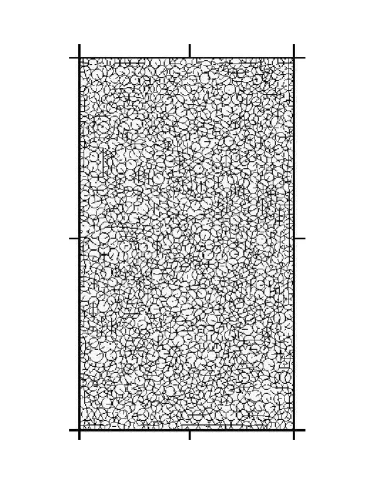
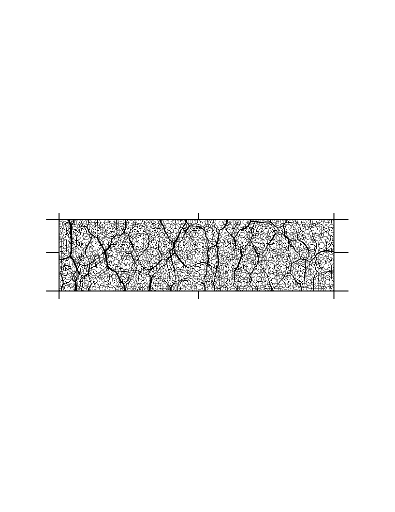
In the PFC and CD simulations the same initial configurations are used. The system consists of about 800 round particles (disks) with a Gaussian distribution of diameters cut off below and above of the average value. The width of the distribution is times the average particle diameter. The polydispersity is important to avoid layering within the system.
The initial configuration is prepared in the following way: The particles are randomly distributed at low concentration at first. Using contact dynamics the system is then biaxially compacted under small constant forces on the four walls (leading to stresses small compared to the ones applied later). This leads to a dense packing (Fig. 3, left). The forces in -direction were twice as large as those in -direction in order to obtain an aspect ratio of about 2:1. If the average particle radius is taken as 1 mm, the system size is about 43mm (-direction) times 73mm (-direction). Whereas in CD this configurations can be directly used as initial configuration (), a further preprocessing step is needed for PFC. Using molecular dynamics the configuration is compressed a little in x-direction until the desired stress is reached due to elastic response of the grains (here: small overlaps), while the extent in y-direction is kept constant. Therefore the initial volume of the PFC-simulation (Fig. 3, right) is about 6% smaller in the x-direction than the one of the CD-simulation, but otherwise the initial configurations are the same.

To reduce fluctuations the results were averaged over 10 similar systems where particles are randomly dispersed and located while keeping the same average distribution.
4 Results
These dense systems (Fig. 3) are sheared under a constant strain rate s-1 and different values of constant stress . The stresses are calculated by dividing the force on the corresponding wall by the wall area, where the average disk radius, 1 mm, is taken as size perpendicular to the xy-plane.
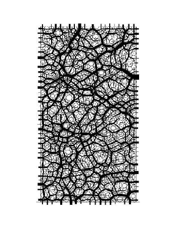
For Pa an example of a system after shearing for s is shown in Fig. 4. As will be discussed below, at this time steady state flow has already been established. The vertical size of the simulation boxes is the same, because the strain rate is the same in both simulations. Remarkably, the horizontal size difference is still about 6%, as for the initial configurations, although it could have evolved differently depending on the elastic properties, and in fact transiently does so. The strain built up temporarily due to elasticity vanishes again in steady state flow. The final particle positions are different in the two simulation methods, although they were initially the same, which is no surprise in view of the highly nonlinear dynamics. In particular the force network evolves differently. On the other hand, Fig. 5 compares the distributions of normal forces for a snapshot like Fig. 4. The distributions obtained with CD and PFC are similar, thus the force statistics in the systems are comparable.
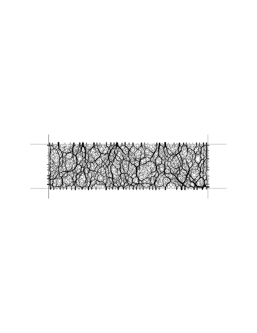

We evaluated the velocities of the grains for the CD-simulations and found shear localization in shear bands. In contrast to previous simulations luding2004b ; luding2005 ; luding2005b , where the left wall was fixed, i.e. strain controlled, whereas the right one was stress controlled, the shear band which forms initially, is oriented along either diagonal, breaking the symmetry of our system spontaneously. Later on most of the time four shearbands exist which form roughly a parallelogram around the center which hardly moves. The dynamics of the shear bands is very complex showing eddies and strong fluctuations. This will be analyzed in more detail in a forthcoming publication torok2005 .
The measured strain rate , averaged over 10 similar systems is shown in Fig. 6. One can distinguish three time intervals: During the first 2.5 s the elastic particles are compressed, i.e. . As expected, this region is much smaller for CD, where the system of rigid disks gets compacted for only about 1 s, mostly due to numerical errors creating tiny overlaps, which for perfect convergence of the force iterations would not occur. However, a small amount of compaction due to particle rearrangements is also possible. The second time interval extends up to 10 s in both simulation models and is characterized by , which means that the system dilates. The volume increases to allow for shearing reynolds1885 . As already seen in Fig. 4 the elastic system dilates more, compensating for the initial compression, so that finally the volumes of both systems differ by roughly the same percentage as initially. Obviously the elastic energy stored during the compression phase is completely released during dilation. After this transient the system reaches a steady state where the strain rate fluctuates around the average value . In this region the average volume remains constant. The PFC-results agree qualitatively with the ones obtained with molecular dynamics simulations by Luding luding2004b ; luding2005 ; luding2005b .


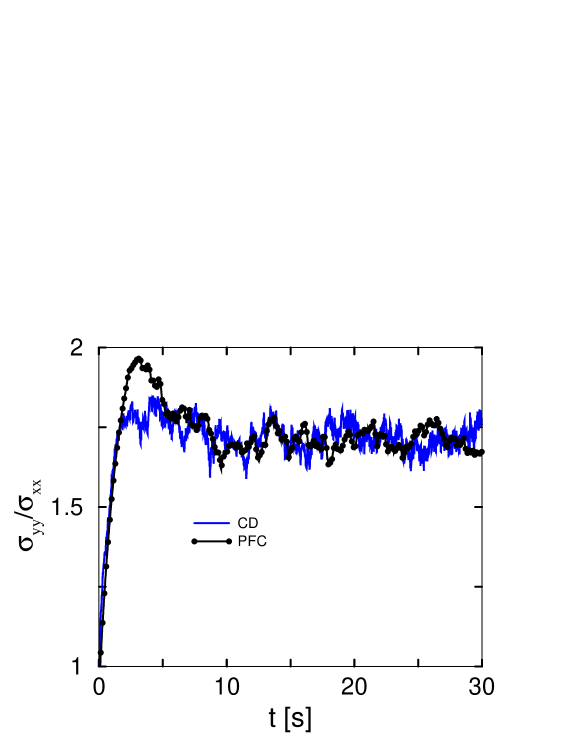
The time dependence of the stress is shown in Fig. 7: For elastic particles (PFC) it reaches a pronounced maximum at the end of the compression phase after about 3 s. During the dilatancy phase it decreases and finally fluctuates around a constant value in steady state flow. For rigid particles (CD) the stress maximum is not very pronounced: In order to distinguish it convincingly from the fluctuations, one would have to average over more than 10 independent runs. This confirms that the stress maximum is due to elastic compression of the system. On the other hand, the average steady state values of are the same for PFC and CD within the error bars. Elastic contributions to cannot be observed any more in agreement with our picture, that the elastic deformation relaxes during dilation at the onset of shearing.
We repeated the simulations for four different stresses between 5 and 25 Pa keeping the strain rate the same. The time-dependence of the strain rate as well as of the stress ratio is in all cases the same as in Fig. 6 respectively Fig. 7. In particular, time-averaged in steady state flow does not depend on , see Fig. 8. 111Although the average values for CD seem to be slightly larger than those for PFC by 1 to 3 %, the error bars are so big that the above statement that elasticity does not play a significant role in steady state flow is still valid.

As both principal values of the stress tensor are proportional to each other in steady state flow, this implies a linear effective yield locus. The effective friction angle is given by
| (1) |
With this implies an effective friction coefficient
| (2) |
which is slightly smaller than the friction coefficient between the grains, .
The effect of system size was investigated by increasing the number of particles to 10000. However, no effect of the system size on the stress ratio was found.
5 Conclusion
The results presented above for a two dimensional model of a biaxial shear test show that particle elasticity only affects the stress and volumetric strain during a short transient. Dilatancy leads to elastic strain relaxation so that the stress in steady state flow is essentially determined by rearrangements of the particles. This could be proven by comparing the simulation results obtained for elastic and perfectly rigid particles, respectively.
In steady state flow the principal stresses turned out to be proportional to each other. Using Mohr-Coulomb theory we determined the effective macroscopic friction coefficient of the granular material, which is the ratio of the shear stress to the normal stress at a shear plane. We could relate it to the microscopic friction coefficient between the grains, which is slightly larger.
We also checked the influence of the strain rate and found essentially no effect. This can be explained by comparing the orders of magnitude of inertia forces due to the prescribed strain rate to the forces in the system caused by the applied stress . The typical time scale for inertia effects is given by the inverse strain rate , the length scale is given by the system size , the typical mass is the average particle mass (we neglect the factor here). Thus, typical inertia forces are: . Typical forces due to the applied stress are estimated by multiplying with the system size (and its thickness ): . The interesting ratio: . Inserting the used values results in: which is a small number so that we are well in the region of slow (quasistatic) deformations where we do not expect an influence of the applied strain rate on the results as is found here. This argument shows, that only the dimensionless ratio matters, as long as elastic effects are negligible: Increasing is equivalent to decreasing .
References
- [1] J. Schwedes. Review on testers for measuring of properties of bulk solids. Granular Matter, 5:1–43, 2003.
- [2] P.A. Cundall. A computer model for simulating progressive large scale movements of block rock systems. In Proceedings of the Symposium of the International Society of Rock Mechanics, volume 1, pages 132–150, Nancy, France, 1971.
- [3] P.A. Cundall and O.D.L Strack. A discrete model for granular assemblies. Geotechnique, 29:47–65, 1979.
- [4] M. Nowak. Spannungs-/Dehnungsverhalten von Kalkstein in der Zweiaxialbox. PhD thesis, TU Braunschweig, 1994.
- [5] R. J. M. Janssen and H. Zetzener. Measurements on cohesive powder with two biaxial shear testers. Chemical Engineering & Technology, 26(2):147–151, ??
- [6] P.A. Cundall. Distinct element models of rock and soil structure. In Analytical and computational methods in engineering and rock mechanics, London, England, 1987. Allen & Unwin.
- [7] D.E. Wolf. Modelling and computer simulation of granular media. In K.H. Hoffmann and M. Schreiber, editors, Computational Physics: Selected Methods - Simple Exercises - Serious Applications, pages 64–94, Heidelberg, 1996. Springer.
- [8] S. Luding. Molecular dynamics simulations of granular materials. In H. Hinrichsen and D. E. Wolf, editors, The Physics of Granular Media, Berlin, Germany, 2004. Wiley-VCH.
- [9] Itasca consulting, www.itasca.com. Particle Flow Code in 2 Dimensions. Online manual PFC2d version 3.0.
- [10] P. Lötstedt. Mechanical systems of rigid bodies subject to unilateral constraints. SIAM J. Appl. Math., 42:281–296, 1982.
- [11] M. Jean and J. J. Moreau. Unilaterality and dry friction in the dynamics of rigid body collections. In Proceedings of Contact Mechanics International Symposium, pages 31–48, Lausanne, Switzerland, 1992. Presses Polytechniques et Universitaires Romandes.
- [12] M. Jean. The non-smooth contact dynamics method. Comput. Methods Appl. Engrg., 177:235–257, 1999.
- [13] J.J. Moreau. Some numerical methods in multibody dynamics: application to granular materials. Eur J Mech, A/Solids, 13(4):93–114, 1994.
- [14] T. Unger and J. Kertész. The contact dynamics method for granular media. In Modeling of Complex Systems, pages 116–138, Melville, New York, 2003. American Institute of Physics. cond-mat/0211696.
- [15] L. Brendel, T. Unger, and D. E. Wolf. Contact dynamics for beginners. In H. Hinrichsen and D. E. Wolf, editors, The Physics of Granular Media, Berlin, Germany, 2004. Wiley-VCH.
- [16] D. Kadau, G. Bartels, L. Brendel, and D. E. Wolf. Pore stabilization in cohesive granular systems. Phase Trans., 76(4-5):315–331, 2003.
- [17] F. Radjai, L. Brendel, and S. Roux. Nonsmoothness, indeterminacy, and friction in two dimensional arrays of rigid particles. Phys. Rev. E, 54(1):861, 1996.
- [18] T. Unger, J. Kertész, and D. E. Wolf. Force indeterminacy in the jammed state of hard disks. Phys. Rev. Lett., 94:178001, 2005.
- [19] T. Unger, L. Brendel, D. E. Wolf, and J. Kertész. Elastic behavior in contact dynamics of rigid particles. Phys. Rev. E, 65(6):061305, 2002.
- [20] S. Luding, R. Tykhoniuk, J. Tomas, L. Heim, M. Kappl, and H.-J. Butt. Flow behavior of cohesive and frictional fine powders. In Y. Shimizu, R. D. Hart, and P. A. Cundall, editors, Numerical Modeling in Micromechanics via Particle Methods - 2004, pages 157–163. A. A. Balkema, 2004. PFC Symposium procedings.
- [21] S. Luding. Anisotropy in cohesive, frictional granular media. J. Phys.: Condens. Matter, 17:S2623–S2640, 2005.
- [22] S. Luding. Shear flow modeling of cohesive and frictional fine powder. Powder Technology, 2005. In press, corrected proof available online 23 May 2005.
- [23] J. Török, D. Kadau, and D. E. Wolf. Properties of shear bands in biaxial tests. in preparation.
- [24] O. Reynolds. On the dilatancy of media composed of rigid particles in contact. Philos. Mag., Ser. 5(20):469, 1885.