Photoinjector-generation of a flat electron beam
with
transverse emittance ratio of
Abstract
The generation of a flat electron beam directly from a photoinjector is an attractive alternative to the electron damping ring as envisioned for linear colliders. It also has potential applications to light sources such as the generation of ultra-short x-ray pulses or Smith-Purcell free electron lasers. In this Letter, we report on the experimental generation of a flat-beam with a measured transverse emittance ratio of for a bunch charge of nC; the smaller measured normalized root-mean-square emittance is m and is limited by the resolution of our experimental setup. The experimental data, obtained at the Fermilab/NICADD Photoinjector Laboratory, are compared with numerical simulations and the expected scaling laws.
pacs:
29.27.-a, 41.85.-p, 41.75.FrFlat electron beams, e.g. beams with large transverse emittance ratios, have been proposed in the context of linear colliders and some novel electron-beam-based light sources. In the case of a linear e+/e- collider, a flat beam at the interaction point reduces the luminosity disruption caused by beamsstrahlung yokoya . In the case of light sources, such as the LUX project proposed at LBL lux , a flat beam with a smaller emittance of 0.3 m and emittance ratio of 50 is needed to produce x-ray pulses that can be compressed to the order of femtoseconds via standard x-ray pulse compression techniques zholents . Another type of light source recently drawing attention is based on self-amplification of Smith-Purcell radiation smithpurcell . Given one or two planar metal gratings, a flat beam could enhance the interaction between the electrons and metal grating surface, thus reducing the gain length associated with the Smith-Purcell free-electron-laser mechanism kjk2 ; sp ; YHzhang .
In the proposed International Linear Collider (ILC) the needed flat-beam parameters (emittance ratio of 300) are foreseen to be achieved via radiation cooling in a damping ring ilc . Although the required transverse emittances for the ILC have been demonstrated at the ATF damping ring of KEK kek , ILC puts stringent requirements on the damping ring design, and the cost of the damping ring is a significant portion of the total collider cost. Therefore alternative ways of producing flat beams directly from an electron source have been explored by several groups rosenzweig . In conjunction with the invention of a linear transformation capable of transforming an incoming flat beam into an angular-momentum-dominated (or “magnetized”) beam derbenev , a scheme which inverses this transformation was proposed to generate a flat beam directly out of a photoinjector brinkmann2 . The method consists of generating an magnetized beam by immersing the photocathode in an axial magnetic field. After acceleration, the beam is transformed into a flat beam using three skew quadrupoles BurovDanilov . This has been verified experimentally Edwards ; Edwardspac01 ; flat2 ; yineprstab , and transverse emittance ratios of 40-50 were reported. Theoretical analysis of the conversion of a magnetized cylindrically-symmetric beam into a flat beam has been presented BND-PRE ; kjk and some of the associated limitations explored yinesunlinac2004 ; yinesunpac2005 . In the present Letter we report on an improvement of the experimental conditions and methods that led to a measured transverse emittance ratio of approximately 100.
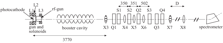
The flat-beam experiment was carried out at the Fermilab/NICADD 111NICADD is an acronym for Northern Illinois Center for Accelerator and Detector Development. Photoinjector Laboratory (FNPL) fnpl ; see Fig. 1 for the layout. In brief, electron bunches with variable charge (20 nC) are generated via photoemission from a cesium telluride photocathode located at the back plate of a 1+1/2 cell radio-frequency (rf) cavity operating at 1.3 GHz (the “rf gun”). The beam is then accelerated in a 1.3 GHz superconducting rf cavity (the booster cavity) sccavity to approximately 16 MeV. The rf gun is surrounded by three solenoidal lenses that are designed to control the beam transverse emittance. For flat-beam production the first solenoidal lens (L1) is turned off, and the two others (L2 and L3) are tuned to provide the desired magnetic field on the photocathode along with the proper focusing. The beam is thereby produced in the presence of a significant axial magnetic field and has an average angular momentum given by , where is the electron charge, the axial magnetic field on the photocathode surface, and the root-mean-square (rms) transverse size of the drive-laser spot on the photocathode. The transformation of the magnetized beam into a flat beam occurs downstream of the booster cavity. Three skew quadrupoles (S1, S2, and S3 in Fig. 1) provide a net torque on the beam thereby removing its initial angular momentum KJKtorque ; yinephD . The skew quadrupoles are henceforth referred to as the “transformer”. Given the incoming beam covariance matrix , the quadrupole strengths are set to provide the proper transport matrix so that the covariance matrix at the exit of the transformer, (where the upper tilde denote the transpose), is block-diagonal. An analytical solution for the quadrupole settings was derived under the thin-lens approximation for the quadrupoles flat2 . This solution is used as a starting point for a simplex minimization algorithm that searches the quadrupole settings to minimize the figure-of-merit , where is the element of matrix . Upon proper tuning of the transformer, the expected normalized flat-beam emittances, , are given by BND-PRE ; kjk
| (1) |
where is the normalized uncorrelated emittance of the magnetized beam prior to the transformer, , is the Lorentz factor, , and is the longitudinal momentum. Note that .
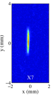
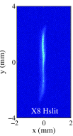
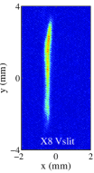
The flat-beam emittances are measured using the slit method lejeune . A movable single-slit assembly (either vertical or horizontal), located at position X7 (see Fig. 1), is used to sample the beam in one direction. The slit assembly consists of a m slit made of a 3 mm thick tungsten block. The beamlet passing through the slit is observed after a drift of distance , at the location X8. Given the measured horizontal beam size at X7, , and horizontal rms size of the beamlet at X8 when a vertical slit is inserted at X7, , the horizontal emittance is then computed as the product . Similarly the vertical emittance is measured as where is the vertical rms size of the beamlet at X8 when a horizontal slit is inserted at X7. The beam viewer at locations X7 is an optical transition radiation (OTR) foil, while at X8 it is a yttrium aluminum garnet (YAG) screen. The measured rms beam size, , is affected by the resolution of the diagnostics and spurious dispersion introduced, e.g., by steering dipoles required to keep the beam centered along the beamline axis: , where is the rms fractional momentum spread of the beam. The measurement method used to report emittances in the following was numerically benchmarked yinephD . The resolution of the beam size measurement system which includes the optical components and a charged coupled device (CCD) camera was characterized for various operating points yinephD . For all the quoted measurements of transverse beam sizes, we quadratically subtract the smallest measured resolution ( m). The unavoidable contribution from spurious dispersion (discussed later) results in an overestimated value for the smaller flat-beam emittance. Hence the emittance ratio reported hereafter is underestimated.
For the flat-beam experiment reported in this Letter, the nominal operating parameters for the photoinjector are reported in Table 1. The rf-gun and booster-cavity settings are kept the same during the experiment while the drive-laser spot size on the photocathode and the solenoid currents are adjusted for the different sets of measurements.
| parameter | value | unit |
|---|---|---|
| laser injection phase | 25 | degree |
| rms laser spot size on cathode | 0.75 1 | mm |
| rms laser pulse duration (Gaussian) | 3 | ps |
| bunch charge | 0.5 | nC |
| accelerating gradient on cathode | 32 | MV/m |
| axial magnetic field on cathode | 400 900 | Gauss |
| booster cavity peak electric field | 23 | MV/m |
Given the experimental conditions, numerical simulations are performed with the tracking program Astra astra . Using the simulation outputs of the beam properties at the entrance of the transformer, the aforementioned simplex minimization algorithm is used to determine the skew quadrupole settings needed to transform the magnetized round beam into a flat beam. In the experiment, the quadrupole settings are then empirically fine-tuned to insure the - correlation on the beam has been removed downstream of the transformer. This is achieved by observing the beam transverse image on the viewers downstream of the transformer: upon removal of the angular momentum, the beam should remain flat and upright. In Table 2 we compare, for two cases of rms drive-laser spot sizes (=0.76 mm and 0.97 mm), the final quadrupole currents used in the experiment with the initial values obtained numerically. Most of the quadrupole currents agree with predicted values, the larger discrepancies observed for the settings of the last quadrupole reflect a looser tolerance on this quadrupole setting yinesunpac2005 .
| quadrupole | mm | mm | ||
|---|---|---|---|---|
| current | experiment | simulation | experiment | simulation |
| I1(A) | -1.92 | -2.03 | -1.97 | -1.98 |
| I2(A) | 2.40 | 2.57 | 2.56 | 2.58 |
| I3(A) | -2.99 | -4.01 | -4.55 | -5.08 |
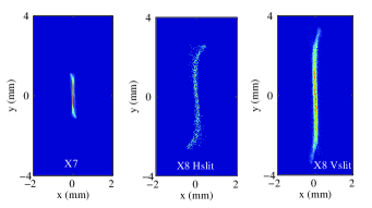
For the transverse emittance measurements, the beam images on the different viewers are taken for a single-bunch beam. In Figure 2, we present the set of experimental images, along with their respective simulated images, needed to infer the two transverse flat-beam emittances. Several shots of each of the particular images are taken and analyzed to obtain the rms beam sizes. The results are then averaged and a statistical error is attributed to the mean. Given the uncertainty of the measurement method the systematic errors are estimated from error propagation. The rms beam sizes are estimated on 95% of the total integrated image intensity. In Table 3, we gather the measured and simulated parameters for the case of mm.
| parameter | experiment | simulation | unit |
|---|---|---|---|
| 0.0880.01 (0.01) | 0.058 | mm | |
| 0.630.01 (0.01) | 0.77 | mm | |
| 0.120.01 (0.01) | 0.11 | mm | |
| 1.680.09 (0.01) | 1.50 | mm | |
| 0.410.06 (0.02) | 0.27 | m | |
| 41.12.5 (0.54) | 53 | m | |
| 100.220.2 (5.2) | 196 |
The smaller of the flat beam emittance is m; this is less than half of the expected thermal emittance due to the photoemission process of the cesium telluride material. From pitz ; themit , we infer the thermal emittance to be m given mm.
| parameters | round-beam | flat-beam | simulation |
|---|---|---|---|
| 25.62.6 | 26.3 | ||
| 5.10.9 | 3.8 | ||
| 53.85.4222expected value given the measured round beam parameters. | 41.02.5 | 53 | |
| 0.490.22a | 0.410.06 | 0.27 | |
| 5.10.9 | 4.10.8 | 3.8 |
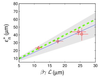
To gain more insight into the round-to-flat-beam transformation, we compare the expected flat-beam emittances, in Eq. (1), given the incoming magnetized beam parameters, with the measured flat-beam emittances downstream of the transformer. The uncorrelated emittance of the magnetized beam is measured using the slit technique from the beam image at X3 and the corresponding slit images at X5. has been obtained with the two different methods detailed in yineprstab . The resulting measurements for the case mm are summarized in Table 4: within the experimental errors we observed that the measured four-dimensional (4-D) emittance is conserved during the round-to-flat-beam transformation. We note a 25% discrepancy for the measured larger flat-beam emittance, compared to the simulation and the value predicted from the round beam parameters. This is probably due to imperfectly optimized settings for the transformer. We finally report the dependence of versus . The value of was varied either by changing or . As expected is linearly dependent on , and a linear regression gives ; see Fig. 3. The slope is in agreement with the theoretically expected slope value of 2 in the limit ; see Eq. (1).
In summary we generated and characterized a highly asymmetric beam in a photoinjector. The lower limit for the best measured emittance ratio of 100 is limited by our experimental set-up: the fact that the transformation occurs at low energy along with % made our measurement sensitive to spurious dispersion. Simulations based on steering dipole settings used to correct the beam orbit indicate that the thereby introduced dispersion could result in an overestimation of the smaller flat-beam emittance by a factor up to 2. Spurious dispersion accounts for most of the discrepancy between numerical simulations and measurements. The experiment is limited to low charge in order to avoid space charge to significantly impact the beam dynamics in the transformer at 16 MeV. Nonetheless our measurements support the potential flat-beam injector designs either for proposed light source such as LUX or envisioned Terahertz radiation sources based on Smith-Purcell effect. Our results also open a possible path for the production of flat e--beam for the ILC, where the main challenge is to also achieve a 4-D emittance m for nC. This value is one order of magnitude lower than what our photoinjector can presently produce at nC.
We wish to acknowledge C. L. Bohn, D. Edwards, and H. Edwards, for encouragements, fruitful discussions and comments. We are thankful to J. Li and R. Tikhoplav for improving the photocathode laser.
References
- (1) K. Yokoya and P. Chen, in Proceedings of the 1989 Particle Accelerator Conference, Chicago, IL, 1989, edited by F. Bennett and J. Kepta (IEEE, New York, NY, 1989), pp. 1438-1440.
- (2) W. Barry et. al, Lawrence Berkeley National Lab. Report No. LBNL-51766, 2002.
- (3) A. Zholents, P. Heimann, M. Zolotorev and J. Byrd, Nucl. Instrum. Methods A 425, 385-389 (1999).
- (4) S. J. Smith and E. M. Purcell, Phys. Rev. 92, 1069 (1953).
- (5) K.-J. Kim and S.-B. Song, Nucl. Instrum. Methods A 475 158-163 (2001); V. Kumar and K.-J. Kim submitted to Phys. Rev. E
- (6) H. L. Andrews and C. A. Brau, Phys. Rev. ST Accel. Beams 7, 070701 (2004).
- (7) Y. Zhang, Ya. Derbenev and R. Li, Nucl. Instrum. Methods A 507 459-463 (2003).
- (8) http://lcdev.kek.jp/ILCWS/.
- (9) Y. Honda, et al., Phys. Rev. Lett. 92, 054802 (2004).
- (10) J. B. Rosenzweig, E. Colby, G. Jackson and T. Nicol, in Proceedings of the 1993 Particle accelerator Conference, Washington DC, edited by S. T. Corneliussen (IEEE, Piscataway, NJ, 1993), pp. 3021-3023; G. Fiorentini, C. Pagani, and L. Serafini, in Proceedings of the 1995 Particle accelerator Conference, Dallas, TX, edited by L. T. Gennar and R. H. Siemann (IEEE, Piscataway, NJ, 1995), pp. 973-975.
- (11) Ya. Derbenev, University of Michigan Report No. UM-HE-98-04, 1998.
- (12) R. Brinkmann, Y. Derbenev and K. Flöttmann, DESY Report No. TESLA 99-09, 1999; Phys. Rev. ST Accel. Beams 4, 053501 (2001).
- (13) A. Burov, V. Danilov, FERMILAB-TM-2043 (1998).
- (14) D. Edwards et al., in Proceedings of the XX International Linac Conference, Monterey, CA, pp. 122-124 (2000).
- (15) D. Edwards et al., in Proceedings of the 2001 Particle Accelerator Conference, Chicago, IL (IEEE, Piscataway, NJ, 2001), pp. 73-75.
- (16) E. Thrane et al., in Proceedings of the XXI International Linac Conference, Gyeongju, Korea (Pohang Accelerator Laboratory, Pohang, Korea, 2002), pp. 308-310.
- (17) Y.-E Sun, et al., Phys. Rev. ST Accel. Beams 7, 123501 (2004).
- (18) A. Burov, S. Nagaitsev and Ya. Derbenev, Phys. Rev. E 66, 016503 (2002).
- (19) K.-J. Kim, Phys. Rev. ST Accel. Beams 6, 104002 (2003).
- (20) Y.-E Sun, K.-J. Kim, and P. Piot, in Proceedings of the XXII International Linac Conference, Lubeck, Germany, pp. 150-152 (2004)
- (21) Y.-E Sun, K.-J. Kim, and P. Piot, to appear in Proceedings of the 2005 Particle Accelerator Conference, Knoxville, TN; see also preprint fermilab-conf-05-158-AD (2005).
- (22) http://nicadd.niu.edu/fnpl.
- (23) B. Aune et al., Phys. Rev. ST Accel. Beams 3, 092001 (2000).
- (24) C. L. Bohn, private discussions.
- (25) Y.-E Sun, Ph.D. thesis, University of Chicago, 2005.
- (26) C. Lejeune and J. Aubert, Adv. Electron. Electron Phys. Suppl. A 13, 159 (1980).
- (27) K. Flöttmann, “Astra: A Space Charge Tracking Algorithm,” available at http://www.desy.de/mpyflo.
- (28) V. V. Miltchev, et al., in Proceedings of the 2004 FEL Conference, Trieste, Italy, pp. 399-402.
- (29) K. Flöttmann, DESY Report No. TESLA-FEL-1997-01, 1997.